Understanding how a pallet jack lifts starts with one idea: it turns small handle force into high hydraulic pressure to raise 2,000–2,500 kg loads efficiently. This guide breaks down the hydraulics, linkages, and design choices so you can diagnose faults, specify correctly, and operate safely.
We will connect Pascal’s Law, handle leverage, and the internal hydraulic circuit to the fork frame, wheels, and aisle constraints. By the end, you will know exactly what each component does, why it fails, and how to keep lifting performance consistent in real warehouses.
How A Pallet Jack Converts Handle Force Into Lift
How a pallet jack lifts is a two-stage conversion: the handle works as a lever, and the hydraulic circuit multiplies that force using fluid pressure to raise loads of up to around 2,000–2,500 kg. This section breaks that down into simple physics you can see on the shop floor.
In plain terms, your arms supply a small input force and stroke length at the handle. Lever geometry reduces the force but increases pressure at the pump plunger, and Pascal’s Law spreads that pressure across the larger piston area in the lifting cylinder, producing a much higher lifting force on the fork frame. Understanding this conversion helps you train operators, size equipment correctly, and diagnose “no lift” complaints efficiently.
Pascal’s Law And Force Multiplication
Pascal’s Law explains how a pallet jack multiplies a small handle force into a large lifting force: pressure applied to confined oil is transmitted equally in all directions and acts over the full piston area in the lift cylinder. The handle-driven pump creates hydraulic pressure in the oil, and that pressure acts on the larger ram to raise heavy pallets with modest operator effort. This is the core physics of how a pallet jack lifts.
The hydraulic system in a pallet jack operates on Pascal’s Law, where pressure applied to a confined fluid is transmitted equally in all directions. A small force at the pump piston creates hydraulic pressure that is then multiplied to lift heavy loads inside the lift cylinder. Each pump stroke moves a small volume of oil into a sealed chamber, with check valves preventing backflow so pressure can build progressively at the ram.
| Element | What It Does | Typical Behaviour / Range | Operational Impact |
|---|---|---|---|
| Operator handle force | Manual push/pull applied by hands | Low, comfortable effort by design | Allows most operators to lift 1,000–2,500 kg loads repeatedly without fatigue. |
| Handle pump piston | Creates hydraulic pressure in oil | Small piston area, high local pressure | Turns light handle effort into high oil pressure for lifting. |
| Hydraulic oil | Transmits pressure (Pascal’s Law) | Confined, nearly incompressible fluid | Ensures even pressure at all points in the circuit, giving smooth, even fork rise. |
| Check valves | Allow one-way oil flow | Open on pumping, close on return | Prevent pressure loss between strokes, so forks climb step by step rather than dropping back. |
| Lift cylinder (ram) | Converts pressure to lifting force | Larger piston area than pump piston | Multiplies pressure into enough force to raise pallet and truck weight. |
| Relief / safety valve | Limits maximum pressure | Opens above set pressure | Prevents overload damage when users try to lift beyond rated capacity. |
As pressurized oil enters the lifting cylinder, the piston moves upward and, through the mechanical linkage, raises the forks evenly from the ground to full stroke. Standard hand pallet jacks handle loads in the range of about 900–2,500 kg (2,000–5,500 lbs) when the hydraulic and mechanical components are in good condition and used within rated limits according to typical specs.
- Confined fluid principle: Oil in the pallet jack is trapped in a sealed chamber – this allows pressure to act uniformly and predictably on the lift piston.
- Force-to-pressure conversion: Handle strokes move a small piston – this turns mechanical force into hydraulic pressure without needing electric power.
- Pressure-to-force multiplication: The larger ram area sees the same pressure – this multiplies the lifting force so you can raise heavy pallets with light effort.
- Stepwise lifting: Check valves hold pressure between strokes – this gives controlled, incremental fork rise instead of jerky or reversing motion.
- Safety pressure limit: Relief valves vent excess pressure – this protects the pump and cylinder when someone overloads the pallet jack.
💡 Field Engineer’s Note: If a pallet jack “pumps” but the forks barely rise, think pressure losses: trapped air, worn seals, or a relief valve stuck slightly open will defeat Pascal’s Law long before the frame ever bends.
Handle Lever Geometry And Operator Effort
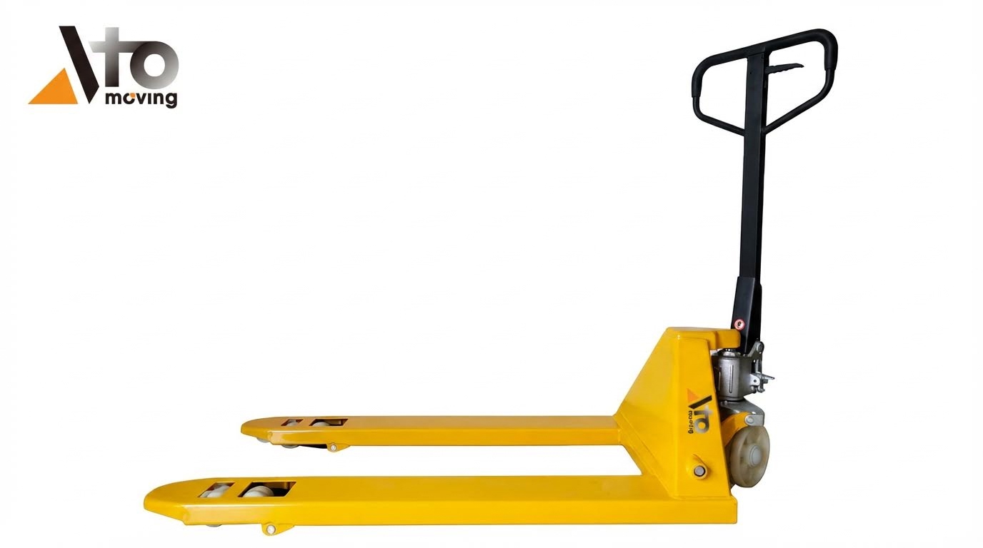
The handle of a pallet jack is a mechanical lever that reduces the force you must apply while increasing the stroke and pressure at the pump plunger, so the jack can lift heavy loads repeatedly without exhausting the operator. Its linkage also selects lift, neutral, or lower modes by engaging the pump or opening the lowering valve.
The handle performs steering, pumping, and valve actuation through a mechanical linkage that converts small angular movements into linear motion at the pump plunger and valve stems within the base unit. In the lift position, the linkage engages the pump while keeping the lowering valve closed; in neutral, both are isolated; in lower, the linkage opens the lowering valve so oil returns to the reservoir under gravity for controlled descent.
| Handle / Linkage Aspect | Engineering Role | Typical Behaviour | Operational Impact |
|---|---|---|---|
| Handle as lever | Multiplies operator input | Optimized lever ratio reduces torque demand on the user | Enables long shifts with minimal shoulder strain and better ergonomics. |
| Pump plunger stroke | Moves oil per handle pump | Small linear stroke for each handle sweep | More strokes per lift, but each stroke feels light and manageable. |
| Lift position | Engages pump, closes lowering valve | Forks rise incrementally with each stroke of the handle | Quickly gets the pallet clear of the floor with predictable effort. |
| Neutral (drive) position | Isolates pump and valve | Fork height stays fixed while moving the load | Prevents accidental lifting or lowering during travel, improving safety. |
| Lower position | Opens lowering valve | Oil returns to reservoir; forks descend smoothly under load | Allows precise placement of pallets without sudden drops or shocks. |
| Ergonomic optimization | Reduces required operating torque | Lever ratio and bearings tuned for low friction and smooth motion | Improves comfort and reduces repetitive-strain injury risk in high-cycle use. |
- Lever ratio design: The handle length and pivot points are chosen to cut required hand force – this keeps effort low even near the jack’s rated capacity.
- Multi-function linkage: One handle controls steering, pumping, and lowering – operators can maneuver and lift without changing grip or position.
- Stroke vs. speed trade-off: Longer handle travel per stroke moves more oil – designers balance lift speed against how far the operator must swing the handle.
- Valve timing sensitivity: Pins and joints must be correctly adjusted – misadjustment causes slow lift, constant creep-down, or failure to lower.
- Comfort and safety: Self-lubricating bearings and low-friction surfaces – reduce shock loads into the operator’s wrists and shoulders during daily use.
How handle position affects “no lift” complaints
If the control lever is slightly out of the lift detent, the linkage may partially open the lowering valve while you pump. The result is heavy effort with little or no fork movement. Always confirm handle position and linkage adjustment before assuming a hydraulic component failure.
💡 Field Engineer’s Note: When operators say “this jack is dead,” watch their hands first. A worn or misadjusted handle linkage that never fully reaches the lift position can mimic a bad pump, but it usually fixes with a 10 mm spanner and 5 minutes—not a new hydraulic unit.
Mechanical Linkages, Load Support, And Spec Selection
This section explains how a pallet jack lifts through its mechanical linkages, fork frame, chains, and wheel layout, and how these parts drive key specs like capacity, stability, and aisle width when you select or size a unit.
Understanding these components turns “how a pallet jack lifts” from theory into practical buying and maintenance decisions that reduce damage, strain injuries, and downtime.
Fork Frame, Linkage, And Chain Transmission
The fork frame, linkage, and (on stackers) chain transmission convert the hydraulic cylinder’s short stroke into the vertical lift and horizontal movement that actually raises and carries the pallet load.
When the hydraulic ram extends, it pushes a system of levers and connecting rods that rotate the load wheels down and the fork tips up. On manual pallet stackers, the same cylinder motion is routed through chains to lift a mast carriage, giving higher lift heights from a compact stroke. This composite hydraulic–mechanical arrangement is a core part of how a pallet jack lifts heavy loads with modest handle effort. Technical description of hydraulic and chain transmission
| Component | Main Function | Typical Design Notes | Operational Impact |
|---|---|---|---|
| Fork frame (forks + chassis) | Supports load and houses linkages | Steel weldment, fork length often 1,000–1,200 mm | Determines what pallet sizes you can pick up and how weight is distributed into wheels |
| Lift linkage (levers and rods) | Converts cylinder stroke into fork lift | Multiple pivot points with bushings or pins | Sets how many mm of fork rise you get per pump and how smooth the lift feels under load |
| Hydraulic cylinder (ram) | Provides linear pushing force | Single-acting, drives linkage or chain anchor | Limits maximum lift height and capacity; any internal leak shows as forks slowly sinking |
| Chain transmission (on pallet stackers) | Multiplies lift height from cylinder stroke | Roller chains over mast sheaves | Allows 1.6–3.0 m lift from a compact cylinder; chain wear directly affects mast levelness |
| Pivot pins and bushings | Allow rotation of link arms | Greaseable or self-lubricating | Dry or worn pivots increase handle effort and cause uneven fork lift |
- Fork frame rigidity: Stiff structure resists bending – Prevents fork sag that can jam pallets and overload front wheels.
- Optimized linkage ratios: Geometry balances lift height per pump with handle effort – Reduces operator strain while still giving enough mm of rise per stroke.
- Chain-driven mast (stackers): Cylinder stroke doubled or tripled via chains – Achieves tall lifts without a long, vulnerable cylinder rod.
- Wear-resistant bushings: Low-friction pivot interfaces – Maintain smooth, predictable lifting as the unit ages.
- Mechanical locking / limit devices (stackers): Limit valves and stops define max stroke – Protect linkages and chains from overload and over-travel. Details on locking and pressure maintenance
How the linkage actually moves when you pump the handle
Each pump stroke pressurizes the single-acting cylinder. As the piston extends a few millimeters, it pushes a main lift arm. That arm rotates around a chassis pivot, forcing the load wheel arms downward. Because the pallet is on the forks, this rotation effectively raises the forks relative to the floor by approximately the same amount as the load wheels move down. On stackers, the cylinder rod pulls or pushes a chain anchor, and the chain over mast sheaves multiplies this motion into carriage lift.
💡 Field Engineer’s Note: If one fork rises higher than the other, do not blame “hydraulics” first. Check for bent linkage arms, seized pivot bushings, or uneven chain tension on stackers—these mechanical faults are a very common cause of crooked pallets and broken boards.
Load And Steering Wheels, Stability, And Aisle Constraints
Load and steering wheels form the three-point support that keeps the pallet jack stable, determines rolling resistance, and sets how tight an aisle you can safely work in.
The front load wheels carry most of the pallet weight, while the larger steering wheels carry part of the load and provide maneuverability. Wheel material and diameter influence how a pallet jack lifts and moves: hard wheels roll easier but transmit more shock, while softer wheels protect floors but need more force. Explanation of wheel roles and materials
| Element | Typical Options / Characteristics | Engineering Effect | Best For… |
|---|---|---|---|
| Load wheels | Small diameter, usually in fork tips | Carry majority of pallet weight | Critical where pallets are heavy and floor joints are frequent |
| Steering wheels | Larger diameter at tiller end, often 360° swivel capability | Share load and allow tight turning | Dock areas and tight aisles needing sharp maneuvering |
| Wheel material – nylon | Hard, low rolling resistance | Lower push force but more noise and potential floor marking | Smooth, hard floors and long travel distances |
| Wheel material – polyurethane (PU) | Softer, higher friction | Quieter, better floor protection, slightly higher effort | Retail, finished floors, mezzanines |
| Wheel condition | Flat spots, chips, debris | Increases handle effort and vibration | Routine checks to keep lifting smooth and predictable |
| Truck capacity range | Approx. 900–2,500 kg (2,000–5,500 lbs) for hand trucks Capacity data | Higher capacity increases wheel and frame load | Heavy manufacturing, beverage, and bulk goods |
| Maneuverability design | Swivel front or rear wheels, compact chassis | Enables work in confined spaces | Narrow aisles where turning radius is constrained Maneuverability discussion |
- Three-point stability: Two load wheels plus steering axle form a triangle – Gives inherent stability as long as the center of gravity stays inside this footprint.
- Correct capacity matching: Staying within the rated 900–2,500 kg range – Prevents overload that can crush wheels and trigger hydraulic relief valves. Capacity and stability reference
- Wheel material selection: Choosing nylon vs PU for your floor – Optimizes push force, noise, and floor wear instead of fighting the truck every shift.
- Aisle width and turning radius: Compact wheel layout with swivel capability – Allows 180–360° turns in tight aisles without dragging or side-loading forks.
- Regular wheel inspection: Removing debris and replacing damaged rollers – Prevents sudden “hard spots” that can throw operators off balance under load. Daily inspection guidance
How wheels affect “feel” when lifting and rolling
Hard nylon wheels roll with less deformation, so more of your handle force goes straight into moving the load. This feels light on smooth concrete but harsh on rough floors. Softer PU wheels deform more, absorbing impact and noise but adding rolling resistance. On marginal floors or with frequent thresholds, upsizing wheel diameter and using PU usually reduces shock loads into both the frame and the operator’s wrists.
💡 Field Engineer’s Note: When operators complain that “the jack doesn’t lift right,” check wheel condition and floor first. Flat-spotted or seized load wheels can make a healthy hydraulic system feel weak because so much of the handle force is wasted overcoming rolling resistance instead of building pressure.
Final Thoughts On Design, Reliability, And Maintenance
Design, reliability, and maintenance determine how a pallet jack lifts safely day after day, not just how it works on paper. Get the geometry, hydraulics, and upkeep right, and a basic 2,000–2,500 kg jack can run for decades with minimal cost.
In real operations, the winning pallet jack is a balance of three things: robust hydraulic design, mechanically efficient linkages, and disciplined maintenance. Poor choices or skipped checks usually show up as leaks, sinking forks, or operators fighting heavy, jerky movement under load.
| Design / Maintenance Factor | Good Practice | Risk If Ignored | Operational Impact |
|---|---|---|---|
| Hydraulic circuit layout | Simple single-acting cylinder with quality check valves and relief valve | Internal leakage, poor lifting, no protection against overload | Consistent lift to rated capacity (typically 2,000–2,500 kg) with predictable behavior |
| Oil quality and level | Use correct hydraulic oil, keep about 20–30 mm below fill port, change 6–12 months | Spongy lift, cavitation, accelerated seal wear, sticking valves | Stable fork height during travel and full lift within normal pump strokes |
| Seal integrity | Inspect and replace seal kits at first signs of sweating or leaks | Forks will not lift or slowly sink under load | Maintains full system pressure so the jack lifts to its design rating |
| Handle and linkage geometry | Correct lever ratio and linkage adjustment | Excessive operator effort, poor valve timing, uncontrolled lowering | Comfortable pumping force and smooth control even near maximum load |
| Frame and fork structure | Straight forks, sound welds, no cracks or twists | Uneven load sharing, point loading on pallets, possible fork failure | Reliable support of standard pallets with even contact along fork length |
| Wheel and roller condition | Correct material (e.g., nylon or PU) and free-rolling bearings | High rolling resistance, floor damage, steering difficulty | Easy maneuvering in tight aisles and lower operator strain |
| Daily inspection and cleaning | Quick checks for leaks, cracks, debris, and smooth control movement | Minor faults develop into major failures and safety incidents | Higher uptime and predictable behavior across shifts |
From the hydraulic side, reliability starts with respecting how a hydraulic pallet truck lifts: Pascal’s Law in a compact hand pump, check valves that trap pressure, and a single-acting cylinder that converts oil pressure into fork movement. When oil is clean and at the right level, and seals remain tight, this simple circuit delivers impressive lifting power with very few moving parts. Source for hydraulic principle and components
Mechanically, the fork frame, linkages, and wheels decide whether that hydraulic power actually reaches the load efficiently. Well-designed lever geometry in the handle keeps input forces reasonable, while chain or linkage transmission keeps fork movement synchronized so both sides rise evenly. Combined with the right wheel material and a rigid frame, the jack stays stable in narrow aisles and on typical warehouse floors.
- Prioritize simple, proven hydraulics: Fewer valves and one single-acting cylinder mean fewer leak paths – this maximizes uptime and makes field repairs straightforward.
- Respect rated capacity: Stay within the 2,000–2,500 kg range unless you have a high-capacity unit – this prevents chronic pump and frame fatigue.
- Standardize oil type and interval: Use one oil grade site-wide and change on a clear schedule – this avoids compatibility issues and hidden internal wear.
- Train operators on control lever use: Ensure they understand lift/neutral/lower positions – this prevents valve damage and jerky, unsafe lowering.
- Embed a 30–60 second daily check: Make quick inspections part of shift handover – this catches leaks, bent forks, or damaged wheels before failure.
Quick lifecycle checklist for pallet jacks
Commissioning: Verify oil level and type, test lift under rated load, check all welds and fork alignment.
Daily: Visual leak check, wheel and fork inspection, test handle positions, remove debris from wheels and linkages.
Quarterly: Inspect seals, pins, and chains; lubricate all pivot points; check for internal bypass if forks sink under load.
Annually: Replace oil and filter (if fitted), bleed air, replace worn seal kits, and have a competent technician perform a full functional and safety check.
💡 Field Engineer’s Note: When a pallet jack “still moves but feels tired” under load, technicians often go straight for seal kits. In many cases, the real fix is a full oil change and air bleed; contaminated or aerated oil can mimic internal wear and restore normal lifting once corrected.
In summary, understanding how a pallet jack lifts is not only an academic exercise; it is the foundation for choosing the right design, setting realistic capacity expectations, and building a maintenance routine that keeps every jack safe, predictable, and cost-effective over its full service life.
Final Thoughts On Design, Reliability, And Maintenance
A pallet jack only feels “strong and safe” when geometry, hydraulics, and structure all work together. Handle leverage, Pascal’s Law, and linkage ratios turn modest arm effort into controlled hydraulic pressure and even fork lift. Wheel layout and fork rigidity then keep that lifted load stable inside a three-point footprint, even in narrow aisles.
For engineering and operations teams, the real message is simple. Treat the hydraulic unit, mechanical linkages, and running gear as one system. A leak-free cylinder with dirty oil, bent forks, or flat-spotted wheels will still give poor lifting and high operator strain. Likewise, a straight frame cannot compensate for aerated oil or misadjusted valves.
Best practice is to standardize around a robust, single-acting hydraulic design, respect the rated 2,000–2,500 kg capacity, and enforce short, repeatable inspections every shift. Keep oil clean and at the right level, replace seals at first sign of leakage, and remove mechanical drag in pivots and wheels.
Teams that follow this approach turn pallet jacks from consumables into long-life assets. They get predictable lift, low operator effort, and fewer incidents, while brands like Atomoving can supply the correctly specified equipment platform those routines depend on.
Frequently Asked Questions
How does a pallet jack lift?
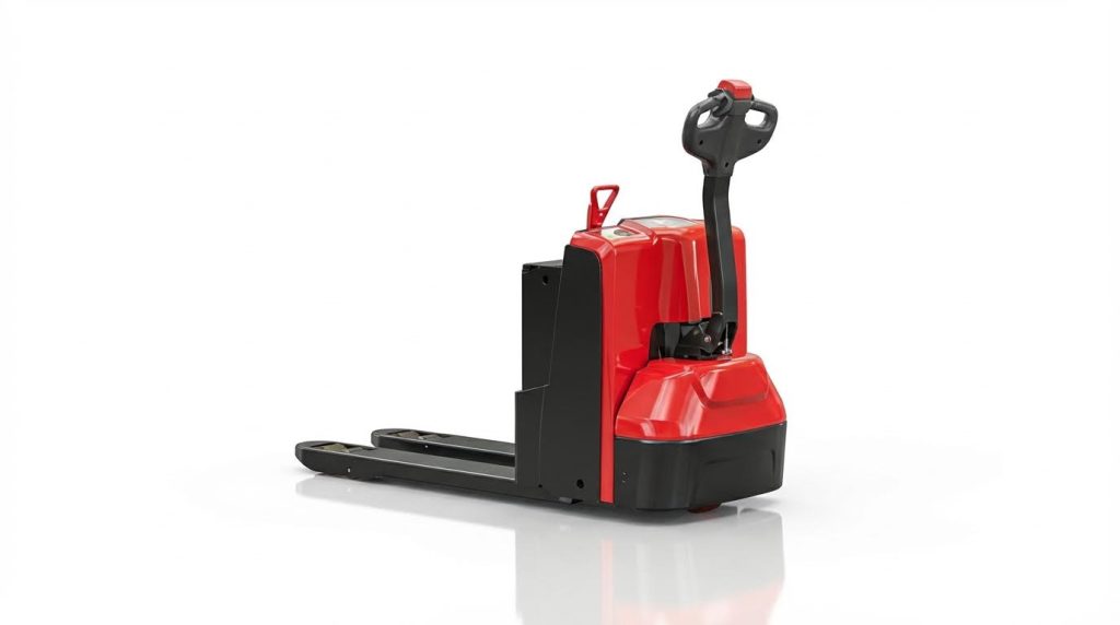
A pallet jack lifts using either hydraulic pressure or a screw mechanism. In the hydraulic version, a pump—either mounted on the baseplate or connected via a hose—generates pressure that pushes a hydraulic ram vertically out of the body to raise the forks. Hydraulic Jack Info. Manual pallet jacks use a handle-activated hydraulic pump to lift the load, while electric models rely on a motor for both lifting and propulsion.
Do pallet jacks use hydraulics?
Yes, most pallet jacks use hydraulics to lift loads. The hydraulic system is activated by a hand pump in manual pallet jacks or an electric motor in electric models. This system allows the forks to rise and lower smoothly, enabling efficient movement of palletized goods. Pallet Jack Types.
How high can a pallet jack lift?
Standard pallet jacks, both manual and electric, typically lift pallets to a height of around 6 inches (15 cm). However, specialized electric pallet jacks can lift up to 20 inches (50 cm) or more, depending on the model. These heights are sufficient for most warehouse operations. Lift Height Guide.