A straddle stacker should never be used on an incline because its four-point support, small drive wheel, and high mast geometry lose stability and traction as soon as the floor is no longer level. On slopes, the combined load and truck center of gravity shifts downhill, shrinking the safety margin until tip-over or roll-back becomes likely. This guide explains the physics behind that risk, the floor and ramp criteria involved, and which alternative equipment and layouts you should specify instead. You will see how to read gradients in %, translate them into real-world hazards, and redesign level changes so your operators never have to “make do” with the counterbalanced stacker again.
Why Straddle Stackers Are Designed For Flat Floors
Straddle stackers are engineered around the assumption of flat, level, high-friction floors, which is why a straddle stacker should never be used on an incline except under tightly controlled, manufacturer-approved limits. Their four-point support, small wheels, and tall mast geometry all depend on predictable contact with a near-zero slope surface.
Engineering practice kept indoor slopes within about 2–3% to preserve traction and prevent load shift for stacker-type equipment, and treated manufacturer gradient limits as absolute, not targets. Floors had to meet strict flatness and levelness criteria, often within roughly ±3–5 mm per 1 m, verified by laser or straightedge checks, to maintain lateral stability and consistent wheel loading. Engineering guidance also required clean, dry surfaces with a static friction coefficient around 0.4–0.6 to avoid traction loss and roll-back.
| Design Assumption | Typical Engineering Value / Range | Operational Impact For Straddle Stackers |
|---|---|---|
| Floor slope (indoor travel zones) | ≤ 2–3% gradient | Keeps CG projection inside support polygon and preserves drive-wheel traction on level changes. |
| Flatness / levelness tolerance | ≈ ±3–5 mm per 1 m | Prevents one outrigger lifting or unloading drive wheel on local highs/lows. |
| Joint height difference | < 2 mm at construction/expansion joints | Limits impact loads and sudden CG shifts when wheels cross joints. |
| Static coefficient of friction | ≈ 0.4–0.6 on dry floors | Provides braking and traction margin against roll-back on slight slopes. |
| Surface condition | Dry, clean, no loose dust/oil | Prevents sudden loss of grip that can turn a mild slope into an uncontrolled ramp. |
These numbers show that the “normal” operating envelope of a straddle stacker is essentially a very flat, well-maintained warehouse floor. Once you introduce noticeable inclines, rough joints, or low-friction patches, the original stability assumptions no longer hold, and tip or roll-back risk rises sharply.
💡 Field Engineer’s Note: In practice, I treat any visible slope combined with a wet or dusty patch as an incline hazard zone for straddle stackers, even if drawings say 2–3%; friction loss matters more than the theoretical gradient.
How Straddle Legs And Four-Point Support Work
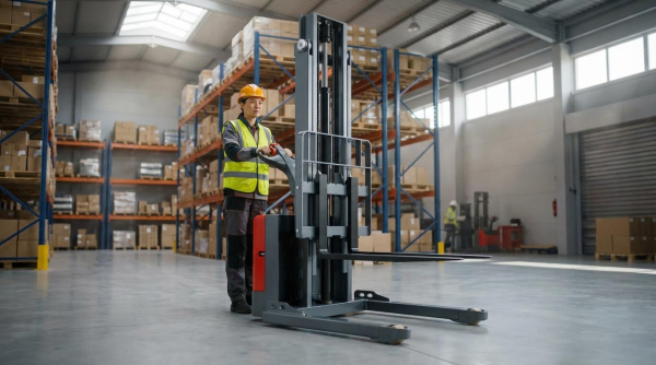
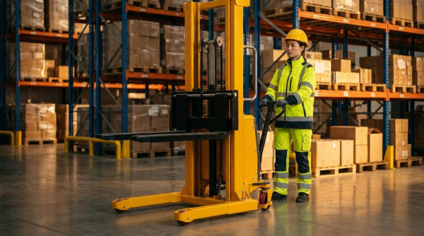
Straddle stackers use two low outriggers and two rear support points to create a four-point base that is only stable when all points sit on a flat, high-friction floor. The outriggers (straddle legs) project forward on either side of the pallet, while the drive wheel and a trailing caster or twin rear wheels sit behind the mast, forming a wide, roughly rectangular support polygon.
This geometry spreads load into the floor and allows the mast to lift pallets within the “straddle” without needing a heavy counterweight. On good floors, the outriggers carry much of the vertical load, while the drive wheel provides traction and braking. But this design assumes that each wheel sees a predictable share of the load. On slopes or uneven surfaces, load redistribution can partially unload the drive wheel or one outrigger, reducing friction and shrinking the effective support polygon.
- Forward outriggers: Carry pallet and mast load – Reduce floor pressure and allow narrow chassis without counterweight.
- Rear support points: Complete the four-point base – Provide longitudinal and lateral stability on flat floors.
- Small, hard wheels: Limit deformation – Roll easily on smooth concrete but amplify every mm of unevenness.
- Four-point contact: Stabilizes mast under rated load – Works only if all four points remain in firm floor contact.
On an incline, gravity shifts load downhill toward the lower outrigger and downhill rear support. This can unload the uphill wheels and, in extreme cases, lift one point clear of the floor, effectively turning a designed four-point system into a three- or two-point support. That is why a straddle stacker should never be used on an incline where wheel unloading or traction loss is possible, even if the gradient appears modest.
What happens if one wheel drops into a low spot?
If a low spot or shallow pit sits under the drive wheel or an outrigger, the truck can pivot around the remaining three points. This shrinks the support polygon and can move the combined center of gravity close to an edge, especially with a raised load, sharply increasing tip risk.
Center Of Gravity, Support Polygon, And Tip Lines
Straddle stacker stability depends on keeping the combined center of gravity (truck plus load) within the support polygon formed by the contact points of the two outriggers and the rear supports. On a flat, level floor, this polygon is a stable “safety envelope,” and the vertical projection of the center of gravity stays well inside it for rated loads at specified lift heights.
On an incline, the physics change immediately: the center of gravity shifts downhill, and its projection moves toward the downhill edge of the support polygon. As slope angle increases, the margin between the CG projection and the polygon edge (the tip line) reduces. Elevating the mast or extending the load pushes the CG higher and further downhill, so every additional millimeter of lift on a slope eats into the restoring moment that keeps the truck upright.
- Support polygon: Area enclosed by wheel and outrigger contact points – Defines the footprint within which CG must stay.
- Tip lines: Lines between two contact points – If CG projection crosses one, the truck will tip about that edge.
- CG height: Increases with mast extension and load elevation – Higher CG means less restoring moment against tipping.
- Incline effect: CG projection moves downhill – Reduces stability margin without any change in rated load.
Even small cross-slopes or uneven patches can shift the CG laterally toward one outrigger, shrinking lateral stability margins. When combined with a longitudinal slope, steering, or braking, the CG can approach a corner of the support polygon, where both longitudinal and lateral reserves are minimal. This is why industry guidance consistently warns that a straddle stacker should never be used on an incline for lifting, turning, or braking with an elevated load, and why best practice is to confine these trucks to very flat, well-controlled floors.
How do floor specs help keep the CG inside the polygon?
By limiting slopes to about 2–3%, flatness deviations to roughly ±3–5 mm per 1 m, and joint steps to below 2 mm, designers minimize unintended CG shifts and wheel unloading. Combined with a friction coefficient around 0.4–0.6 on clean, dry floors, these criteria keep the CG projection comfortably inside the support polygon during normal stacking operations.
Stability Failure Modes Of Straddle Stackers On Slopes
Straddle stackers have multiple ways to fail on slopes, which is why a counterbalanced stacker should never be used on an incline for routine handling. Even “small” gradients combine gravity shifts, traction loss, and dynamic effects that defeat their flat-floor design.
- Key Point: On any slope, the combined centre of gravity moves downhill – this shrinks the safety margin against tipping.
- Key Point: Four-point support and small drive wheels lose effectiveness on gradients – traction and braking become unreliable.
- Key Point: Cross-slopes and uneven floors turn small defects into major hazards – you can suddenly go from four wheels supporting to only two or three.
- Key Point: Braking, steering, and mast movement amplify all of the above – dynamic forces can push an already marginal situation over the edge.
💡 Field Engineer’s Note: If you must cross a level change with a straddle unit, treat it as an engineered exception: ultra‑shallow ramp (<2–3%), short length, verified friction (µ ≈ 0.4–0.6), and a strict rule that loads stay fully lowered.
Longitudinal Stability, Roll-Back, And Traction Loss
Longitudinally, straddle stackers on slopes lose restoring moment and drive-wheel grip, so roll-back and forward tipping become realistic failure modes even on modest gradients.
- Gravity Shift: On an incline the combined centre of gravity (truck + load) shifts downhill – its projection moves toward the downhill outrigger leg, cutting the stability margin.
- Support Polygon Effects: As the slope angle increases, the CG projection approaches the downhill edge of the support polygon – less torque is available to resist tipping.
- Four-Point Contact Breakdown: Load transfer can partially unload the drive wheel or one caster – traction drops, and the truck can slide or roll back even with the brake applied.
- Traction vs. Required Friction: Safe operation on flat floors already needs a static friction coefficient around 0.4–0.6 between wheels and floor for reliable braking and traction – on slopes, any oil, dust, or moisture can drop friction below what is needed to hold the load.
- Indoor Slope Limits: Engineering practice kept indoor slopes below about 2–3% for industrial trucks to preserve stability and traction – this is already a warning that a battery-powered stacker should never be used on an incline as a normal ramp truck.
- Roll-Back Risk: If the drive wheel is lightly loaded and friction is low, the truck can roll backward under a load – the operator may not be able to stop it by braking or body force.
- Overload And Load Position: Overloading or placing the load further forward increases the effective load centre downhill – this accelerates loss of longitudinal stability and roll-back risk.
Why “small” gradients are still dangerous
Even a 2–3% slope means a 20–30 mm height change over 1 m. With a tall, heavy pallet (for example 1,600–2,000 mm high and 800–1,200 kg), that small angle moves the combined CG several tens of millimetres downhill. On a narrow support polygon, that is often the difference between a safe and unsafe margin.
Lateral Instability, Cross-Slopes, And Uneven Floors
Laterally, even a slight cross-slope or local floor defect can shift support from four wheels to three or two, making side tipping the dominant risk when a straddle stacker is on an incline.
- Cross-Slope CG Shift: A cross-slope moves the CG sideways toward one outrigger leg – this shrinks lateral stability and raises the chance of side tip-over.
- Diagonal Travel: Moving diagonally on a ramp combines longitudinal and lateral components – the CG shifts both downhill and sideways, severely compromising stability.
- Flatness Criteria: Good practice limited floor flatness deviations to about ±3–5 mm per 1 m to keep lateral tilt under control – on a ramp, you often exceed these effective tilt limits once you add construction tolerances and wear.
- Joints And Local Defects: Height steps at joints were kept below about 2 mm for stacker operation to avoid impact and steering shocks – on a slope, a low spot under one outrigger can instantly convert four-point support into a three-point pivot.
- Three-Point And Two-Point Conditions: When one wheel lifts or drops into a depression, the effective support polygon shrinks – the CG can move outside this new, smaller polygon and cause a rapid side tip.
- Surface Contamination: Oil, water, and dust reduce friction well below the recommended 0.4–0.6 range even on level floors – on cross-slopes, this lets the truck slide sideways while the CG is already near the edge.
- Narrow-Aisle Sensitivity: Narrow straddle widths reduce lateral base – this makes any cross-slope or local defect more critical for side stability.
💡 Field Engineer’s Note: When investigating “mysterious” near-tips on very shallow ramps, I often found a combination of 2–3% ramp, 5–8 mm local floor depression, and a slightly cross-loaded pallet. The geometry stacked up, and the truck simply ran out of lateral margin.
How to evaluate a suspect ramp or transition
Measure: (1) main ramp gradient (%), (2) cross-slope across the truck’s width, and (3) local flatness over 1 m squares at the wheel paths. If any of these exceed the typical limits used for straddle stackers (about 2–3% slope and ±3–5 mm flatness per 1 m), treat the area as unsuitable for straddle units and redesign for other equipment.
Dynamic Effects: Braking, Steering, And Mast Extension
Dynamic effects on slopes push a marginally stable straddle stacker into failure, which is why manuals typically forbid turning, braking hard, or raising loads on ramps and why a straddle stacker should never be used on an incline as a lifting truck.
- Hard Braking: Sudden braking on a downgrade pitches the CG forward – this unloads the drive wheel, overloads the downhill outrigger, and can cause that wheel to lift or the truck to pivot.
- Load Height: Every millimetre of mast extension raises the CG and shifts it downhill on a slope – this rapidly erodes the restoring moment against tipping.
- Prohibition On Raising/Lowering: Operating guidance explicitly prohibited raising or lowering loads while on an incline and advised keeping forks low on ramps to avoid dynamic CG shifts – this is a strong engineering signal that the machine is not a ramp stacker.
- Steering Inputs: Turning on a slope adds lateral acceleration – this moves the effective CG toward the outside of the turn, combining with the downhill shift and increasing tip risk.
- Diagonal Travel Restrictions: Operators were instructed to avoid diagonal travel on ramps because it couples longitudinal and lateral instabilities – this restriction is rarely needed on equipment genuinely designed for ramp duty.
- Surface Transitions: Poorly designed transitions between level floors and ramps can create impact loads and pitching – this can momentarily unload one wheel set and destabilise the truck.
- Operator Reaction: In a near-loss event, operators often over-brake or over-steer – these instinctive actions add dynamic loads that can complete the tip-over.
💡 Field Engineer’s Note: When I model incidents in a digital twin, the static ramp angle alone almost never explains the tip. It is always “ramp + elevated load + quick stop” or “ramp + turn + floor defect” that pushes the CG just beyond the shrinking support polygon.
Practical operating rule set for any unavoidable slope
If a straddle stacker must cross a very shallow, short incline: keep the load fully lowered, travel straight (no diagonal), move at walking pace, and forbid any steering corrections or mast movement on the slope itself. Even then, treat this as a temporary workaround and plan for equipment or layout changes so that normal operations never depend on a straddle stacker working on an incline.
Safer Alternatives, Ramp Design, And Equipment Selection
This section explains what to use instead of straddle stackers on slopes, and how to design ramps and floors so you never need to argue about gradients in the first place.
If a straddle stacker should never be used on an incline in your operation, you either change the equipment, change the floor geometry, or both. The safest systems usually combine ramp redesign with trucks purpose-built for gradient work, or remove trucks from the incline entirely using lifts or conveyors.
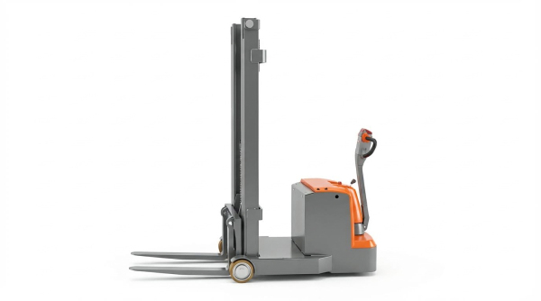
When To Specify Counterbalanced Or Center-Drive Stackers
You choose counterbalanced stacker or center-drive stackers whenever you must cross small level changes or imperfect floors and want to keep all ramp travel within the machine’s stable traction envelope.
Both options still prefer flat floors, but they tolerate gradients and surface defects better than straddle stackers whose outriggers lose contact or unload the drive wheel on slopes. The goal is not to “cheat” the rules; it is to select equipment whose geometry and weight distribution match your real gradients, joints, and contamination risk.
| Equipment Type | Key Geometry / Feature | Typical Use Case | Operational Impact On Slopes |
|---|---|---|---|
| Straddle stacker | Outriggers ahead of mast, four-point support | Short internal moves on flat, dry floors | High tip and roll-back risk on ramps; a straddle stacker should never be used on an incline for routine traffic |
| Counterbalanced stacker | Counterweight behind mast, no front outriggers | Dock interfaces, door thresholds, short indoor ramps | Improved longitudinal stability on moderate gradients; still needs low slopes and clean surfaces |
| Center-drive stacker | Drive wheel near truck CG, often with articulated or bogie load wheels | Imperfect floors, minor level differences, transitions | Better traction when surfaces are slightly uneven or joints unload one side |
| Wide-straddle with bogie wheels | Long wheelbase, multi-wheel bogies on outriggers | Rougher but essentially level floors | Improved contact over local depressions; does not fix basic incline instability |
- Counterbalanced stacker: Counterweight behind the mast – increases restoring moment against roll-back on gentle slopes.
- Center-drive stacker: Drive wheel near combined center of gravity – keeps traction when one side passes over a low spot or joint.
- Wide-straddle with bogies: Extra wheels in tandem – bridges cracks and local depressions without sudden wheel drop.
- Straddle stacker on ramps: Outriggers take more of the load as the CG shifts downhill – drive wheel unloads, brakes and traction degrade.
Whenever your travel path includes any sustained gradient, cross-slope, or rough joint, treat that as a design trigger: either eliminate the slope from the straddle stacker route, or specify counterbalanced / center-drive equipment dedicated to that ramp segment.
How to decide if you need a counterbalanced stacker
Walk the route the truck will follow. If you see dock plates, floor joints with noticeable steps, or any ramp longer than about 1–2 m, assume a straddle stacker is unsuitable and evaluate a counterbalanced stacker or center-drive alternative instead. Check the manufacturer’s rated gradient for loaded and unloaded travel and keep at least a 25–30% safety margin under real, measured slopes.
💡 Field Engineer’s Note: In many audits, “mystery” traction problems on ramps came from the outrigger wheels carrying most of the load. The drive wheel looked fine, but on a slope its vertical load dropped so far that even a high-friction floor could not generate enough braking force. Counterbalanced stacker or center-drive stackers keep the drive wheel loaded and predictable.
Ramp Geometry, Floor Criteria, And Non-Truck Solutions
You make inclines safer by keeping indoor gradients very shallow, smoothing transitions, enforcing floor friction targets, and ideally removing industrial trucks from the ramp with vertical lifts or conveyors.
Even when a manufacturer lists a maximum gradient, that value assumes ideal conditions: dry, clean floors, no cross-slope, no sudden joints, and disciplined operators. Real ramps almost never meet all of these assumptions. That is why engineering practice treats straddle stackers as flat-floor machines and pushes incline work to better-suited equipment or fixed systems.
| Design / Control Element | Typical Engineering Criterion | Operational Impact |
|---|---|---|
| Indoor ramp gradient | Keep within about 2–3% for routine industrial truck traffic Engineering practice | Maintains traction and minimizes CG shift; anything steeper should trigger alternative solutions. |
| Floor flatness / levelness | Approximately ±3–5 mm per 1 m for stacker lanes Flatness guidance | Reduces lateral CG swing and sudden wheel unloading on cross-slopes or dips. |
| Joint height differences | <2 mm at construction or expansion joints Joint quality | Limits impact loading and prevents sudden loss of wheel contact at joints. |
| Required coefficient of friction | Static μ ≈ 0.4–0.6 for safe operation Friction targets | Supports braking and hill-hold without drive-wheel slip on gentle slopes. |
| Surface cleanliness | No visible oil, standing water, or heavy dust in truck lanes Cleanliness criteria | Prevents μ from dropping below target; critical on any gradient. |
| Transition zones | Smooth vertical curves between level floor and ramp Ramp transitions | Prevents outrigger “see-sawing,” wheel hop, and shock loading on masts. |
- Ramp slope: Keep indoor ramps for trucks to 2–3% where possible – beyond this, look at lifts or conveyors instead of trying to “upgrade” a straddle stacker.
- Friction management: Maintain μ between 0.4 and 0.6 with regular tribometer checks – low friction plus a slope is a roll-back recipe.
- Surface repair: Fix cracks, potholes, and spalled joints – local depressions can briefly turn four-point support into two-point, especially dangerous on slopes.
- Wheel / floor pairing: Match polyurethane or rubber compounds to the floor type – enough grip without destroying coatings or tiles.
Non-truck options for level changes
Where gradients would exceed safe limits, replace truck travel with fixed systems. Vertical conveyors or platform lifts handle pallet elevation without any ramp. Incline or steep-incline conveyors move cartons or bulk goods between levels with controlled angles and containment, using cleats or sidewalls when angles exceed roughly 30° to prevent rollback or spillage. These solutions remove human operators from the incline and turn a high-risk ramp into a guarded, automatic system.
For many mezzanine or dock-to-floor interfaces, the safest answer is to avoid ramps entirely. A short vertical lift or an inclined conveyor can bridge 3–6 m of height change in a footprint far smaller than a compliant ramp, and with far better control of load behavior on the incline.
💡 Field Engineer’s Note: When you calculate how long a 2–3% ramp must be to climb even 1 m, you often discover it will not physically fit without cutting into storage space or doors. That is usually the turning point where facilities accept that a straddle stacker should never be used on an incline there and commit to a vertical lift or conveyor instead.
Final Thoughts On Safe Handling Across Level Changes
The physics in this guide all point to one clear rule: treat straddle stackers as flat-floor machines only. Their four-point geometry, small hard wheels, and tall masts depend on level, smooth, high-friction floors to keep the center of gravity inside a stable support polygon. As soon as you add slope, cross-fall, joints, or dynamic actions like braking and steering, that safety envelope shrinks fast.
On inclines, the drive wheel can unload, traction falls, and the truck may roll back or tip with little warning. Good engineering practice therefore shifts incline work to better-suited equipment and infrastructure. Use counterbalanced or center-drive stackers, such as Atomoving solutions, where gradients and imperfect floors cannot be avoided, and verify that ramp and floor geometry stay well inside their rated limits.
Where slopes would exceed about 2–3%, redesign the route. Replace long ramps with vertical lifts or conveyors and keep people and stackers off steep inclines entirely. The best operations do not rely on operator skill to “get away with it.” They match truck design, floor criteria, and gradient to create a system where unsafe combinations simply never occur.
Frequently Asked Questions
Can a straddle stacker be used on an incline?
A straddle stacker should never be used on an incline. This is because the stability of the stacker is compromised on slopes, increasing the risk of tipping over. The center of gravity can shift, making it difficult to control and potentially leading to accidents. Always operate straddle stackers on flat surfaces to ensure safety. Safety Guidelines.
What is a straddle stacker used for?
A straddle stacker is designed to easily maneuver pallets through tight spaces in warehouses or facilities. It features two support legs that extend on either side of the pallet, allowing for efficient handling in confined areas. This makes it ideal for operations where space is limited. Warehouse Equipment Guide.
What should you do before using a straddle stacker?
Before operating a straddle stacker, conduct thorough pre-operation safety checks. Inspect the equipment for damages, check fluid levels, and ensure all safety features are functioning properly. These steps help prevent accidents and maintain efficient operation. Safety Tips.