
Scissor lifts relied on precise electro‑hydraulic control, robust safety systems, and disciplined maintenance to operate safely. This guide covered core operating principles and control logic, including power-up sequencing, platform travel, steering, and emergency descent within the defined load and stability envelope. It then structured troubleshooting of electrical, hydraulic, sensor, and motor faults into a systematic workflow that aligned with field-proven diagnostic practices. Finally, it linked preventive inspections, battery care, and emerging self-diagnostic tools to safer, more reliable, and more efficient scissor lift operation across the machine’s lifecycle.
Core Operating Principles And Control Functions
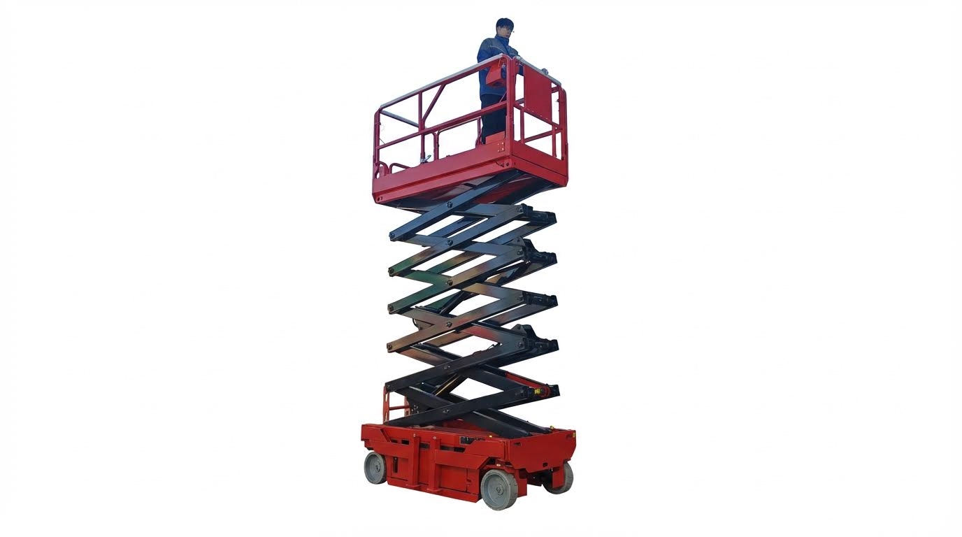
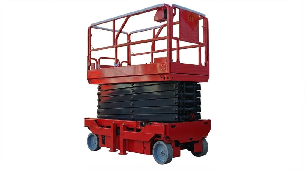
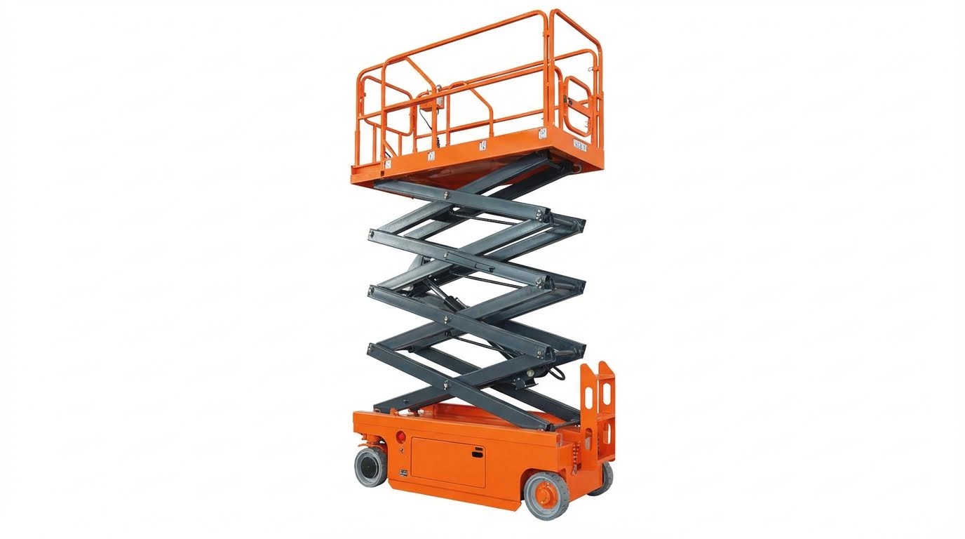
Core operating principles for scissor lifts centered on controlled power distribution, redundant safety interlocks, and clearly segregated base and platform controls. Modern electric and hydraulic self-propelled units used keyed selectors to choose ground or platform control, with total power switches isolating the battery pack for maintenance and emergency conditions. Understanding how lift, drive, and steering logic interacted with load limits and stability envelopes allowed technicians and operators to diagnose faults faster and operate within regulatory safety margins.
Power-Up Sequence And Base Controls
The power-up sequence typically began at the battery isolation or “total” switch, which had to be on before any control circuit energized. Operators then selected the base controller using the key switch, usually by turning it to the left or to the “ground” position. Only after this selection did raise and lower push-buttons at the chassis become active for vertical motion. Safe practice required confirming indicator lights, battery level display, and emergency stop status before any lift command. If the machine did not respond, technicians checked the main power switch, key switch, Anderson connectors, battery cables, and ground connections for continuity and damage. Following the manufacturer’s sequence in the user manual reduced nuisance faults and avoided ECU or PCU communication errors during startup.
Platform Controls, Travel, And Steering Logic
Platform controls typically provided full lift, drive, and steering functions once the key switch assigned priority to the upper console. A dedicated enable or function button, such as button 3, had to be pressed while moving a proportional control bar or joystick to raise or lower the platform. Moving the bar forward raised the lift, while pulling it back lowered it, provided all interlocks and sensors reported safe conditions. Travel logic usually required pressing a separate drive button, such as button 4, then moving the same bar forward or backward to move the machine in the corresponding direction. Speed selection used a distinct control, like button 5, to toggle between low and high travel speeds, supporting precise positioning at height and faster travel at stowed height. Steering commands came from buttons or a joystick axis above the bar, with the left button turning left and the right button turning right. This architecture separated enable, lift, drive, and steer functions to minimize inadvertent movement and supported clear fault isolation when a single function failed.
Emergency Stop, Descent, And Manual Lowering
Emergency stop devices interrupted the control circuit and often the main power relay, immediately disabling lift and travel functions. Operators had to verify that all emergency stop buttons were released before diagnosing non-responsive controls. For emergency descent, dedicated controls such as NO. 9 allowed the platform to lower under controlled hydraulic flow when normal commands failed. Manufacturers also provided manual lowering valves at the base manifold, enabling ground personnel to lower a raised platform during power loss or ECU failure. Procedures required returning all controllers to the zero position if power was interrupted before or during operation, preventing unexpected motion on re-energization. After any emergency descent, technicians inspected hydraulic, electrical, and sensor systems before returning the lift to service.
Load Limits, Stability, And Work Envelope
Scissor lifts relied on strict adherence to rated load capacity and defined work envelopes to maintain stability. Operators had to keep total platform load, including personnel, tools, and materials, at or below the manufacturer’s specified mass in kilograms. Exceeding this limit risked triggering overload (OL) alarms, reduced function, or potential structural and stability hazards. Tilt or level sensors monitored chassis inclination; an LL alarm on apparently level ground indicated a faulty inclination switch or incorrect calibration, which required measurement of the output signal and reset on a verified horizontal surface. A safe overhead clearance above the work platform had to be maintained to avoid entrapment and collision with structures or utilities. During lifting or lowering, no part of an operator’s body was allowed to extend beyond the guardrails, and the chassis had to rest on firm, level ground with support legs or outriggers correctly deployed and locked. Understanding these constraints helped operators stay within the safe work envelope and gave maintenance staff clear diagnostic cues when overload or tilt interlocks inhibited motion.
Systematic Troubleshooting Of Common Faults
Systematic troubleshooting of scissor lifts relied on a structured, safety-first approach. Technicians minimized guesswork by separating electrical, hydraulic, sensor, and drive issues and validating each subsystem step by step. Modern self-propelled electric scissor lifts used integrated ECUs, PCUs, and sensor networks, which required both multimeter-based checks and controller diagnostics. A consistent method reduced downtime, prevented repeat failures, and supported regulatory compliance for powered access equipment.
No Lift Or Travel: Electrical And Control Checks
When a lift did not raise or travel, technicians first confirmed power availability and control interlocks. They verified the main power switch and key switch positions, checked battery voltage under load, and inspected Anderson connectors and ground cables for looseness or corrosion. If indicator lamps, ECU, and PCU displays remained dark, the fault usually lay in the primary power path or key circuit. When the platform did not move after pressing the “up” or “down” buttons, both hydraulic and electrical sides required checking for tripped interlocks, overloads, or open circuits. Technicians inspected wiring harnesses at articulations for damage, tested continuity through limit and emergency stop circuits, and confirmed that control handles returned correctly to the zero position after any power interruption.
Hydraulic Faults: Noise, Overheating, And Leakage
Hydraulic faults often appeared as abnormal noise, rapid oil temperature rise, or visible leaks. Excessive pump noise suggested cavitation, low oil level, blocked suction strainers, or aerated fluid, which required immediate shutdown and inspection. Rapid temperature increase indicated overloaded operation, stuck valves, or internal leakage across cylinders, all of which reduced efficiency and risked seal failure. Any external oil leakage at hoses, fittings, or cylinders compromised environmental compliance and slip safety and had to be corrected before returning the lift to service. If the platform jumped, jammed, or moved erratically during lifting, operators were instructed to stop the machine, relieve pressure, and have a qualified technician inspect valves, flow control devices, and structural alignment of the scissor pack.
Sensor, Limit Switch, And ECU Diagnostic Steps
Electronic controls depended on accurate sensor and limit switch feedback to enforce safety envelopes. Frequent “LL” tilt alarms on level ground required measuring the inclination switch output and resetting or replacing it on a calibrated horizontal reference. Repeated overload “OL” alarms without load pointed to misaligned angle or pressure sensors, unstable supply voltage, or incorrect weighing calibration; technicians recalibrated zero-load and full-load points per the manufacturer’s procedure. Intermittent control actions, where switches appeared normal on a multimeter yet commands did not register, often traced to weak spring return in limit switches or poor terminal contact at the ECU connector. For controller communication faults such as recurring “02” errors, diagnostic steps included reseating PCU and handle connectors, checking harness integrity, verifying termination, and, if necessary, replacing the handle or lower control ECU and re-powering to confirm restoration.
Intermittent Drive, Fault Codes, And Motor Issues
Intermittent drive or steering issues manifested as unstable travel speed, unexpected stopping, or delayed response. Technicians correlated fault codes from the controller with observed behavior, then checked speed control signals and drive enable interlocks. Poor contact in wiring harnesses, especially at moving joints, caused fluctuating motor commands and had to be corrected through repair or replacement rather than temporary adjustment. When motors ran hot, produced sparks, or showed inconsistent torque, inspection of carbon brushes, commutators, and slip rings, as well as bearing condition, became essential. If the controller powered up but the motor did not run, technicians verified that command inputs reached the controller, checked output stages with a multimeter under simulated commands, and ruled out short circuits or open phases before authorizing component replacement.
Preventive Maintenance And Inspection Practices

Preventive maintenance for scissor lifts relied on structured inspections, disciplined record keeping, and adherence to manufacturer requirements. A robust program reduced unplanned downtime, extended component life, and improved safety margins at height. The following subsections outline practical routines that aligned with typical ANSI/CSA and CE maintenance expectations.
Daily Pre-Use Checks And Function Testing
Operators performed a walk‑around inspection before every shift. They checked for hydraulic leaks, visible damage, loose fasteners, and contamination on platforms and steps. Guardrails, gates, emergency stops, and tilt or overload alarms had to operate correctly before the lift entered service. Tires, wheels, and brakes required inspection for wear, damage, and secure mounting on firm, level ground. A function test followed in a clear area, verifying lift, lower, drive, steering, and horn responses from both base and platform controls. Any abnormal noise, jerky motion, or delayed response triggered removal from service and technical inspection.
Monthly And Annual Inspection Requirements
Monthly inspections were more detailed and usually performed by maintenance technicians. They assessed structural members, scissor arms, welds, centering links, and guardrail posts for cracks, deformation, or corrosion. Electrical harnesses, connectors, and switches were checked for insulation damage, chafing at articulations, and secure terminations. Annual inspections required a qualified person and included load testing to rated capacity, verification of safety devices, and documentation for regulatory compliance. These inspections confirmed conformity with applicable standards and local occupational safety regulations. Findings from monthly and annual checks fed into repair plans and component replacement schedules.
Battery Care, Charging Protocols, And Monitoring
Battery health directly affected lift performance, duty cycle, and fault rates. Daily tasks included parking the machine on level ground, lowering the platform, turning the key off, removing it, and connecting the approved charger. Charging occurred in a ventilated area, using only chargers and batteries specified for the model, with battery compartments opened when required by the manufacturer. Wet cell batteries needed electrolyte level checks with appropriate PPE and topping up with distilled water before charging. Operators monitored onboard battery indicators and removed the lift from service when charge dropped to the defined limit, avoiding repeated short “opportunity” charges that shortened service life. Well‑maintained lead‑acid batteries typically lasted up to three years, while advanced monitoring systems extended life by tracking state‑of‑charge, temperature, and charge history.
Integrating Self-Diagnostics And Digital Twins
Modern electric scissor lifts increasingly incorporated self‑diagnostic functions in their controllers. These systems logged fault codes, monitored sensor signals, and displayed clear alarms for issues such as tilt, overload, or communication loss. Maintenance teams used these diagnostics alongside digital maintenance records to identify recurring faults and plan interventions. Some advanced platforms used digital twins or detailed virtual models of the lift to simulate load cases, predict component fatigue, and optimize service intervals. Integration of real‑time data from battery monitoring, motor controllers, and sensors into fleet management software improved availability and reduced unplanned stoppages. As all‑electric architectures with fewer hydraulic components spread, preventive maintenance shifted toward electronics, software configuration, and data‑driven condition monitoring.
Summary: Safe, Reliable, And Efficient Lift Operation
Safe, reliable scissor lift operation depended on three pillars: correct control use, structured troubleshooting, and disciplined maintenance. Operators first had to understand power-up sequences, base and platform controls, emergency descent functions, and the relationship between load limits, stability, and the work envelope. Only trained personnel were allowed to operate, with mandatory harness use, body kept inside guardrails, and strict adherence to manufacturer procedures and rated capacities.
When faults occurred, a systematic diagnostic approach reduced downtime and prevented unsafe improvisation. Technicians started with electrical supply and control logic, then moved to hydraulic performance, and finally to sensors, limit switches, and ECU parameters. Typical issues such as no lift or travel, 02 communication failures, LL or OL alarms, and intermittent drive required targeted checks of wiring harnesses, connectors, limit contacts, motor assemblies, and controller configurations. Accurate fault interpretation and verification with instruments such as multimeters and inclination sensors were essential for root-cause correction.
Preventive maintenance formed the long-term backbone of safe operation. Daily, monthly, and annual inspection regimes, aligned with standards such as ISO 16368 and regional occupational safety regulations, ensured structural integrity, hydraulic tightness, electrical reliability, and functional safety of emergency systems. Robust battery care and charging protocols, combined with emerging technologies such as advanced battery monitoring, self-diagnostics, and all-electric platforms, reduced life-cycle costs and environmental risk by eliminating hydraulic leaks. Going forward, integration of digital twins and connected diagnostics would enhance predictive maintenance, but organizations still needed clear procedures, documented inspections, and competency-based training to realize these benefits. A balanced strategy that combined proven mechanical practices with modern electronic monitoring offered the highest assurance of safe, reliable, and efficient scissor lift operation throughout the asset life.

