
Scissor lifts relied on integrated electrical, hydraulic, and structural systems that demanded disciplined troubleshooting and safe operating practices. This article outlined core system failures, hydraulic circuit diagnosis using modern 3D schematic tools, and structured recovery methods for manual operation and emergency descent. It connected practical fault-finding steps with real-world safety procedures, regulatory expectations, and manufacturer guidance. Readers used it as a compact reference for diagnosing no-lift or no-drive problems, interpreting hydraulic schematics, and operating scissor lifts safely under both normal and abnormal conditions.
Core Systems And Common Scissor Lift Failures

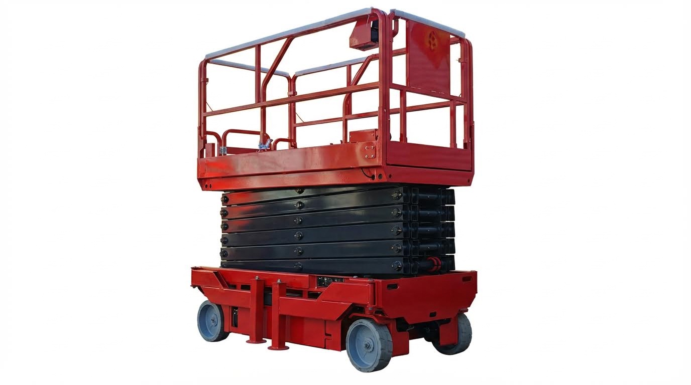
Scissor lifts relied on tightly integrated electrical and hydraulic systems. Most field failures traced back to a small set of recurring issues in these core subsystems. Structured diagnostics reduced downtime and prevented unnecessary parts replacement. Understanding how faults manifested in each system allowed technicians to isolate root causes quickly and safely.
Electrical Vs. Hydraulic Faults: First Diagnostics
Technicians typically distinguished electrical from hydraulic faults during the first diagnostic pass. If the platform controls remained dead, indicator lights stayed off, or the emergency stop latched, an electrical issue was likely. If controls powered up and solenoids clicked but the lift failed to move or build pressure, the fault usually lay in the hydraulic circuit. Initial checks included verifying battery voltage, main fuses, key switch position, and E-stop status, then confirming pump motor operation. A simple test was to listen and measure: if the pump motor did not run when commanded, the issue was electrical; if it ran but pressure and motion were absent, hydraulic components such as relief valves, directional valves, or pump output required inspection.
Typical No-Lift, No-Drive, And Slow Operation Issues
No-lift conditions often resulted from open safety circuits, failed lift solenoids, or insufficient system pressure. Technicians checked for active fault codes, verified that platform and base controls were not both selected, and confirmed that the lift enable circuit closed. No-drive complaints frequently traced to elevated platform lockouts, tilt sensor inputs, or drive speed interlocks that prevented motion when the lift was raised. Slow operation typically indicated low battery voltage, high circuit resistance at contactors, clogged hydraulic filters, or partially stuck proportional valves. Measuring voltage drop under load and comparing hydraulic pressure to specification helped separate electrical supply limitations from hydraulic flow restrictions.
Interlocks, Limit Switches, And Load Sensor Problems
Interlocks and limit switches protected the structure and occupants but often caused nuisance no-function faults when misadjusted. Upper limit switches prevented over-raising the platform; if they failed closed, the lift would not extend even from the stowed position. Drive interlocks linked to platform height and steering angle enforced reduced speed or complete drive inhibition at elevation. Load sensors and pressure-based load sense valves monitored platform capacity and could inhibit lift or trigger alarms when overload conditions existed. Faulty or contaminated load sensors sometimes falsely reported overload, so technicians compared sensor readings to actual measured load and checked wiring continuity. Proper calibration and mechanical alignment of switches and sensors were critical to avoid intermittent cutouts and unexplained shutdowns during operation.
Battery, Charger, And Power Supply Failures
Battery and charger problems represented a major source of scissor lift downtime. Undercharged or sulfated batteries caused voltage sag under load, leading to sluggish lift speeds, reduced drive torque, and frequent low-voltage cutouts. Technicians measured open-circuit voltage, specific gravity where applicable, and loaded voltage during pump operation to assess battery health. Chargers that were not matched to battery type or that had failed control boards left packs chronically undercharged, shortening service life. Corroded terminals, loose lugs, and damaged cables increased resistance and generated heat, further reducing available power. Preventive maintenance included cleaning terminals, torque-checking connections, verifying charger output against nameplate values, and ensuring operators recharged electric units after each shift rather than deep-cycling them to failure.
Hydraulic Circuit Diagnosis And 3D Schematic Tools
Hydraulic diagnosis on scissor lifts relied on clear understanding of circuit architecture. Technicians compared actual pressures, flows, and actuator responses against schematic intent. Modern 3D schematic tools enhanced this process by visualizing components in spatial context and linking them to parts data.
Reading Hydraulic Schematics For Scissor Lifts
Technicians first identified the power source, usually an electric motor driving a gear or vane pump. They then traced the pressure line from pump outlet through main relief valves, directional control valves, and finally to lift and drive cylinders. Symbols for check valves, flow controls, and counterbalance valves indicated how the system controlled motion, prevented drift, and held loads. Correct diagnosis required correlating schematic sections to physical locations, such as base frame manifolds, platform-mounted valves, and ground control blocks.
Scissor lift schematics typically separated functions into lift, steer, and drive circuits sharing a common reservoir and return manifold. Color-coded line types distinguished pressure, return, and pilot lines, which reduced misinterpretation during troubleshooting. Technicians verified suspected faults by measuring pressure at test ports shown on the schematic and comparing values to the service manual. Accurate schematic reading minimized unnecessary component replacement and reduced downtime.
Using JLG 3D Hydraulics For Fault Isolation
JLG’s 3D hydraulic schematics tool allowed users to select a specific machine model or search by serial number or PVC code. Once loaded, the 3D rendering displayed the actual machine layout with hydraulic components mapped to functional circuits. Users could hide major structures, such as hoods or covers, to expose ground control panels, valve blocks, and hose routings. This capability simplified locating hard-to-see valves or manifolds that traditional 2D drawings sometimes obscured.
The interface displayed circuit flows such as suction, pump discharge, return, and electrical inputs to solenoid valves using distinct colors and a legend. Technicians could double-click any component to center it and then rotate, zoom, or make the model transparent for better visualization. Swing-left and swing-right highlight tools emphasized specific hydraulic functions in color, improving understanding of how motion commands propagated through the circuit. This visual mapping helped isolate whether faults originated in the pump group, control valves, interlocks, or actuators.
Tracing Hoses, Valves, And Ports In Dense Circuits
Dense scissor lift circuits contained numerous hoses routed through tight chassis spaces and scissor stacks. In the 3D hydraulic environment, users isolated individual hoses or groups by toggling component visibility on the left-hand panel. They could follow a hose from a valve port to a cylinder or manifold by visually tracking the highlighted path. Color-coded hose types and a legend reduced confusion between pressure, return, and pilot lines.
Technicians used this capability to verify correct hose connections after component replacement or major repairs. They compared port labels in the 3D model with markings on physical valve bodies and cylinders. Zoom and expand tools allowed inspection of port orientations and tee connections that were difficult to see in the field. Accurate tracing prevented crossed lines, which could cause reversed functions, uncontrolled lowering, or no-lift conditions.
Selecting And Ordering Correct Replacement Parts
The 3D schematics linked every visible hydraulic component to a part number and description. When technicians hovered over a valve, hose, or fitting, the interface displayed its identifier and functional name. Clicking the part number added it directly to the Online Express shopping cart, which reduced transcription errors from paper lists. This integration ensured that ordered parts matched the exact serial-number configuration of the machine.
Users accessed the “manual” tab to open the Parts, Service & Maintenance, and Operation & Safety manuals for the selected model. They cross-checked exploded views and parts lists against the 3D model to confirm revisions, such as superseded valves or updated hose assemblies. This workflow supported regulatory compliance by helping maintain original performance specifications and load-holding capabilities. Correct part selection also reduced repeat failures caused by incompatible seals, incorrect pressure ratings, or non-OEM fittings.
Manual Operation, Recovery, And Emergency Descent

Pre-Operation Checks And Safety Interlocks
Operators performed a structured pre-operation inspection before any manual operation. They checked tires, wheels, and chassis for damage, correct inflation, and hydraulic leaks around hoses and cylinders. They verified guardrails, gates, chains, and toe boards for integrity and correct latching, because interlocks often depended on properly closed doors. They inspected the platform and base control panels, confirming that emergency stop (E‑Stop) buttons latched and released correctly. They also confirmed battery charge or fuel level, as low power frequently caused nuisance faults or incomplete emergency descent. Safety interlocks, such as gate switches, tilt sensors, load sensors, and key selector switches, were tested functionally against the operator’s manual. Any failed interlock or unexplained warning indicator required locking out the machine and calling a qualified technician.
Platform Controls, Drive Modes, And Speed Limits
Safe manual operation relied on understanding the platform control hierarchy. Operators selected the platform control position on the base “off / platform / base” key switch, then armed the system by releasing both E‑Stops. They confirmed the platform fully lowered before selecting drive mode, because most scissor lifts locked out drive at height or sharply reduced speed. Horizontal function selectors typically switched between lift mode and drive mode, while vertical selectors adjusted speed between low and high ranges. Operators kept speed in low range for tight areas, ramps at ground level, and precise positioning. They used the joystick for proportional lift and drive, pushing forward to raise or move forward and pulling back to lower or reverse. Turning used a thumb or rocker switch on the joystick, and operators allowed the lift to stop fully before reversing direction to avoid instability. They never drove with the platform elevated unless the manufacturer explicitly allowed it at restricted speed and on level, unobstructed ground.
Manual Lowering, Release Valves, And E-Stops
Emergency descent procedures depended on correctly using E‑Stops and manual lowering devices. Pressing any E‑Stop immediately removed power to hydraulic and drive functions, stopping motion but not automatically lowering the platform. To lower a stuck elevated platform, a trained person at the base located the manual lowering valve or pull cable indicated in the service or operator’s manual. They actuated the valve slowly to bleed pressure from the lift cylinder circuit, keeping visual contact or communication with personnel on the platform. The platform descended under its own weight at a controlled rate if the valve opened gradually. Operators avoided holding the valve fully open, which could cause a rapid drop. After use, they reset the valve to its normal closed position and documented the incident for maintenance follow-up. E‑Stops remained engaged until the hazard cleared; only then did operators pull them out and re-energize controls for diagnostic checks.
Procedures When Power Or Controls Are Lost
Loss of power or control required a calm, predefined response. If the platform controls failed while elevated, the operator first engaged the platform E‑Stop and notified ground personnel. Ground staff then switched the key to base control, attempted normal powered lowering, and checked for tripped breakers, loose connectors, or an obvious battery or charger fault. If powered lowering was unavailable, they followed the manufacturer’s emergency descent procedure, using the manual lowering valve or hand pump where fitted. They maintained clear communication using radios or agreed hand signals, confirming that the area under the platform was clear before descent. In cases of complete electrical failure with trapped personnel, rescue planning followed site procedures and local regulations, which could include using another lift or fire service. After any power-loss event, the lift was removed from service, tagged, and inspected by a qualified technician to identify root causes such as failed contactors, damaged wiring, or defective control modules before returning it to operation.
Summary Of Best Practices And Future Trends
Scissor lift troubleshooting and safe manual operation relied on disciplined diagnostics, structured inspections, and strict adherence to manufacturer instructions. Effective fault finding started with separating electrical from hydraulic causes, then checking interlocks, limit switches, batteries, chargers, and hydraulic circuits in a logical sequence. 3D hydraulic schematic tools, such as JLG’s Online Express system, improved accuracy by allowing technicians to visualize circuits, isolate components, and order correct parts directly from the model. Safe operation in parallel required pre-use inspections, stable ground conditions, correct load management, and consistent use of personal protective equipment and fall protection.
Industry data indicated that organizations with formal maintenance programs and checklists experienced significantly fewer equipment-related incidents. This pushed fleets toward preventive maintenance, digital service records, and standardized pre-operation checklists covering hydraulics, structure, controls, and safety devices. Regulatory frameworks, including OSHA requirements for fall protection and platform guardrails, continued to shape design features such as interlocked gates, emergency stops, and load sensing systems. Manufacturers integrated additional safeguards like automatic brakes, explosion-resistant hoses, and diagnostic systems to reduce the consequences of operator error and component failure.
Future trends pointed to deeper digital integration. 3D schematics, remote diagnostics, and connected telematics were evolving toward real-time condition monitoring and predictive maintenance. Technicians increasingly relied on interactive documentation, serial-number-specific manuals, and guided troubleshooting workflows. For users, interfaces were moving toward clearer human–machine interaction, with simplified mode selection, speed limiting, and more intuitive emergency controls. The most robust implementation strategy combined these technologies with rigorous training, certification, and procedural discipline, ensuring that advances in design and software translated into measurable gains in safety, uptime, and total lifecycle cost.
