Moving a disabled scissor lift combined mechanical risk, stability challenges, and regulatory obligations. This article examined safety fundamentals, mechanical movement methods, and transport engineering for non-running units. It covered brake-release and freewheeling principles, winch and towing techniques, and how ground conditions affected load paths. The final sections integrated trailer selection, tie-down design, electrical isolation, route planning, and a concise summary of best practices for moving dead scissor lifts safely.
Safety Fundamentals Before Moving a Dead Scissor Lift
Risk Assessment and Lockout/Tagout Steps
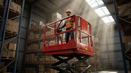
Before moving a non-running scissor lift, the team should perform a structured risk assessment. They should identify gradient, surface condition, proximity to traffic, and overhead obstructions. The assessment should also consider machine mass, center-of-gravity height, and available restraint methods. Operators should review the manufacturer’s manual for model-specific hazards and emergency procedures. Lockout/tagout started with powering the machine off and removing the key. For electric units, technicians should open the main disconnect and, if specified, disconnect the battery to prevent energization during handling. They should tag the controls and isolation points with clear warnings stating “Do Not Operate – Under Maintenance or Tow.” Only a designated person in charge should remove lockout devices after the move and inspection.
Stabilizing the Machine and Scissor Stack
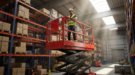
Before any brake release or towing, the lift should sit on firm, level ground. Operators should verify that the platform and scissor stack are fully lowered and mechanically stable. This reduced the center of gravity and minimized overturning risk during pushing or winching. Where the design allowed, transport or lift locks should engage to prevent unintended elevation. Wheel chocks rated for the machine’s weight should be placed on downhill sides and, on slight slopes, on both sides of at least two wheels. Personnel should remove loose tools, guardrails, or components or secure them with ties or storage boxes. If the lift had visible structural damage, hydraulic leaks, or bent scissor members, it should not be moved without engineering review or auxiliary support equipment such as cranes or forklifts.
Understanding Freewheeling and Brake-Release Hazards
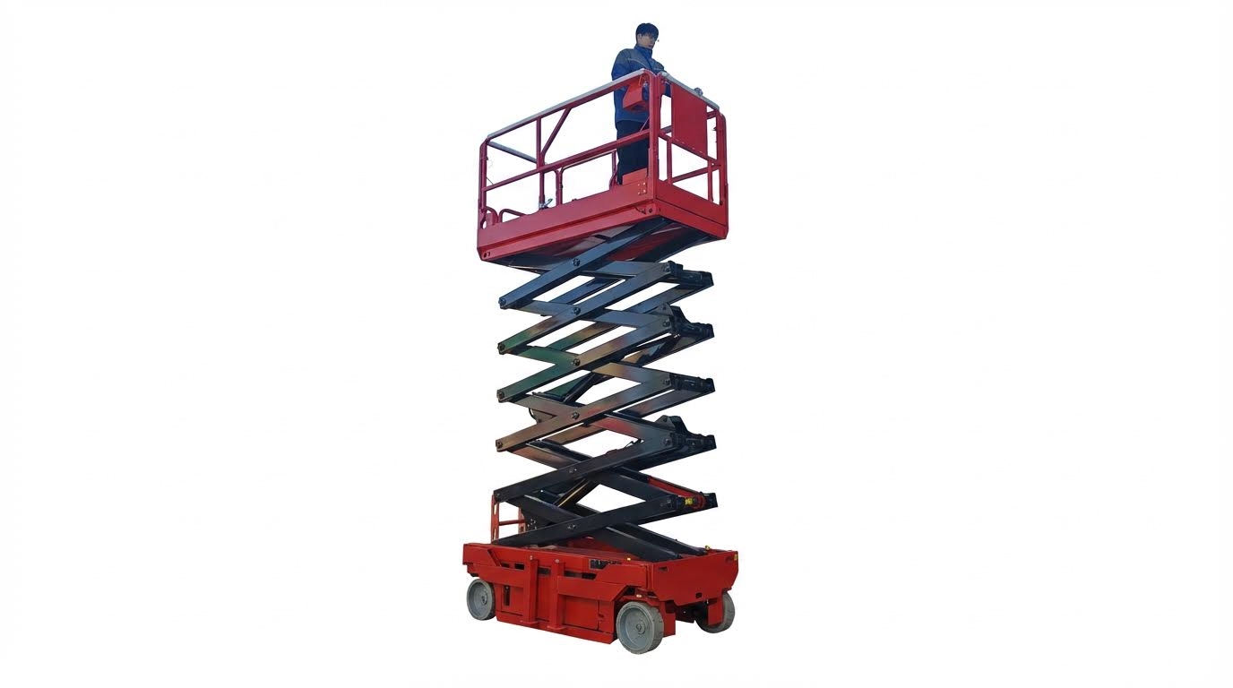
Freewheeling and brake-release functions allowed the wheels to roll with minimal resistance when the drive system was disabled. On most scissor lifts, a brake release valve and freewheeling valve sat on the main hydraulic manifold. Opening these valves or using a brake release pump removed spring-applied braking force and connected hydraulic circuits between drive motors. Once released, the platform could roll freely, which created a high run-away risk on even slight slopes. Therefore, personnel should only release these systems on level, chocked ground with a clear, controlled path of travel. They should keep body parts out of pinch points and never stand directly downhill of the machine. After relocation, technicians should close the freewheeling valve, reset the brakes per the manual, and verify drive and brake function before returning the lift to normal service.
When to Call a Qualified Service Provider
Operators should call a qualified service provider when procedures exceed the scope of the operator’s manual or site competence. Situations included structural damage, suspected frame distortion, or entrapment of the scissor stack in overhead steel. Units on significant slopes, soft ground, or confined spaces often required engineered rigging plans and specialized equipment. If brake or freewheeling valves were not clearly identified, or if the emergency move instructions prohibited towing without specific kits, technicians should not improvise. Service providers with manufacturer training could interpret model-specific schematics, apply correct hydraulic isolation steps, and select appropriate winches or lifting equipment. In jurisdictions with strict lifting-equipment regulations, engaging certified aerial-work-platform technicians also supported legal compliance and proper documentation of repairs and inspections after the move.
Mechanical Methods to Move a Non-Running Scissor Lift
Mechanical relocation of a disabled scissor lift required strict control of braking, traction, and stability. Engineers and operators minimized uncontrolled motion by using designed brake-release systems, controlled towing forces, and verified load paths. The goal was to move the unit only far enough to reach a safe maintenance or transport position, without exposing personnel to roll-away or tip-over hazards.
Locating and Operating Brake Release and Tow Valves
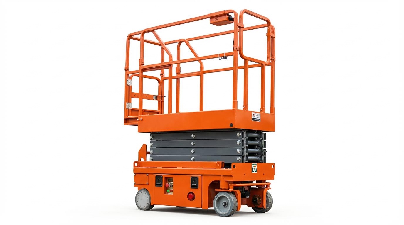
Manufacturers typically located brake release and freewheeling valves on the main hydraulic manifold or near the drive hubs. The brake release pump generated hydraulic pressure to overcome spring-applied brake packs, while the freewheeling valve allowed oil to bypass the drive motors, so wheels rolled with low resistance. Before operating these devices, the lift had to sit on flat, level ground with wheels chocked or otherwise restrained, because once released, the machine could move freely without service brakes. Technicians followed the operator’s manual for model-specific locations, actuation directions, and sequences, and they restored all valves and disconnects to their normal positions before returning the lift to powered operation.
Using Winches, Towing Vehicles, and Forklifts Safely
When the lift could not propel itself, a winch or towing vehicle provided controlled tractive effort. A rated winch, anchored to the transport vehicle or a fixed structure, pulled through a cable attached only to designated tow or tie-down points on the lift, never to guardrails or platform structures. Operators applied force gradually, monitoring wheel rotation and steering angle to avoid side loading the chassis or ramps. Forklifts or cranes occasionally stabilized or supported the machine, but they had to engage at manufacturer-approved lift points and maintain a low, centralised load to prevent tipping during recovery or loading.
Wheel Chocking, Ground Conditions, and Load Paths
Effective chocking and ground assessment were critical once brakes and freewheeling valves were open. Rigid wheel chocks, rated for the machine’s maximum operating weight, were placed both upgrade and downgrade relative to the intended direction of movement. Operators evaluated surface slope, friction, and bearing capacity, avoiding soft soil, ice, or steep grades that could allow uncontrolled rolling or local ground failure. Planned load paths kept the lift aligned with ramps and travel lanes, eliminating sharp turns on inclines and ensuring that the center of gravity remained within the wheelbase envelope throughout the move.
Limits on Towing and Emergency-Only Procedures
OEM manuals often prohibited conventional road towing of self-propelled scissor lifts and booms unless the unit carried specific tow kits. Emergency movement procedures, such as disconnecting drive hubs or using special tow valves, were intended only to relocate a failed machine to a nearby service or loading area. These procedures required chocking before and after movement, controlled low speeds, and short distances on firm, level ground. After any emergency tow, technicians re-engaged drive hubs, closed freewheeling valves, and performed a functional and visual inspection to confirm that drive, braking, and structural systems remained within safe operating condition.
Loading, Securing, and Transporting Disabled Lifts
Selecting Trailers, Ramps, and Tie-Down Hardware
Operators selected transport equipment based on verified lift mass, wheelbase, and overall dimensions. Flatbed trucks or purpose-built galvanized trailers with integrated ramps and tie-down points offered the most controlled loading geometry. The trailer or truck gross vehicle weight rating (GVWR) and axle ratings needed to exceed the combined mass of the scissor lift and any accessories, with an adequate safety margin. Portable ramps required a rated capacity above the lift’s maximum operating weight and a slope that allowed controlled ascent without wheel spin or bottoming of the chassis. High-strength chains or ratchet straps with known working load limits (WLL) provided primary restraint, and operators avoided attaching to guardrails, platform structures, or other non-structural components.
Positioning, Restraint, and Center-of-Gravity Control
Technicians positioned disabled scissor lifts on trailers to keep the combined center of gravity low and near the longitudinal mid-span between axles. The platform and scissor stack remained fully lowered and locked to reduce height and improve lateral stability during dynamic maneuvers. Wheel chocks, applied both fore and aft, controlled rolling before any tie-down device was tensioned. Restraint systems used a minimum of four independent tie-down points, typically at the base frame corners or designated lugs, to resist forward, rearward, and lateral loads under braking and cornering. After tightening chains or straps, personnel performed a push or shake test to verify that no perceptible movement existed and re-tensioned hardware to remove slack without crushing structural members.
Battery Isolation and Electrical Safety in Transport
Before transport, operators shut down all control systems and removed the key or access card from the control panel. For electric scissor lifts, the main battery disconnect switch was opened, or the battery leads were removed when specified by the manufacturer. This isolation prevented unintended drive or lift activation due to vibration, control faults, or short circuits. Exposed terminals were covered to prevent arcing and corrosion, and cable routing was checked so that conductors did not chafe against sharp edges during transport. Any loose components, such as removable guardrails, control boxes, or chargers, were secured in storage compartments or strapped down to avoid secondary projectiles in a collision.
Route Planning, Inspections, and Regulatory Checks
Transport planning included verifying that the loaded vehicle complied with regional road regulations for gross weight, axle loads, overall height, width, and overhang. Operators measured the transport height from ground to the highest point of the stowed lift and compared it with bridge and tunnel clearances along the selected route. Where the combined width or mass exceeded standard limits, carriers obtained oversize or overweight permits and fitted warning signs, lights, or flags as required by local law. Before departure and at scheduled intervals on long journeys, drivers inspected tie-downs, chocks, ramps, and wheel positions for loosening, damage, or fluid leaks. Parking on level ground for unloading, they released restraints gradually, controlled any built-up tension, and guided the lift slowly down the ramp or with a winch, maintaining a clear exclusion zone around the machine path.
Summary: Key Practices for Moving Dead Scissor Lifts Safely
Moving a non‑running scissor lift required disciplined application of basic safety principles, correct use of mechanical aids, and strict adherence to manufacturer instructions. Operators first performed a risk assessment, applied lockout/tagout, and verified the scissor stack was fully lowered and secured before touching any brake‑release or freewheeling functions. They only disabled brakes and drive systems on level, well‑chocked machines, understanding that a dead lift with brakes released could roll freely and cause severe injury if not controlled.
From an engineering standpoint, safe movement depended on managing center of gravity, load paths, and interface forces between the lift, ground, and transport vehicle. Purpose‑built trailers, correctly rated ramps, and winches improved control, particularly for heavier units or adverse ground conditions. High‑strength chains or ratchet straps attached to designated tie‑down points kept the lift restrained in all directions during transport, while periodic en‑route inspections mitigated loosening due to vibration and road inputs. For electric machines, isolating power and disconnecting batteries, where specified, reduced the risk of inadvertent operation and protected electrical components.
Industry practice increasingly aligned with stricter regulatory expectations on load securement, roadworthiness, and operator competency, with growing use of engineered tie‑down points, telematics, and clearer transport instructions in manuals. In practical terms, owners benefited from standard operating procedures that defined when field movement was acceptable and when to stop and call a qualified service provider or professional hauler. A balanced approach recognized that improvised towing or uncontrolled freewheeling created disproportionate risk relative to the time saved. Future developments were likely to focus on better integrated emergency‑move functions, clearer labelling of brake‑release hardware, and more explicit transport diagrams, further reducing incident rates when moving dead scissor lifts.

