
Electric work positioners supported precise, repeatable handling of heavy or awkward loads in welding, assembly, and material handling applications. Their performance depended on robust mechanical architecture, correctly engineered load paths, and coordinated drive and control systems that integrated with robots and automated vehicles. Safe operation required structured inspections, electrical protection, clear work envelopes, and trained operators who understood emergency procedures. Long-term reliability relied on disciplined maintenance, systematic troubleshooting, and data-driven lifecycle strategies that kept positioners accurate, safe, and available.
This article examined the core design of electric work positioners, safety and compliance expectations, maintenance and fault diagnosis methods, and practical approaches to building reliable, efficient positioning systems across their entire service life.
Core Functions And Design Of Electric Work Positioners

Electric work positioners adjusted workpiece orientation to improve weld quality, ergonomics, and process consistency. They combined mechanical structures, drive trains, and control systems to deliver precise, repeatable motion under defined load ratings. Design engineers balanced stiffness, dynamic response, and safety functions while integrating with welding equipment, robots, or manipulators. Understanding load paths, speed control, and stability was essential for specifying reliable, compliant systems.
Mechanical Architecture And Load Paths
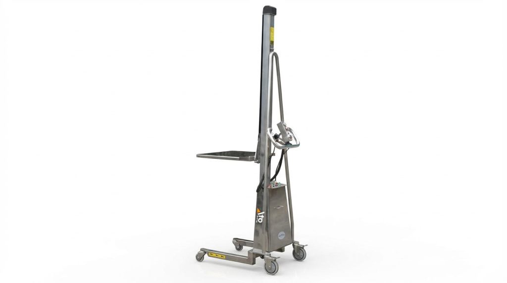
The mechanical architecture typically included a rigid base, rotating table or frame, and tilting mechanisms supported by bearings and structural members. Designers routed primary load paths from the workpiece through fixtures into the table, then through bearings and frames down to the foundation or anchors. Correct sizing of shafts, bearings, and welds based on worst-case bending moments and torsional loads limited deflection and prevented fatigue failure. Engineers minimized overhung loads and ensured anchor bolts and mounting interfaces resisted vibration-induced loosening during duty cycles. For vertical and overhead applications, anti-fall or mechanical locking devices protected against gravity-induced motion in case of drive or brake failure.
Drive, Gearbox, And Speed Control Systems
Electric work positioners used motor–gearbox assemblies to provide controlled rotation and tilt, typically via geared turntables, worm gears, or chain drives. Servo or induction motors with frequency converters provided variable speed and torque, enabling smooth low-speed positioning and stable constant-speed welding rotation. Designers selected reduction ratios so that rated motor torque exceeded required output torque with safety margins, accounting for inertia and start–stop cycles. Gearboxes required correct lubrication, backlash control, and sealing to avoid wear, noise, and oil leakage that could affect positioning accuracy. Speed control algorithms in inverters or servo drives limited acceleration and deceleration to prevent workpiece slip, while still meeting cycle-time targets.
Workholding, Center Of Gravity, And Stability
Workholding fixtures clamped components securely while transmitting loads into the positioner without slip or deformation. Engineers located the combined center of gravity of the fixture and workpiece as close as possible to the rotation and tilt axes to minimize required torque and dynamic loads. Misaligned centers of gravity created unbalanced moments, causing table wobble, increased bearing loads, and potential toppling risks for mobile or elevated units. Design calculations considered maximum rated mass, offset distance, and tilt angle to verify stability against overturning and to size counterweights if necessary. Practical setup procedures included verifying clamp integrity, checking for vibration or shake during test runs, and adjusting fixture geometry to align the center of gravity.
Integration With Robots, Cobots, And AGVs
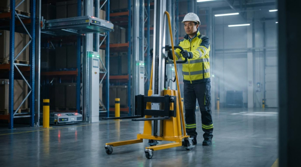
When integrated with robots or cobots, electric work positioners acted as coordinated external axes that synchronized part motion with tool paths. Communication between robot controllers and positioner drives used fieldbuses or industrial Ethernet to exchange position commands, feedback, and safety signals. Accurate kinematic models of the positioner, including axis offsets and rotation directions, were required for precise path planning and collision avoidance. In automated cells with walkie pallet truck, positioners interfaced with material handling systems to receive parts, lock positions, and confirm safe states before welding or assembly. Designers implemented interlocks, safe torque off functions, and zone monitoring so that human operators, mobile platforms, and robotic equipment could coexist without hazardous interactions.
Safety, Compliance, And Operating Best Practices

Safe operation of electric work positioners relied on disciplined procedures, compliant hardware, and trained personnel. This section focused on practical operating rules that reduced accident probability and protected equipment. It covered inspections, electrical protection, load handling, and emergency response, with examples from welding positioners, winches, and mobile elevating work platforms. The objective was to translate standards and field experience into actionable routines for shop floors and construction sites.
Pre-Use Inspection And Functional Safety Checks
Operators needed to perform structured pre-use inspections before energizing any electric work positioner. They checked rotating and tilting mechanisms for free motion, absence of jamming, and correct end-stop behavior. Fasteners at all load paths, including table mounts, anchor bolts, and fixture interfaces, required verification with visual checks and, where specified, torque control. Electrical inspections included power cords, plugs, sockets, and visible wiring, looking for cuts, abrasion, discoloration, or aging of insulation.
Functional checks validated that start, stop, and speed-control devices operated correctly and returned to safe states. For servo or frequency-converter drives, operators ran the positioner unloaded to confirm smooth acceleration, deceleration, and speed stability without abnormal noise or vibration. Limit switches, interlocks, and travel sensors needed testing by moving the axes through their safe ranges and confirming that motion stopped at predefined positions. For mobile elevating work platforms, pre-use checks also included guardrails, harness anchor points, tires or tracks, and emergency lowering systems.
Grounding, Insulation, And Electrical Protection
Grounding formed a primary barrier against electric shock in work positioners and associated equipment. Welding positioners required a dedicated protective earth connection with grounding resistance not exceeding approximately 4 Ω, measured with appropriate test instruments. Ground conductors had to be mechanically secure, corrosion-free, and sized according to applicable electrical codes. Insulation checks included visual inspection of cables, connectors, and motor terminations, as well as periodic insulation-resistance measurements; values of at least 0.5 MΩ typically indicated acceptable insulation for low-voltage systems.
Control cabinets demanded regular cleaning to remove conductive dust, spatter, and moisture that could compromise creepage distances. Protective devices such as fuses, circuit breakers, and residual-current devices needed correct ratings and documented test intervals. Operators verified that enclosure doors closed fully and that gaskets remained intact to maintain ingress protection levels. During maintenance, lockout-tagout procedures ensured that all energy sources, including electrical, hydraulic, and pneumatic, were isolated and clearly marked to prevent unintended energization.
Safe Load Handling, Speed Limits, And Work Envelopes
Safe load handling started with strict adherence to rated capacity and clearly defined work envelopes. Operators confirmed workpiece mass and center-of-gravity location before clamping, ensuring that the resultant load line passed close to the positioner’s rotation axis. Fixtures had to match the workpiece geometry and provide positive locking to prevent slip or ejection under dynamic loads. For rotating tables or tilting frames, trial runs at low speed allowed verification of stability and absence of interference with guards, cables, or surrounding structures.
Speed selection depended on workpiece mass, geometry, and process requirements such as welding or assembly. Excessive rotation or lift speed increased inertial loads, which could cause vibration, overshoot, or structural fatigue. Recommended practice used lower speeds for heavy or offset loads and limited acceleration ramps through drive parameters. For mobile elevating work platforms, operators respected manufacturer-specified travel speeds, maximum platform height under wind limits, and prohibited motions near obstacles or overhead lines. Clearly marked operating zones and barriers kept non-involved personnel outside the hazard area.
Emergency Procedures And Operator Training
Emergency preparedness required clear procedures, accessible devices, and regular drills. Operators needed to recognize abnormal conditions such as unusual noise, severe vibration, unexpected motion, or loosening of workpieces and respond by stopping the machine and isolating power immediately. Emergency stop devices had to be prominent, unobstructed, and tested during commissioning and periodic inspections. However, using emergency stops for routine halts was discouraged because it stressed components and could reduce system reliability.
Training programs covered equipment structure, control logic, limitations, and site-specific hazards. Only personnel with documented training and, where regulations required, valid operation certificates should have operated winches, positioners, or elevating platforms. Instruction included correct startup and shutdown sequences, safe parking positions, and procedures for power failures, electric leakage, or fire, including coordination with site emergency plans. Refresher training and incident reviews helped maintain competence and embed a culture of cautious, methodical operation across the workforce.
Maintenance, Troubleshooting, And Lifecycle Optimization
Maintenance of electric work positioners directly influenced uptime, positioning accuracy, and safety. Structured service routines, systematic fault diagnosis, and lifecycle planning reduced unplanned stoppages and extended asset life. This section focused on welding positioners and mobile elevating work platforms as representative electric work positioners. It linked practical inspection steps with deeper reliability strategies such as data logging and predictive maintenance.
Daily, Weekly, And Periodic Service Tasks
Daily tasks started with visual inspection and cleaning. Operators removed welding slag, spatter, dust, and oil from tables, rotating mechanisms, guide rails, and platforms. They checked cables, hoses, and air pipes for abrasion, aging, or loose joints that could compromise power or fluid supply. Functional checks included verifying start/stop, speed control, limit switches, and indicator lights before loading any workpiece.
Lubrication formed a core daily or weekly activity. Technicians applied specified lubricants to bearings, gears, chains, and linear guides according to the manufacturer’s schedule. They verified gearboxes had oil within the marked level and looked for leaks around seals and flanges. Weekly and monthly, they tightened anchor bolts, structural fasteners, and rotating-table fixings that loosened under vibration. They also tested travel limits, photoelectric sensors, and safety interlocks for repeatable operation.
Quarterly or annual tasks addressed deeper degradation mechanisms. Maintenance teams measured motor insulation resistance, targeting values at or above 0.5 MΩ and checking for overheating marks at terminals. They replaced hydraulic oil every 6–12 months, cleaned or replaced filters, and inspected hoses and valves for seepage or cracking. Control cabinets required internal cleaning, contactor and relay inspection, and verification of PLC, servo drive, and VFD wiring integrity. For long shutdowns, they cleaned equipment, applied rust inhibitors, moved axes to safe positions, isolated power and air, and used desiccants in cabinets.
Mechanical, Drive, And Control Fault Diagnosis
Mechanical faults typically manifested as jerky motion, table wobble, or abnormal noise. Jerky rotation or tilting often indicated insufficient lubrication, worn guides or bearings, or excessive gear and chain backlash. Corrective actions included cleaning and lubricating contact surfaces, adjusting gear or chain tension, and removing foreign material from motion paths. When tables wobbled or lost positioning accuracy, technicians checked anchor bolts, table mounting bolts, and shaft bearings for play and retightened or replaced components as required.
Abnormal screeching or grinding noises pointed to dry friction, damaged gears, or failing bearings. Maintenance personnel inspected gear tooth flanks for pitting, spalling, or misalignment and replaced defective parts. In the drive system, no movement or weak output suggested power loss, wiring faults, overload trips, or motor failures. Diagnostics involved confirming supply voltage, checking continuity, and examining overload relays and fuses before resetting. Irregular speed or overheating often related to incorrect VFD parameters, DC bus issues, or winding faults, which required parameter review, electrical testing, and potential motor replacement.
Control-system faults produced unresponsive commands, inaccurate positioning, or unintended starts and stops. Engineers inspected push-buttons and selector switches for oxidized contacts, loose terminals, or broken actuators. They tested sensors and encoders for correct signal levels and alignment, recalibrated PLC or drive parameters, and verified grounding and shielding to reduce electrical noise. In digital positioners, they addressed non-responsive LEDs or communications errors by checking power quality, wiring polarity, bus cable characteristics, and protocol-specific settings. Maintaining a detailed fault log with timestamps, symptoms, and remedies improved future diagnostic speed.
Hydraulic And Pneumatic Subsystem Care
Hydraulic subsystems in work positioners and elevating platforms required strict fluid management. Technicians checked reservoir levels before operation and looked for foaming, discoloration, or odor that indicated contamination or thermal stress. They replaced hydraulic oil at 6–12 month intervals using fluids conforming to standards such as ISO 11158 and ASTM D6158-05 where specified. Filters in return and pressure lines needed periodic cleaning or replacement to maintain flow and protect valves and actuators from wear particles.
Leak control was essential for safety and cleanliness. Maintenance teams inspected hoses, rigid pipes, fittings, and cylinder rod seals for sweating, drips, or damage. They replaced cracked hoses and worn seals and cleaned any leaked oil to prevent slip hazards. Pressure tests confirmed correct relief-valve settings to avoid overload of structural components. For pneumatic circuits, workers drained condensate from air tanks and filters, checked pressure regulators and lubricators, and verified that solenoid valves actuated reliably without sticking.
System performance checks focused on smooth, controlled motion under rated load. Technicians monitored lift and rotation speeds, looking for sluggish or erratic behavior that suggested internal leakage or valve malfunction. They verified that hydraulic and pneumatic components operated within specified temperature ranges to prevent seal degradation. During maintenance, they always depressurized circuits, locked out power, and followed procedures that prohibited work on energized or pressurized lines. Proper care of these subsystems reduced downtime and extended cylinder, valve, and pump life.
Digital Monitoring, Logs, And Predictive Maintenance
Digital monitoring tools allowed operators to move beyond reactive maintenance. Modern positioners integrated sensors for temperature, vibration, motor current, hydraulic pressure, and position feedback. Control systems and HMIs recorded these signals, enabling trend analysis over weeks and months. Engineers compared baseline signatures with current data to detect early changes in friction, misalignment, or electrical loading. This approach reduced unexpected failures and supported planned shutdowns for component replacement.
Event and alarm logs inside PLCs, VFDs, and servo drives provided detailed fault histories. Maintenance personnel reviewed time-stamped entries for overcurrent trips, overtemperature alarms, encoder errors, or communication losses. They correlated these records with environmental conditions and operating modes. Systematic logging of manual observations, such as unusual noise or intermittent vibration, complemented electronic data. Together, these records supported root-cause analysis and continuous reliability improvement.
Predictive maintenance strategies used analytics to estimate remaining useful life of critical components. Vibration trending on gearboxes, for example, indicated bearing wear long before catastrophic failure. Insulation-resistance trends revealed electrical aging in motors and cables. Facilities integrated these insights into computerized maintenance management systems to schedule lubrication, oil changes, and part replacements at optimal intervals. Digital tools also supported remote diagnostics, allowing specialists to review parameters and traces without on-site presence, improving response times and reducing total lifecycle cost.
Summary: Reliable, Safe, And Efficient Positioning Systems
Electric work positioners, including welding positioners and mobile elevating work platforms, relied on robust mechanical design, controlled drive systems, and well-engineered workholding to deliver accurate, repeatable positioning. Their safety and productivity depended on disciplined pre-use inspections, correct grounding and insulation, controlled speeds within defined work envelopes, and operators trained to recognize abnormal behavior and follow emergency procedures. Structured maintenance programs that combined daily cleaning and lubrication with periodic electrical, hydraulic, and pneumatic inspections extended service life, reduced unplanned downtime, and preserved positioning accuracy.
Industry practice moved toward higher integration with robots, cobots, and automated guided vehicles, which increased throughput but demanded tighter control over load paths, center-of-gravity management, and functional safety. Trend data indicated growing use of digital diagnostics, event logs, and remote monitoring to support condition-based and predictive maintenance. These tools allowed earlier detection of issues such as bearing wear, insulation degradation, hydraulic leakage, or sensor drift, reducing catastrophic failures and improving asset utilization.
Practical implementation required clear maintenance responsibilities, documented inspection checklists, and adherence to relevant electrical, mechanical, and hydraulic standards. Operators and technicians needed targeted training on fault recognition, lockout procedures, and correct use of measuring tools and test equipment. A balanced approach combined conservative mechanical sizing and safety margins with modern control hardware and analytics, avoiding over-complexity while still enabling precise, flexible positioning. Facilities that treated electric work positioners as critical production assets, rather than auxiliary tools, achieved higher reliability, safer operation, and lower lifecycle cost.