Forklift battery charging introduced unique explosion, fire, and chemical exposure hazards that required engineered controls. This article examined how lead-acid batteries generated hydrogen, how that gas behaved in charging rooms, and which OSHA thresholds defined acceptable risk. It then detailed ventilation design criteria, including airflow rates, ducting, explosion-proof fans, gas detection, and fire-zoned charging bay layouts. Finally, it covered safety systems, PPE standards, and maintenance routines that kept forklift battery rooms safe, compliant, and operationally reliable.
Battery Gas Generation And Explosion Hazards
Battery charging in forklift fleets created both chemical and electrical hazards. Lead-acid batteries generated hydrogen and oxygen, while lithium-ion packs introduced thermal runaway and toxic off‑gas risks. Poorly designed charging rooms increased the probability of explosions, fires, and accelerated battery degradation. Understanding gas generation mechanisms and dispersion behavior allowed engineers to design ventilation that stayed within regulatory limits and protected operators.
How Lead-Acid Forklift Batteries Produce Hydrogen
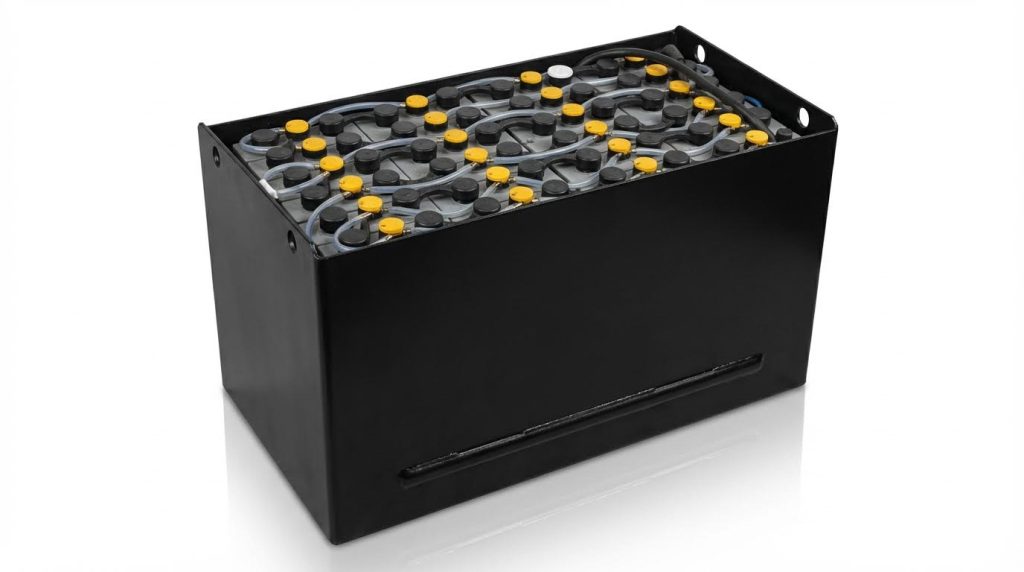
Lead-acid batteries produced hydrogen during the gassing phase of charging, typically above 80% state of charge. At this stage, charging current no longer went mainly into converting lead sulfate but instead electrolyzed water in the electrolyte. Electrolysis broke water into hydrogen at the negative plates and oxygen at the positive plates, releasing gas bubbles through vent caps. A 500 ampere-hour industrial battery could release roughly 25 liters of hydrogen during a full charge cycle, depending on charge profile and temperature.
Hydrogen generation rates increased sharply with overcharge, high equalization voltages, and elevated electrolyte temperature. Poor charger settings, sulfated plates, or imbalanced cells pushed more current into electrolysis and raised gas output. Water loss from repeated gassing required weekly top‑ups and exposed plates if neglected, which further increased internal resistance and heat. Engineers therefore specified chargers with proper voltage limits and charge curves matched to battery capacity to minimize unnecessary gassing.
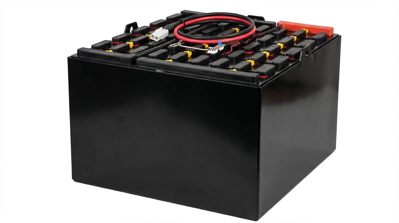
Vent caps and battery compartment openings provided only limited passive venting. When batteries sat in enclosed trays or under closed steel covers, hydrogen accumulated locally before diffusing into the room. Leaving seat hoods and battery covers open during charging significantly improved convection and reduced pocket formation. However, this practice did not replace the need for room-level mechanical ventilation sized for worst‑case gassing scenarios.
Hydrogen LEL, Risk Thresholds, And OSHA Requirements
Hydrogen had a lower explosive limit of about 4% by volume in air. At or above this concentration, a small ignition source such as a relay contact or static discharge could trigger an explosion. Industry practice kept design concentrations below 25% of the LEL, or roughly 1% hydrogen, to maintain a conservative safety margin. For a 10 cubic meter room, 4% hydrogen corresponded to about 400 liters of gas, so a single 500 ampere-hour battery releasing 25 liters could meaningfully raise concentration in a stagnant space.
OSHA 1910.178 and 1910.441 required adequate ventilation in battery charging areas to prevent accumulation of explosive gas mixtures. The standards prohibited open flames, sparks, or electric arcs in charging zones and required equipment that did not introduce ignition sources. Facilities had to design airflow so that hydrogen and oxygen diffused safely and did not exceed hazardous concentrations during peak charging periods. Compliance involved both engineering controls and administrative controls such as no‑smoking policies and restricted tool use.
To maintain hydrogen levels well below 4%, guidance recommended 5–10 air changes per hour in typical charging rooms, with higher rates where multiple large batteries charged simultaneously. Some design methods specified minimum airflow of approximately 0.3 cubic meters per minute per kilowatt of charger power. Gas detection systems with sensors set to alarm at about 1% hydrogen provided an additional safety layer and early warning of ventilation failures. OSHA also required designated charging areas with clear signage and procedures to control worker exposure.
Gas Behavior In Charging Rooms And Confined Spaces
Hydrogen was the lightest gas and rose rapidly toward ceilings and overhead voids. In charging rooms with poor vertical mixing, hydrogen formed stratified layers near roof decks, beams, and cable trays while air near the floor remained relatively unaffected. This stratification created hidden pockets near lights, conduit, and overhead electrical equipment, where even minor faults could ignite an explosive mixture. Smooth ceiling surfaces and well‑placed exhaust grilles reduced dead zones where gas could stagnate.
Confined or partially enclosed spaces such as battery compartments, alcoves, or low headroom mezzanines presented higher risk. When forklifts charged with seat hoods closed, hydrogen accumulated first under the cover, then leaked into the surrounding area. Narrow rooms with inadequate cross‑ventilation reached hazardous concentrations faster than large, open bays. Charging inside containers, trailers, or small maintenance closets significantly increased the probability of reaching or exceeding the LEL.
Effective ventilation design accounted for hydrogen’s buoyancy by placing exhaust points high and ensuring sufficient makeup air at lower elevations. Mechanical systems with explosion-proof fans captured rising gas and discharged it safely outdoors, away from intakes or ignition sources. Computationally simple checks, such as verifying 5–10 air changes per hour and validating actual airflow paths with smoke tests, helped confirm that theoretical designs worked in practice. In mixed-chemistry rooms that also housed semi electric order picker or walkie pallet truck, engineers typically prioritized overhead venting and segregated zones to control both hydrogen accumulation and hot plume movement during a failure event. Additionally, equipment like the manual pallet jack required careful placement to avoid obstructing airflow.
Ventilation Design Criteria For Charging Areas
Ventilation design for forklift battery charging areas must control hydrogen concentration well below the lower explosive limit and manage heat from both lead-acid and lithium-ion chemistries. Engineers typically targeted 5–10 air changes per hour as a minimum, with higher values for dense lead-acid installations. Design calculations used both air-change methods and power-based formulas to size fans and ducts. Systems also integrated gas detection, zoning, and fire protection to comply with OSHA and electrical safety standards.
Airflow Rates, Air Changes, And CFM Sizing Methods
Engineers sized ventilation using two complementary approaches: air changes per hour and airflow per unit charging power. For lead-acid charging rooms, guidance recommended 12–15 air changes per hour, while 6–8 air changes per hour often sufficed for lithium-ion focused rooms. Another method used a minimum airflow of 0.3 cubic metres per minute per kilowatt of connected charger load to dilute hydrogen and other gases. For a 10 kilowatt charging station, this translated to roughly 300 cubic feet per minute of continuous ventilation. Designers also validated that hydrogen stayed below 1% of the lower explosive limit, which corresponded to about 1% absolute hydrogen concentration, using worst-case gas evolution rates such as 25 litres of hydrogen from a 500 ampere-hour battery charge.
Exhaust, Ducting, And Explosion-Proof Fan Selection
Exhaust systems removed hydrogen at ceiling level and supplied replacement air without creating stagnant pockets. Designers used ducted exhaust with fans rated for hazardous locations, typically classified as Class I Division 2, to avoid ignition from motor sparks. For lead-acid rooms, explosion-proof fans and non-sparking impellers were standard because hydrogen could reach flammable levels near ceilings or poorly vented corners. Engineers sized ducts to limit friction losses and avoid high velocities that created noise or erosion; upgrades from 200 millimetre to 250 millimetre ducts often eliminated hotspots by reducing pressure drop. Intake and exhaust placement followed gas buoyancy: intakes introduced make-up air at lower levels, while exhaust grilles near the ceiling captured rising hydrogen plumes. Systems handling lithium-ion charging prioritized heat removal, so layouts sometimes combined overhead exhaust with distributed supply diffusers to keep cell temperatures below about 30 degrees Celsius.
Gas Detection, Sensor Placement, And Calibration
Hydrogen detection formed a second safety layer when ventilation performance degraded or abnormal charging occurred. Facilities typically installed fixed hydrogen sensors set to alarm at around 1% hydrogen concentration, well below the 4% lower explosive limit. Engineers mounted hydrogen sensors near ceilings or in the highest points of the room, because hydrogen was lighter than air and accumulated overhead. Lithium-ion areas instead relied on carbon monoxide and temperature sensors, since early thermal runaway produced hot gases rather than large hydrogen volumes. Detection systems interfaced with building management controls to boost fan speed, trigger alarms, and, in some cases, shut down chargers automatically when gas levels exceeded thresholds. Maintenance programs included gas sensor calibration at least every six months, because field data showed that roughly one quarter of detection failures resulted from sensor drift or fouling. Annual airflow verification, often using smoke pencils, confirmed that sensor coverage matched actual flow patterns.
Layout Of Charging Bays, Clearances, And Fire Zoning
Charging bay layout influenced ventilation effectiveness, fire safety, and traffic flow. Designers arranged chargers in linear or back-to-back rows with clear aisles and at least 4 metre turning radii for forklifts, reducing collision risks and preventing damage to ventilation or electrical equipment. Fire zoning strategies separated lead-acid and lithium-ion areas with rated firewalls and non-overlapping exhaust zones to avoid cross-contamination of gases and heat. Codes and best practice recommended 1 metre clearance between lithium-ion battery racks for cooling airflow and maintenance access, and approximately 48 inches of working clearance in front of electrical panels and chargers for arc-flash protection. Floors near charging bays used acid-resistant epoxy coatings and a slight 1–2 degree slope toward drains to manage electrolyte spills without pooling. Designers also reserved overhead space above battery racks for unobstructed venting, avoiding low ceilings or suspended storage that could trap hydrogen and defeat otherwise adequate airflow calculations.
Safety Systems, PPE, And Maintenance Practices
Safety systems around forklift battery charging areas protected workers and assets when correctly engineered. This section connected regulatory eyewash and spill-control requirements with PPE selection, electrical protection, and maintenance routines. Integrating these elements into a single operating procedure minimized hydrogen explosion risk, acid exposure, and thermal or electrical failures. The goal was a charging zone that stayed compliant, predictable, and resilient under fault conditions.
OSHA-Compliant Eyewash, Showers, And Spill Control
OSHA 1926.441(a)(6) required quick drenching facilities within 7.6 m of battery handling areas. Emergency eyewash stations had to deliver at least 0.4 gallons per minute for 15 minutes to ensure full decontamination after electrolyte splashes. Portable eyewash bottles only served as interim devices while an affected worker moved to a plumbed or self-contained station. Facilities handling larger fleets typically installed combined drench showers and eyewash units near lead-acid charging racks.
Spill control engineering started with flooring and drainage design. Charging bays used chemically resistant, non-porous finishes such as thick epoxy over concrete, often sloped 1–2° toward collection drains to contain acid spills. Soda ash or similar alkaline neutralizing agents needed to be staged within arm’s reach of charging stands, alongside non-sparking scoops and absorbent pads. Operators had to document spill response procedures, including neutralization, solidification, and disposal in accordance with local environmental regulations.
Water supply capacity also influenced layout. A reliable water source close to the charging area supported both emergency drenching and routine cleanup after minor electrolyte splashes. Facilities sometimes installed dedicated rinse points and hose bibs that did not compromise electrical clearances or create slip hazards. Clear signage identified eyewash, showers, and spill kits so operators could locate them in seconds during an incident.
PPE Standards For Lead-Acid And Lithium-Ion Batteries
PPE requirements differed by chemistry because hazards differed. Lead-acid battery handling exposed workers to 10% sulfuric acid and hydrogen gas, so OSHA guidance referenced chemical-resistant gloves, aprons, and full-face protection. Typical specifications included 6 mm neoprene or equivalent acid-resistant gloves, polycarbonate face shields rated for acid splash, and goggles underneath for secondary containment. Steel-toe safety footwear protected against crush injuries from heavy industrial batteries.
Lithium-ion systems introduced higher nominal voltages and arc-flash potential rather than liquid acid hazards. For these, dielectric gloves rated at least 500 V provided insulation during connection and disconnection tasks. Operators also used arc-rated face shields or goggles compliant with relevant electrical safety standards, matched to the prospective incident energy level. Flame-resistant clothing reduced injury from possible thermal runaway events or arc flashes during faults.
Facilities with mixed chemistries had to define PPE zones and task-based requirements to avoid under-protection. For example, a worker topping up lead-acid electrolyte required chemical splash PPE, while another troubleshooting a lithium-ion battery management system needed electrical PPE. Training programs clarified donning and doffing procedures, inspection of gloves and shields for degradation, and replacement intervals based on actual exposure rather than calendar time alone.
Electrical Safety, GFCI, And Non-Sparking Equipment
Electrical infrastructure around charging bays had to limit shock, arc, and ignition risks. Ground-fault circuit interrupters protected personnel from leakage currents, with breakers commonly specified at 30 mA trip sensitivity. Ground-fault monitors limited permissible leakage voltages to approximately 50 V, aligning with electrical safety guidelines for wet or conductive environments. Charging circuits were typically routed through IP65 or better enclosures to keep out conductive dust and moisture.
Layout standards required clear working space around live equipment. A 1.2 m clearance envelope around chargers and disconnects allowed safe operation and arc-flash egress. Disconnect switches needed visible, durable labels so technicians could isolate circuits quickly during emergencies, reducing response times measured in tens of seconds. Where hydrogen concentrations could approach regulatory thresholds, outlets and fixtures had to be non-sparking and suitable for classified locations, such as NEMA 4X housings in appropriately rated zones.
Non-sparking hand tools reduced ignition risk when workers serviced battery terminals or racks. Copper-beryllium or aluminum-bronze tools minimized spark energy compared with standard steel tools. Operators removed metallic jewelry and avoided loose conductive objects near uncovered battery tops to prevent accidental bridging between terminals. These practices complemented ventilation and gas detection, forming layered protection against ignition inside charging rooms.
Inspection, Torque, And Predictive Maintenance Routines
Structured inspection and maintenance routines directly influenced battery reliability and safety. Lead-acid batteries required weekly checks of electrolyte levels, with top-ups using deionized water only. Monthly cleaning of terminals with a baking soda and water solution controlled corrosion, which otherwise increased contact resistance. Lithium-ion systems did not need watering, but their battery management systems required firmware reviews and updates roughly twice per year to maintain proper protection logic.
Mechanical connections demanded particular attention. Loose terminals increased resistance dramatically, converting electrical power into localized heat that degraded lugs and insulation. A typical industrial practice torqued terminals to 10–12 N·m using calibrated tools and verified them quarterly. Maintenance logs recorded torque values, rework, and component replacements, enabling traceability after any overheating incident or near-miss.
Predictive maintenance used thermal imaging and sensor data to flag emerging issues before failures occurred. Infrared cameras scanned strings during or immediately after charging, highlighting hot spots that indicated poor connections or internal cell problems. Gas and temperature sensors required calibration about every six months, because drift in detection thresholds caused roughly one quarter of field failures. Combined inspection, torque verification, and sensor maintenance reduced unplanned outages and extended battery service life while keeping hydrogen and thermal hazards under tight control.
Summary: Safe, Compliant Forklift Battery Ventilation
Safe forklift battery charging required a systems approach that combined gas physics, ventilation engineering, and OSHA compliance. Lead-acid batteries generated hydrogen as they approached full charge, with explosion risk increasing sharply above 4% concentration, the approximate lower explosive limit. Effective designs kept hydrogen well below 1% of the LEL by using correctly sized airflow, typically 5–15 air changes per hour or at least 0.3 m³/min per kilowatt of charging power. Lithium-ion systems reduced hydrogen hazards but still demanded ventilation to manage heat and toxic off-gassing during failures.
Industry practice converged on mechanically ventilated charging rooms with explosion-proof fans for lead-acid installations and well-cooled, monitored spaces for lithium-ion banks. Engineers positioned supply and exhaust to sweep the full room volume, avoided stagnant ceiling pockets, and used ducted exhaust for Class I Division 2 classified zones. Gas detection systems, typically hydrogen sensors for lead-acid and temperature or carbon monoxide sensors for lithium-ion, integrated with alarms and sometimes fan-speed control. Facilities also implemented clear bay layouts, 1-meter or greater separations, and fire-rated separations between chemistries to limit incident propagation.
Practical implementation required more than hardware. Facilities installed OSHA-compliant eyewash and shower stations, spill-neutralization kits, non-sparking electrical equipment, and clearly marked emergency disconnects. Operators trained on leaving battery covers open during charge, enforcing no-smoking rules, and using appropriate PPE reduced incident frequency significantly. Predictive maintenance, including terminal torque checks, thermal imaging, and sensor calibration, improved reliability and lowered lifecycle costs. Overall, technology trends favored smarter chargers, integrated monitoring, and better ventilation controls, but did not remove the need for conservative design margins and disciplined operational practices.