
A well‑engineered scissor lift mechanism converts compact input force into safe, stable vertical motion. This article walks through how the crossed arms, pins, and hydraulic cylinder work together, how loads and stresses flow through the structure, and how modern control and optimization keep platforms efficient and reliable. You will see how geometry, force transmission, and safety factors shape real‑world capacities and duty cycles, so you can specify or design a lift with confidence. The focus is practical: linking core physics to everyday decisions on height, load, stability, and maintenance.
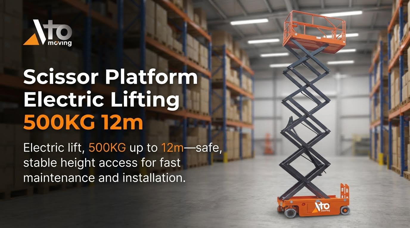
Core Geometry And Working Principle Of Scissor Lifts

Main structural elements and kinematic layout
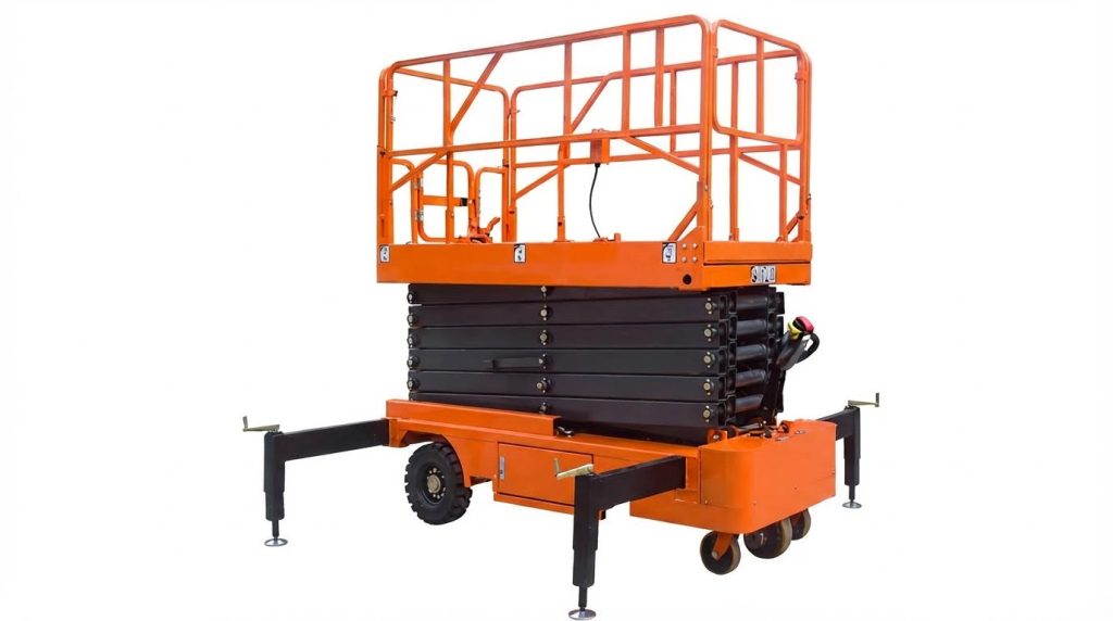
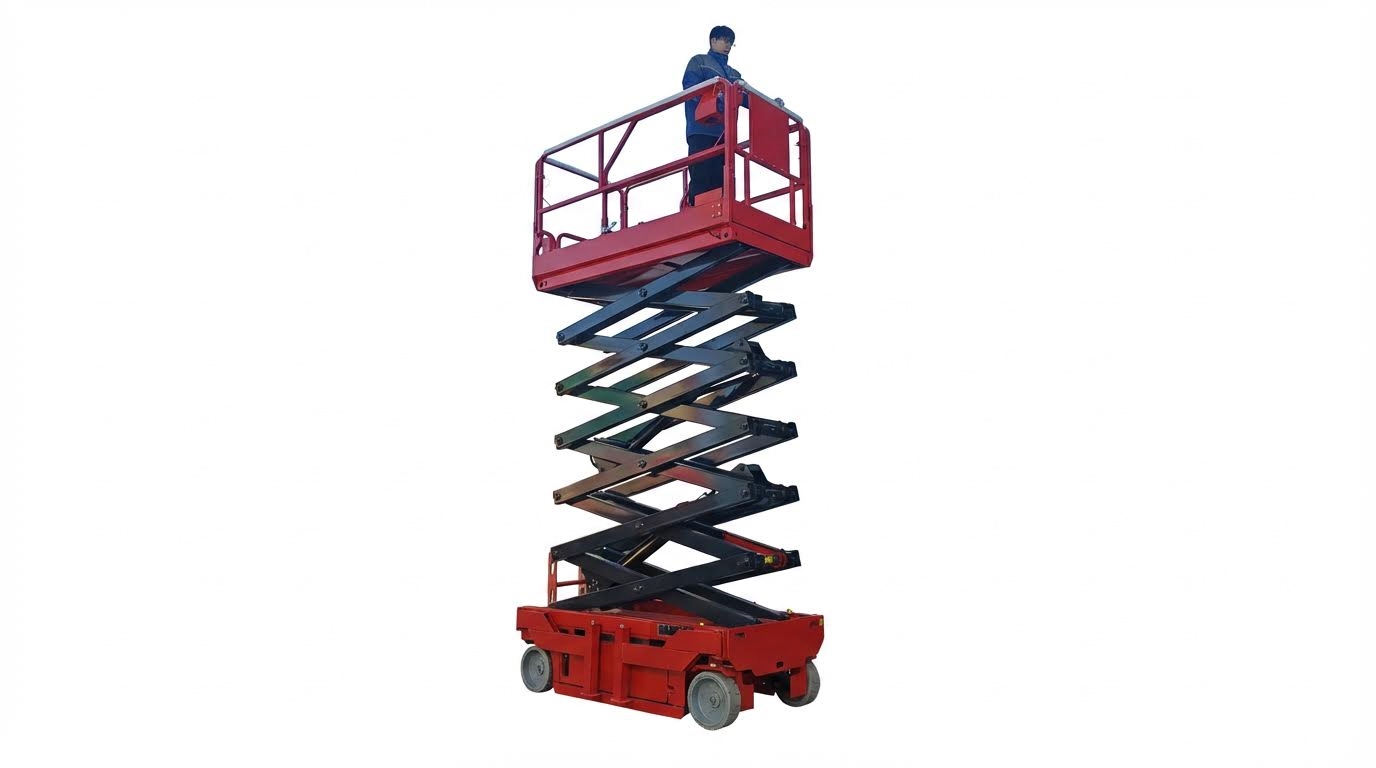
A typical scissor lift mechanism uses multiple pairs of crossed arms arranged as repeating “X” linkages between a rigid base and the elevated platform. Each pair of arms connects with pins at the center and at the ends, forming a planar linkage that can fold flat or extend vertically while keeping the platform approximately level. At least one actuator, most often a hydraulic cylinder, applies force between the base and one arm or linkage point to open the “X” pattern and raise the platform. The base guides may be fixed, rolling, or pinned, which changes how horizontal reactions develop and how the structure carries load. The overall vertical travel comes from the cumulative extension of all the stacked scissors, so adding more stages increases working height without changing the basic footprint. The layout must keep the platform’s center of gravity within the base support polygon to maintain stability under rated load.
- Upper structure: platform, guardrails, and load interface.
- Middle structure: scissor arms, central and end pivots, and any intermediate tie members. Typical fixed scissor lifts use crossed bars forming an “X” between base and platform.
- Lower structure: base frame, rollers or fixed supports, and cylinder mount points.
The kinematics are governed by arm length, pivot spacing, and the angle of the arms relative to the base. As the actuator extends, it changes this angle, which converts horizontal or diagonal actuator motion into vertical lift of the platform. Careful geometric design ensures smooth motion, acceptable side-shift of the platform, and clearance between members over the full stroke.
Mechanical advantage and force transmission
The scissor platform mechanism works as a variable mechanical advantage system: at low platform height, small actuator strokes create large platform movement but require high force; at greater height, the opposite occurs. The mechanical advantage depends on the arm length L, the angle θ between the arm and the horizontal, and the horizontal distance d from the base pivot to the actuator attachment point. These parameters define the relationship between actuator thrust and vertical lifting force on the platform. At small θ (nearly closed lift), the geometry produces the maximum cylinder force demand and the lowest efficiency, which is why designers size the cylinder and pins for this worst case. As θ increases and the lift rises, the required cylinder force decreases and mechanical advantage improves for a given load. Engineers must also ensure that the transmitted forces do not exceed the yield or buckling limits of arms and pins, with checks on bending, shear, and bearing in all critical joints. Maximum load capacity depends on arm material strength, pivot locations, arm angles, and actuator force capacity. In multi-stage layouts, each additional scissor pair shares and redirects the load, so local forces at some hinges can be several times the platform load. Designers therefore select profiles and pins with adequate stiffness and apply safety factors typically between 1.5 and 3 on calculated stresses to keep operation within the elastic range under all rated conditions..
Engineering The Mechanism: Strength, Hydraulics, And Control
Load paths, stresses, and safety factors
In any scissor platform mechanism, the primary load path runs from the platform, through the scissor arms and pins, into the base and actuator. The maximum load capacity depends on arm and pin material strength, geometric layout (arm length, pivot spacing, angles), actuator force, and boundary conditions such as fixed or roller-supported ends key design factors. Engineers check static equilibrium of the linkage to determine internal forces in each arm and at each joint, then verify that these forces stay below yield and buckling limits for all components strength of components.
- Arms are checked for combined bending and compression, using section properties (E, I, effective length) to avoid column buckling.
- Pins and joints are checked in shear and bearing, with higher-strength steels often used for pins to increase margin.
- Stress hot-spots typically occur near upper scissor junctions and actuator attachment points, where bending and axial loads combine.
Finite element analysis helps refine these checks by showing stress distribution and deformation under rated loads. One studied scissor platform lift designed for 500 kg at 2 m height showed maximum von Mises stress of about 56.9 MPa at the upper scissor connections and a maximum deflection of about 0.69 mm at full load, with minimal deformation in the lower arms FEA stress and deformation results. Safety factors are then derived from these peak stresses; values above 3 are typical for lifting systems, and one analysis reported minimum safety factors of about 4.3 for arms and 6.2 for pins, well above the commonly recommended range of 1.5–3 for structural components recommended safety factor range example safety factor values.
Typical checks in load-path design
For a robust scissor lift mechanism, engineers systematically verify: axial compression and buckling of each arm segment, bending stresses at mid-spans, shear and bearing at all pins, local plate stresses at actuator clevises, and base-frame reactions into the floor or chassis.
Hydraulic cylinder sizing and circuit design
Hydraulic cylinder sizing starts from the worst-case mechanical disadvantage in the scissor lift mechanism, usually at the initial lift when the arms are near-horizontal. At that stage, the required piston force can be several times the rated platform load; one kinematic study reported a peak piston force of about 44,700 N at initial opening, with an optimal cylinder angle of about 16.8° to balance force and package height piston force and angle optimization. Cylinder bore is then selected so that required thrust stays below allowable pressure, with a margin for dynamic effects and pressure spikes.
A documented scissor lift used a double-acting cylinder with 70 mm bore and 400 mm stroke, driven at about 116 bar, and required roughly 1.26 kW hydraulic power, leading to a 1.5 kW motor selection example cylinder and power sizing. The hydraulic circuit typically includes:
- Pressure unit and filters to provide clean, stable supply.
- Directional control valve (often 4/3) for extend, hold, and retract modes.
- Flow control valves to regulate lift speed and prevent sudden movements.
- Safety devices such as pressure relief valves and, in some designs, accumulators to maintain function during transient pressure loss hydraulic circuit components.
Where one cylinder drives multiple scissor stages, engineers use specific thrust formulas for one-, two-, or three-set configurations to size the actuator and main hinges correctly multi-set scissor configurations. Control-wise, modern circuits may integrate proportional or flow-control elements to smooth motion and avoid pressure spikes that could overload the structure or reduce service life hydraulic integration and control.
| Design parameter | Typical consideration |
|---|---|
| Cylinder bore | Must provide required thrust at available system pressure with safety margin. |
| Stroke | Matches vertical travel and linkage geometry, with allowance for end cushions. |
| Flow rate | Sets lift speed; limited by comfort, stability, and power availability. |
| Circuit safety | Relief valves, check valves, and accumulators to prevent uncontrolled descent. |
Simulation, optimization, and emerging technologies
Simulation is now central to scissor lift mechanism design. Engineers build kinematic and dynamic models to map cylinder force versus lift height and to identify the most demanding operating points, such as start-up or emergency lowering. One optimization study used such models to tune cylinder placement and reported that adjusting arm and plate thicknesses cut structural weight by about 290 kg while keeping maximum stress below 230 MPa weight optimization results.
Finite element analysis complements these kinematic models by validating arm profiles, pin diameters, and weld details against real load cases. For example, hollow rectangular arms of 80×40×5 mm in St37 steel and Ø40 mm pins in higher-strength steel were verified to carry 500 kg with low stress and deflection, and with safety factors above 4 for arms and 6 for pins material and safety factor data. Such validated models allow designers to trim unnecessary material, improving energy efficiency and payload-to-weight ratio.
Emerging trends focus on smarter control and better materials. Advanced steels and targeted heat treatment at high-wear pivot and contact zones increase fatigue life without adding much mass material selection and heat treatment. On the control side, integrated sensors and electronic valves enable smoother motion profiles, automatic overload detection, and condition monitoring of the scissor lift mechanism, which in turn supports predictive maintenance and higher uptime.
Applying The Design: Capacity, Duty Cycle, And Specification
Matching platform height, load, and duty requirements
Translating a scissor lift mechanism from concept to specification starts with three coupled choices: platform height, rated load, and duty cycle. The geometry of the scissor arms, pivot locations, and actuator position sets the achievable stroke and the force required at each height. The maximum load is limited by arm and pin strength, actuator thrust, and boundary conditions at the base and platform, such as fixed or rolling ends. These factors must stay within allowable stress and deflection limits with an adequate safety factor. Key design limits include material strength, arm length, pivot spacing, and actuator capacity.
For a given required platform height, the number of scissor stages and arm length are selected to achieve stroke while maintaining acceptable arm angles at full extension. At small arm angles, mechanical advantage is low and the cylinder force peaks, so engineers check the worst‑case load at initial lift. Kinematic studies showed that the maximum piston force occurred at the first opening phase, with an optimal cylinder angle around 16.8° to balance force and package height. This type of simulation helps position the cylinder and hinges for efficient force transmission.
Duty cycle defines how often and how long the lift runs at or near rated load. Light‑duty maintenance access may involve a few cycles per day, while production handling can run many cycles per hour. Higher duty cycles drive larger hydraulic power units, more robust cooling, and stricter limits on stress range to control fatigue. In one 500 kg, 2 m lift example, finite element analysis found maximum von‑Mises stress around 56.9 MPa at upper scissor connections and peak deformation under 0.7 mm, with minimum safety factors above 4 on arms and above 6 on pins, exceeding typical minimums of 1.5–3 for lifting structures. These results demonstrate how geometry, material choice, and load level combine to meet safety and stiffness targets.
To specify a scissor lift mechanism correctly, engineers usually work through:
- Define maximum platform height, outreach constraints, and closed height envelope.
- Set rated load including people, tools, and dynamic allowances.
- Classify duty cycle (cycles per hour, hours per day, lifetime cycles).
- Select arm configuration and cylinder layout to satisfy height and force limits.
- Verify stresses, deflections, and fatigue with hand checks and finite element models.
Stability, standards, and lifecycle maintenance
Even a well‑sized scissor lift mechanism can fail in service if stability, standards, and maintenance are neglected. Stability depends on base dimensions, wheel or support layout, center‑of‑gravity position, and stiffness of the scissor structure. Designers ensure that the combined center of gravity of lift plus load remains within the support polygon under worst‑case conditions, such as maximum height, rated load, and allowable platform offset. Proper arm sizing, pin stiffness, and control of clearances limit sway and tilting. Load‑path checks confirm that arms, pins, and actuators all remain below yield and buckling limits with the chosen safety factor.
Hydraulic and control design also support safe performance over the full life. Double‑acting cylinders, pressure‑rated hoses, and valves are selected so that system pressure at maximum load stays within the rated limit with margin. A typical circuit may include a pressure unit, filters, sequencing valves, directional control valves, flow control, and an accumulator to manage controlled motion and pressure loss events. Such circuits have been used to drive cylinders of around 70 mm bore at pressures on the order of 100–120 bar with motor powers near 1–2 kW for mid‑size lifts.
Lifecycle maintenance planning starts at the design stage. Wear points at pivots, rollers, and sliding interfaces require access for inspection and lubrication. Regular inspections focus on hydraulic leaks, structural cracks, pin wear, and loose connections to prevent progressive damage. Routine tasks include checking hoses and fittings, replacing worn components, and lubricating scissor platform arms and pivot points on defined intervals.
Operational safety procedures complement the mechanical design. Pre‑operation checks verify guardrails, emergency stops, brakes, and controls, while site assessments confirm level, firm ground and clearance from overhead hazards. Operators are trained not to exceed rated load, to maintain position within guardrails, and to avoid sudden movements that could compromise stability. Standard practice includes pre‑use inspections, safe positioning, and controlled operation and compliance with guardrail, fall protection, and stabilization requirements. When these design, specification, and maintenance elements align, the scissor lift delivers safe, predictable performance across its intended service life.
“”
Key Takeaways For Selecting And Designing Scissor Lifts
Scissor lift performance rests on one foundation: geometry, forces, and controls must work together with margin. Arm lengths, pivot spacing, and cylinder placement set the motion and the worst loading points, so engineers must size the structure for the initial lift phase, not just steady operation. Strength checks on arms, pins, and base frame keep stresses well below yield and buckling, while hydraulic sizing ensures the cylinder can deliver peak thrust at realistic system pressure.
Simulation and finite element analysis turn these checks into a reliable design. They highlight stress hot‑spots, guide material thickness, and help reduce dead weight without cutting safety factor. Stability and standards then shape the base footprint, center‑of‑gravity limits, and control strategy, so the lift stays upright and predictable at full height and rated load.
For operations and engineering teams, the best practice is clear. Start from required height, load, and duty cycle. Choose a scissor layout and hydraulic package that meets those needs with proven safety factors and validated analysis. Build in access for inspection and lubrication, and enforce structured maintenance and operator training. When you follow this path, a scissor lift from Atomoving can deliver safe, repeatable service over its full life.
Frequently Asked Questions
How does a scissor lift mechanism work?
A scissor lift operates using a hydraulic or pneumatic system. When activated, the system pushes fluid or air into cylinders, causing them to extend outward. This movement forces the criss-crossed supports, known as the scissor legs, to push apart and lift the platform vertically. To lower the lift, the system releases the pressure, allowing the fluid or air to return to the reservoir and the platform to descend under gravity. Scissor Lift Guide.
What is the purpose of the scissor mechanism in lifts?
The scissor mechanism is designed to provide stable vertical movement. It uses linked, folding supports arranged in a criss-cross ‘X’ pattern. This design allows the lift to achieve significant height while maintaining balance and load-bearing capacity. The mechanism is widely used in Material Handling Equipment for tasks like warehouse stacking, maintenance work, and inventory management. Scissors Mechanism Overview.

