If you are asking “why won’t my aerial platform lift,” the answer almost always sits in the electrical or hydraulic systems. This guide walks you through how dual control stations, safety interlocks, wiring, and hydraulics interact so you can diagnose no-lift and slow-lift problems logically instead of guessing. You will see practical checks for power, harnesses, valves, pressure, and leaks, plus how safety devices can intentionally block lift when something is wrong. Use it as a structured, step-by-step approach to get the platform moving again without compromising safety.
Understanding No-Lift Symptoms And Safety Interlocks
When operators ask “why won’t my aerial platform lift,” the answer is often hidden in how the safety circuits are designed to say “no.” This section explains how the dual control stations share authority and how limit switches, tilt sensors, and overload devices intentionally block lift when conditions are unsafe. Understanding these interlocks helps you separate real faults from normal safety behavior and avoid bypassing critical protections.
How dual control stations share lift authority
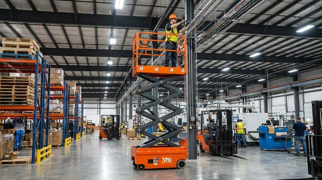
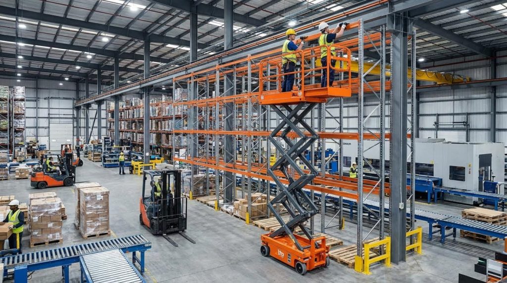
Most aerial lifts use a dual-control architecture with a base station and a platform (basket) station tied together through a main wiring harness. Both stations feed commands into safety relays and interlocks that decide whether the lift function is enabled. When this logic chain is open anywhere, the machine will not raise even though power may be present. Typical systems route basket and base commands through relays, limit switches, and safety interlocks near the hydraulic manifold.
- Basket control panel usually has joysticks, function switches, and an emergency stop.
- Base control panel provides backup control and an emergency override for rescue.
- A main wiring harness carries all command and feedback signals between the two.
- Safety relays decide which station has authority and whether lift is permitted.
- Open emergency stop, faulty selector, or broken harness wire will block lift.
Typical “no-lift” questions to ask around dual controls
Technicians should quickly confirm: which station is selected, whether both emergency stops are reset, and if any fault lamps or alarms are active. Many “why won’t my aerial platform lift” complaints come from a simple mis-set selector or an emergency stop mushroom that looks out but is still latched.
| Item | Basket (Platform) Station | Base (Ground) Station | Impact on No-Lift Symptoms |
|---|---|---|---|
| Primary purpose | Normal operation at height | Backup / ground control | Base can often move lift when basket controls fail |
| Emergency stop | Mushroom button in platform panel | Mushroom button at chassis | Either E-stop open will disable all lift functions |
| Control selector | Panel-mounted or key switch | Panel-mounted or key switch | Wrong position can leave both stations disabled |
| Signal path | Short harness to junction, then main harness | Direct to relays / ECU and hydraulic manifold | Damage in main harness can block both stations |
| Typical failures | Worn joystick, stuck E-stop, water in switches | Corroded switches, damaged wiring at frame | Machine appears dead even though power is available |
The dual-control logic also interacts with hydraulic solenoids. Lift commands from either station energize solenoids in a relay bank near the hydraulic manifold, but only if safety interlocks are closed. Technicians typically test each solenoid for resistance and actuation when tracing no-lift faults. If the solenoid never sees voltage, the problem is usually in the control or safety chain, not the hydraulics.
- Verify base/basket selector position before deeper diagnostics.
- Check that both emergency stops are pulled out and latched.
- Inspect the main harness near pivots and hydraulic lines for abrasion or rodent damage. These areas are common failure points from movement, oil, and corrosion.
- Use continuity testing with a multimeter if visual inspection does not show the fault.
Role of limit switches, tilt sensors, and overload devices
Modern aerial lifts rely on multiple safety devices that intentionally stop lifting when the machine is out of its safe envelope. These devices answer the operator’s “why won’t my scissor platform lift” question with hard electrical facts: a contact is open, so the circuit says no. Key devices include limit switches, tilt sensors, and overload protection circuits.
| Safety Device | What it Monitors | How it Blocks Lift | Typical No-Lift Symptom |
|---|---|---|---|
| Limit switches | Boom angle, extension, stowed position, outriggers | Open contact in lift-enable circuit when unsafe position is detected | Lift works only in certain positions or not at all until fully stowed |
| Tilt sensors | Chassis inclination (side-to-side / front-to-back) | Interrupts platform functions when tilt exceeds set limit | Lift and drive disabled on uneven ground; alarm may sound |
| Overload devices | Platform load or structural stress | Opens overload relay or sends fault to controller | Machine will not raise or only lowers until load is reduced |
| Emergency stop switches | Operator emergency input | Cuts power to control and solenoid circuits | No functions from either station until reset |
| Other safety interlocks | Guardrails, gates, manual descent, etc. | Open-circuit when gates open or descent handle pulled | Random no-lift complaints after access or service work |
Many pre-operational checklists require regular testing of these devices. Tilt sensors, overload alarms, and emergency stop switches should be verified for proper operation during routine inspections. A sensor that never trips is just as dangerous as one that trips too easily.
- Limit switches around booms and scissor stacks ensure the structure is in a safe zone before lift is allowed.
- Tilt sensors prevent raising the platform on excessive slopes, which could cause tip-over.
- Overload devices stop lift when platform capacity is exceeded, forcing the operator to remove weight.
- Hydraulic interlocks may also monitor pressure and valve position to detect abnormal conditions.
Field tips for diagnosing safety-device related no-lift
1. Observe indicators: Look for tilt or overload lights and listen for alarms before assuming an electrical fault.
2. Check the ground: Reposition the machine on level ground and re-test lift. If it now works, the tilt sensor likely did its job.
3. Reduce load: Remove tools and materials from the platform until you are sure you are below rated capacity.
4. Inspect switches: Confirm mechanical actuators on limit switches move freely and are not bent or contaminated.
5. Test continuity: With power off, use a multimeter to verify that each safety device closes and opens as you move it through its travel.
Hydraulic behavior often reflects these safety decisions. If the safety circuit is open, lift solenoids never energize, so the platform will not raise even though hydraulic fluid level and pump condition are acceptable. This is why technicians always confirm the safety interlock chain before chasing hydraulic “ghosts.”
- Start with visible safety devices: gates, rails, limit-switch actuators, and manual descent handles.
- Use the operator’s manual to locate all tilt and overload sensors if they are not obvious.
- Document any intermittent behavior in a maintenance log; many issues are position- or load-dependent.
Diagnosing Electrical Failures In Aerial Lift Circuits
When operators ask “why won’t my aerial platform lift,” electrical faults are one of the first places to look. The dual control architecture, long wiring runs, and multiple safety interlocks mean a single bad connection can stop all lift functions. This section focuses on fast, structured checks you can do with basic tools before assuming a major component has failed.
Basket and base control panel checks
Start at the controls, because every lift command originates here. Both the platform (basket) and base panels must be healthy, correctly selected, and free of stuck or open safety switches for the lift circuit to energize. A single emergency stop left pushed in can mimic a major failure.
- Confirm power availability first (battery charged, main disconnect on, key switch in correct position).
- Check that only one control station is selected if the machine uses a selector switch for base vs basket.
- Verify all emergency stop buttons on basket and base panels pull out and latch correctly.
- Cycle the lift enable / deadman foot switch and joystick enable triggers while observing status lamps or display, if equipped.
- Inspect the basket control panel for moisture, physical damage, or contamination that could short low-voltage circuits. Faulty or wet control panels often cause unresponsive or erratic lift commands.
- Check that all function switches and joysticks return to neutral and are not mechanically jammed.
Quick functional test sequence
1. Turn key to base controls, release all emergency stops, and attempt to raise using base lift switch. 2. If base works but basket does not, fault is likely in basket panel, basket wiring, or selector logic. 3. If neither station works, suspect main power, safety interlock chain, or common wiring/relays.
Control panels are common failure points when operators report that the machine will drive but not lift. If drive functions work, focus on the specific lift command path and any separate “lift enable” circuits that feed it. Keeping panels clean and dry, and performing regular functional checks, greatly reduces unexplained no-lift complaints. Routine inspection and cleaning of control panels were recommended as a preventive measure.
Wiring harness inspection and continuity testing
The wiring harness is the nervous system between basket and base. Long cable runs, tight bend radii, and exposure to weather make these harnesses vulnerable to broken conductors, corrosion, and rodent damage. Many “why won’t my aerial platform lift” cases trace back to one open wire in the lift enable circuit.
- Visually inspect the main harness from base to basket, focusing on pivot points, scissor arms, and areas near hydraulic hoses.
- Look for crushed, abraded, or oil-soaked sections, and any signs of rodent chewing. Technicians reported frequent damage at moving joints and where the harness is tie-wrapped to steel.
- Unplug major connectors and check for green corrosion, bent or missing pins, moisture, or loose terminal retention.
- Clean suspect connectors with approved contact cleaner and apply dielectric grease to prevent future corrosion. Using sealed connectors and dielectric grease was highlighted as a reliability upgrade.
| Harness Area | Typical Problems | Recommended Checks |
|---|---|---|
| Basket-to-boom junction | Flex fatigue, broken conductors | Gently pull each wire, continuity test to base |
| Scissor stack / boom pivots | Insulation wear, crushed cables | Inspect for flattening, exposed copper, or kinks |
| Near hydraulic lines | Oil contamination, softened insulation | Clean area, check insulation hardness and adhesion |
| Main multi-pin connectors | Corroded pins, loose locking rings | Disconnect, inspect pins, clean, re-seat fully |
When visual checks are not enough, use a multimeter for continuity testing. Work from a known reference (wiring diagram if available) and prove each critical wire in the lift control chain. If no diagram exists, technicians can create one by tracing and documenting each wire as they test it. Building a custom schematic was recommended when factory prints were missing.
Continuity testing best practices
1. Isolate power (key off, battery disconnected if needed). 2. Label both ends of each wire before removing it from connectors. 3. Use the meter’s audible continuity mode to speed up testing. 4. Flex the harness while measuring to reveal intermittent breaks. 5. Record each test result to update or create a wiring diagram.
If multiple conductors are damaged in the same section, a full or partial harness rebuild is often more reliable than spot repairs. Use high-quality, color-coded wire, sealed connectors, and heat-shrink tubing for strain relief. Regular quarterly inspections in harsh or high-humidity environments help catch minor harness issues before they become total no-lift failures. Routine harness inspections and upgrades were advised to prevent chronic faults.
Relays, solenoids, and voltage-drop measurement
Even with perfect wiring, the lift will not move if control relays and hydraulic solenoids do not energize correctly. These devices translate low-current joystick commands into high-current power for pump motors and valve coils. High resistance, weak batteries, or burnt contacts can all produce a no-lift or slow-lift condition.
| Component | Function in lift circuit | Common Failure Modes |
|---|---|---|
| Control relays | Switch power to pump motor or valve coils | Burnt contacts, stuck armature, coil open |
| Hydraulic solenoids | Open/close valves to route oil to lift cylinders | Open coil, weak magnet, sticking plunger |
| Proportional valves | Meter flow for smooth lift speed | Contamination, partial sticking, low control current |
| Main contactor | Switches high current to drive pump | Pitted contacts, high resistance, welded closed |
- Locate the relay bank and hydraulic manifold; many aerial lifts mount relays and solenoids together near the pump. Descriptions of typical layouts placed relay banks close to the hydraulic system.
- With the machine enabled, command “up” and listen/feel for relay clicks and solenoid actuation.
- If a relay does not click, check for control voltage at its coil terminals while the command is active.
- Measure coil resistance of suspect solenoids with power off; open circuits or very low resistance indicate failure. Technicians recommended resistance checks and cleaning terminals with contact cleaner.
- Clean relay and solenoid terminals, then retest; poor connections can cause enough voltage drop to prevent lifting.
Voltage-drop testing under load is critical when the lift tries to move but is slow or stalls. Low battery voltage or high resistance in cables, relays, or connectors can starve the pump motor and valve coils. This shows up as sluggish or intermittent lifting, even though static voltage readings look acceptable. Slow operation was linked to low battery voltage and high circuit resistance.
Basic voltage-drop test steps
1. Fully charge the battery and verify open-circuit voltage. 2. Place the black meter lead on the battery negative post and the red lead on the pump motor negative terminal. 3. Command lift “up” and note the voltage; excessive drop indicates resistance in the return path. 4. Repeat on the positive side (battery positive to motor positive). 5. Move the red lead progressively along the circuit (contactor input, contactor output, relay output) to locate the high-resistance section.
Electrical issues often overlap with hydraulic symptoms. For example, a weak relay or low voltage may prevent a lift solenoid from fully opening, which looks like a hydraulic flow problem. When troubleshooting why an scissor platform will not lift or lifts very slowly, always confirm that relays and solenoids receive full rated voltage and that the safety interlock circuit is closed before blaming the hydraulic components. No-lift conditions were frequently traced to open safety circuits or failed lift solenoids.
Hydraulic System Checks For No-Lift And Slow-Lift Faults
Verifying pressure, fluid level, and air in lines
If you are asking “why won’t my aerial platform lift,” the hydraulic circuit is one of the first places to look. Many no-lift and slow-lift complaints trace back to low pressure, incorrect fluid level, or air trapped in the lines. Use the steps below as a quick, structured check before you start changing expensive parts.
| Check Item | What To Look For | Likely Symptom | Typical Action |
|---|---|---|---|
| System pressure | Gauge reading vs. manufacturer spec | No lift or weak lift under load | Adjust relief, test/repair pump, verify drive speed |
| Hydraulic fluid level | Level at sight glass/dipstick in stowed position | No-lift, slow-lift, noisy pump, aeration | Top up with correct fluid, check for leaks |
| Air in lines | Foamy oil, milky appearance, chattering actuators | Jerky motion, delayed response, noisy hydraulics | Bleed circuit, fix suction-side leaks |
| Leaks in hoses/fittings | Wet spots, drips, oil on ground | Reduced capacity, slow lift, drift down | Replace hoses/seals, tighten fittings |
Low or aerated oil is a very common reason a lift will not go up or down. Checking for low fluid, air in the lines, or damaged hoses is usually the first hydraulic step, and many units recover after a simple fluid fill or bleed operation. Technicians often resolve basic no-lift faults by topping up fluid or repairing leaks.
- Park the machine on level ground, fully lower the platform, and apply brakes or wheel chocks.
- Verify hydraulic oil level at the reservoir sight glass or dipstick in the stowed position. Add only the recommended fluid type. Correct oil level and grade are critical for smooth operation.
- Inspect hoses, fittings, and cylinders for visible leaks, wet sheathing, or oil spray patterns. Replace damaged hoses or seals and clean the area. Leaks reduce lifting capacity and can create unsafe movements.
- Start the unit and listen at the pump for whining or cavitation. Noisy hydraulics often indicate low fluid or air in the system. Air in lines and low oil are common causes of noise and erratic motion.
- Cycle the lift up and down with no load several times to purge air. Some machines have dedicated bleed screws on cylinder ports or manifolds; open them per the service manual until clear, bubble-free oil flows.
- Connect a pressure gauge to the designated test port on the lift circuit. Command full lift against rated load and compare measured pressure to specification. If pressure is low with good electrical supply, suspect a weak pump, mis-set relief valve, or internal leakage.
When to suspect pressure vs. volume problems
Pressure problems typically show up as a lift that will not raise at all under load or stalls part-way. Volume (flow) problems show as very slow but steady movement. If the machine lifts normally with a light load but not at rated capacity, focus on pressure generation and relief settings. If it always lifts but is uniformly slow, focus on pump flow, restrictions, and filters.
Solenoid valves, filters, and proportional control issues
If hydraulic pressure and fluid level look acceptable, the next layer is the control hardware: solenoid valves, filters, and proportional valves on the manifold. These components translate electrical commands into oil flow, so they sit right at the intersection of “why won’t my scissor platform lift” electrical and hydraulic causes.
| Component | Common Fault | Observed Behavior | Primary Check |
|---|---|---|---|
| Lift solenoid valve | Coil open/short, stuck spool, dirty seat | No lift command response, or intermittent lift | Measure coil resistance, listen/feel for click, inspect spool |
| Proportional valve | Partially stuck, contaminated, weak signal | Slow-lift, jerky or uneven motion | Check filter, clean valve, verify control signal |
| Hydraulic filter | Clogged element, collapsed media | Slow operation, noisy pump, overheating | Check restriction indicator, replace filter |
| Relay / solenoid power | Low voltage, high resistance, corroded terminals | No-lift or sluggish hydraulic functions | Measure voltage drop under load, clean connections |
The hydraulic system on many aerial lifts uses a relay bank and solenoids near the manifold to control each function based on electrical input. Limit switches and safety interlocks can disable those solenoids if boom angle, tilt, or overload conditions are unsafe. Technicians typically test each solenoid for resistance and actuation, replacing faulty relays and cleaning terminals with contact cleaner. Slow operation, on the other hand, often points to clogged hydraulic filters or partially stuck proportional valves, especially if electrical checks pass. Measuring voltage drop under load and comparing hydraulic pressure to spec helps separate electrical from hydraulic causes.
- Locate the hydraulic manifold and identify the lift function solenoid(s) and any proportional control valves. Tag connectors so you can reassemble correctly.
- With power off, disconnect each solenoid coil and measure resistance with a multimeter. Coils that read open circuit or very low resistance compared to their siblings are suspect. Solenoids should be tested for resistance and proper actuation.
- Command lift while touching each coil with a finger or screwdriver. You should feel or hear a distinct “click” as the valve shifts. No click with good voltage at the connector points to a bad coil; a click with no hydraulic response points to a stuck or contaminated spool.
- Inspect and replace hydraulic filters on the return or pressure line if the machine shows slow or erratic lift. Many slow-lift complaints disappear after replacing a clogged filter and flushing contaminated oil. Contamination inside hydraulic valves and filters can cause erratic movement and jerking.
- For proportional valves, verify that the control signal (voltage or current) ramps smoothly from zero to full command at the coil while you feather the joystick. A jagged or low signal indicates an electrical issue upstream; a smooth signal with poor hydraulic response indicates a mechanical or contamination issue in the valve.
- Check relay outputs and power supply feeding the solenoids. Under load, measure voltage at the coil; significant voltage drop compared to battery voltage suggests corroded connectors, damaged wiring, or weak relays in the hydraulic control circuit. High circuit resistance and low battery voltage are known causes of slow operation.
Linking hydraulic faults back to “no-lift” complaints
When someone reports that the aerial work platform will not lift, start by confirming that safety interlocks allow the lift command and that hydraulic pressure is available. If pressure is present but the platform does not move, focus on solenoid valve actuation and possible stuck spools. If pressure is low or slow to build, look at filters, pump health, and relief valve settings. This structured approach keeps you from guessing and reduces downtime.
Final Thoughts On Reliable Aerial Lift Troubleshooting
Reliable aerial lift troubleshooting depends on treating the machine as one integrated system, not isolated parts. Dual control stations, safety interlocks, wiring, and hydraulics all work together to decide if the platform may rise. When any link in that chain opens, the lift stops, often by design, to protect people and structure.
Electrical checks show if commands can reach relays and solenoids with enough voltage to work under load. Hydraulic checks confirm that, once energized, the pump, valves, and cylinders can generate pressure and flow without leaks, air, or blockage. Safety devices sit across both domains and must always stay active, never bypassed, even during tests.
Engineering and operations teams should follow a fixed sequence: verify safety interlocks and controls, prove wiring and voltages, then measure hydraulic pressure and flow. Document each step and result. This method turns “why will it not lift” from guesswork into a repeatable process.
As fleets grow and age, planned inspections of harnesses, filters, fluid, and safety devices become as important as repairs. Teams that standardize this structured approach, and train technicians to respect safety logic, keep Atomoving aerial platforms lifting safely with less downtime and lower life-cycle cost.
Frequently Asked Questions
Why won’t my aerial work platform lift?
If your aerial work platform isn’t lifting, start by checking the hydraulic fluid levels. Low fluid can prevent proper operation. Also, inspect for air in the lines or damaged hoses, as these are common issues. Scissor Lift Troubleshooting.
- Ensure hydraulic fluid is at the recommended level.
- Check for air in the hydraulic lines and bleed if necessary.
- Inspect hoses for damage or leaks and replace if needed.
What should I do if the lift arm is stuck?
If the lift arm is stuck, gently operate the release handle while applying slight downward pressure. Lubricate all moving parts to reduce friction. Make sure no debris is blocking the valve. If the problem persists, consult a professional technician to avoid further damage or injury. Lift Stuck Troubleshooting.
- Operate the release handle carefully.
- Lubricate all moving parts.
- Remove any debris blocking the valve.

