Designing how to build an electric scissor lift requires an integrated view of structural mechanics, electro-hydraulic systems, and operator safety. This article walks through core design requirements, from load and height definitions to platform geometry, stability, mobility, and lifecycle cost considerations. It then examines the main mechanical and electrical subsystems, including scissor structures, hydraulic circuits, electric drives, and advanced control architectures with digital twins. Finally, it connects these engineering choices to safety, standards, and reliability practices, concluding with practical takeaways for selecting or developing electric scissor lifts for industrial applications.
Core Design Requirements For Electric Scissor Lifts
Engineers who research how to build electric scissor lift systems must translate functional needs into quantified design requirements. Core parameters such as load, height, duty cycle, platform geometry, mobility, and lifecycle cost drive all subsequent mechanical, hydraulic, and electrical decisions. Clear requirements reduce redesign, improve safety margins, and support compliance with OSHA, ANSI, and ISO standards. The following subsections structure these requirements so design teams can move from concept to validated specification efficiently.
Defining Load, Height, And Duty Profiles
Design work starts by specifying rated load, maximum working height, and duty profile in measurable terms. Rated load should include workers, tools, materials, and dynamic allowances, typically using at least a 1.25 safety factor on structural components and higher on critical joints. For example, a dock lift carrying 15 000 kg between 0.85 m and 2 m requires thicker scissor arms, larger pins, and higher capacity cylinders than a 550 kg access lift at 14 m. Duty profile defines cycles per hour, hours per day, and expected service life, which drive fatigue design of the scissor platform lift and sizing of hydraulic pumps, valves, and electric motors. High-frequency industrial lifts may need low-cycle fatigue verification, while construction-oriented 3 000 kg, 6 m units can target medium-duty profiles with appropriate inspection intervals.
Platform Geometry, Footprint, And Stability
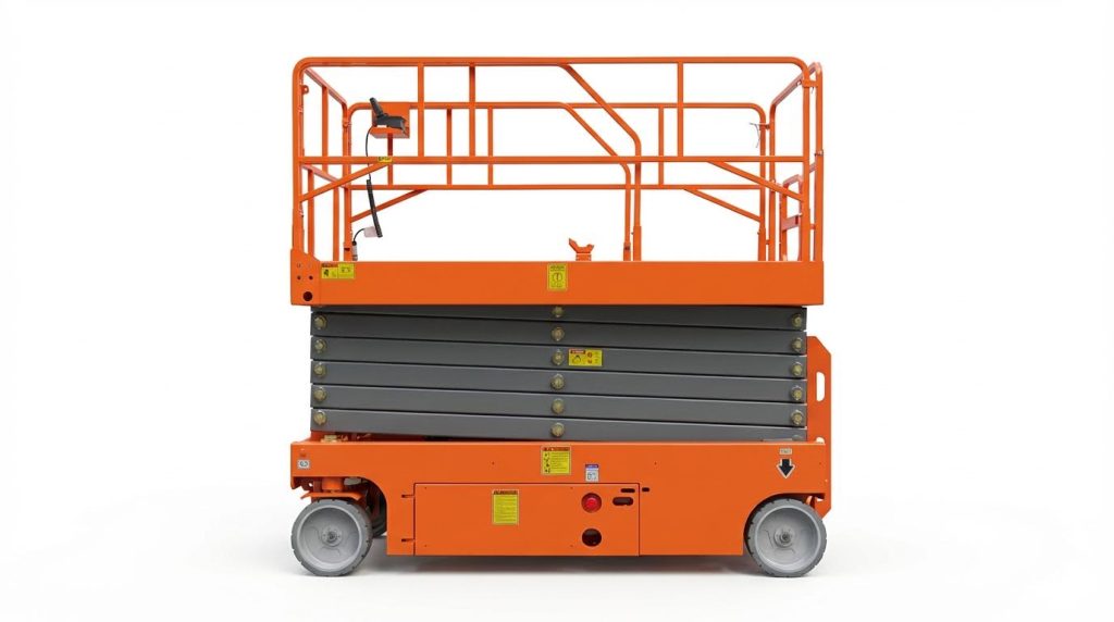
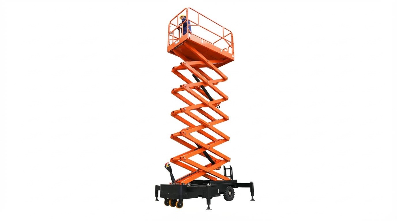
Platform length, width, and extension decks determine usable workspace and influence overturning stability. Typical access platforms around 2 260 mm by 1 130 mm with 900 mm extension must maintain adequate safety margins against tip-over at full outreach. Engineers calculate the center of gravity envelope for all load positions and verify that the resultant stays within the support polygon defined by wheels or outriggers. Compact dock lifts, such as 1 800 mm by 1 500 mm platforms in 1 900 mm by 1 600 mm pits, prioritize minimal clearance while preserving structural stiffness and deflection limits below practical thresholds, often less than L/300. Guardrail height, usually between 1.0 m and 1.2 m when raised, and foldable configurations affect both operator safety and transport height, so designers balance ergonomics with overall stowed dimensions.
Mobility, Turning Radius, And Ground Conditions
Mobility requirements distinguish fixed dock lifts from self-propelled electric scissor lifts used on construction or maintenance sites. Self-propelled units with 2-wheel hydraulic drive, 2-wheel steering, and turning radii between 2.2 m and 2.7 m must maneuver in aisles, around columns, and through doors, so wheelbase and track width selection becomes critical. Ground conditions dictate tyre size, ground clearance, and allowable gradeability; indoor smooth floors can use smaller tyres and 19 mm to 100 mm ground clearance, while outdoor sites may require higher clearance and lower travel speed. Designers must ensure the lift does not travel while elevated unless stability calculations and standards allow it, and integrate speed limits such as 3.5 km/h stowed and 0.8 km/h raised. For heavier dock or container lifts on casters, engineers specify swivel wheels, tow hitches, and leg stabilizers to cope with uneven loading and prevent excessive floor point loads.
Lifecycle Cost, Maintainability, And Modularity
Lifecycle requirements for an electric scissor lift cover energy consumption, scheduled maintenance, and downtime risk over the full service life. Battery systems, for instance 24 V lead-acid packs or 48 V configurations, represent major operating costs, so designers target efficient lifting speeds around 2 m/min to 6 m/min without oversizing motors. Maintainability drives choices such as swing-out trays for batteries and power units, modular cylinder assemblies, and accessible hose routing with anti-burst valves to simplify inspection and replacement. Engineers define maintenance intervals, such as hydraulic oil changes after 200 hours and annually thereafter, and design components so technicians can execute these tasks without special tools. Modularity in frames, scissor platform, and control packages allows manufacturers to cover multiple platform heights, from 6 m to 14 m, using common parts, which reduces inventory while supporting tailored duty profiles for different applications.
Mechanical And Electrical Subsystems Engineering
Mechanical and electrical subsystems define how to build an electric scissor lift that is safe, efficient, and durable. Designers must coordinate structural members, hydraulic circuits, drive systems, and controls as one integrated architecture. Each subsystem influences load rating, maximum platform height, duty cycle, and lifecycle cost. The following sections break down the key engineering decisions for each subsystem when developing new lift platforms.
Scissor Structure, Frames, And Fatigue Design
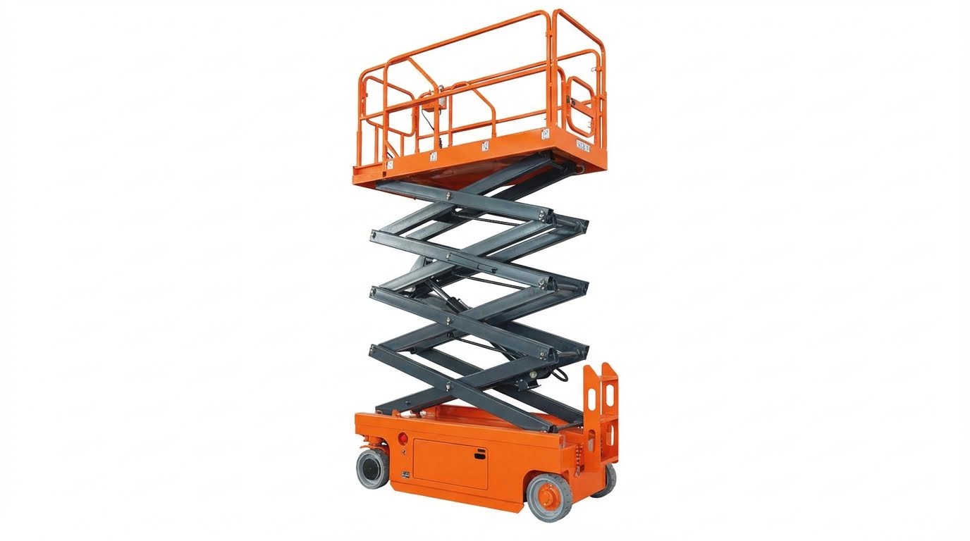
The scissor structure carries all vertical loads, dynamic impacts, and side forces during travel and lifting. Engineers typically use high-strength structural steel, such as rectangular hollow sections or channel sections, sized for the worst-case combination of rated load and self-weight. For example, a 3 000 kg, 6 m construction lift used 200 × 100 × 8 mm rectangular tubes and 20# channel steel to control deflection and local buckling. Welded joints require fatigue design, because repeated lifting cycles create stress ranges that can initiate cracks at weld toes and cutouts.
Finite element analysis helps verify stress distribution in the scissor arms and base frame under maximum load, braking, and wind loads. Designers check safety factors against yield and buckling, then run fatigue assessments for expected life, often 10 000 to 100 000 full cycles. Pins and bushings at each pivot must have adequate diameter, bearing length, and surface hardness to limit wear and ovalization. Grease grooves and seals reduce contamination and extend service intervals. Torsional stiffness of the base frame and platform frame is critical to keep platform height deviation within targets, such as ≤5% when multiple synchronized lifts operate together.
Hydraulic Circuits, Cylinders, And Burst Protection
Hydraulic actuation remains the dominant solution for lifting in electric scissor platforms due to high power density and smooth motion. Designers select cylinder bore and stroke from required force and travel, based on the worst mechanical advantage position of the scissor. For multi-unit synchronized systems, such as five linked 3-ton lifts, engineers often use a quad-cylinder arrangement with Φ100 mm cylinders and equal-length hoses to minimize height deviation. A DC pump station, for example 2.2 kW at 230 V DC, can supply the required flow and pressure for 4–6 m/min lift speeds.
Anti-burst or counterbalance valves mounted directly on cylinder ports prevent uncontrolled descent if a hose ruptures. Standards such as ISO 16368 required this type of protection for elevated work platforms. Designers set relief valves around 16 MPa, then verify that all components, including hoses and fittings, exceed this pressure with an adequate safety margin. Hose routing must avoid pinch points in the scissor mechanism and maintain minimum bend radii. Oil selection, for example HL-N46 within 0–40 °C, must match ambient conditions and duty cycle. Engineers also plan for bleeding air during commissioning and after long storage, and specify filtration to maintain cleanliness over the full service life.
Electric Drives, Batteries, And Power Management
Electric scissor lifts use battery power for both traction and hydraulic pumping, so energy budgeting is central when deciding how to build an electric scissor lift. Designers estimate total daily lifting work and travel distance, then size batteries and motors accordingly. Typical self-propelled models used 24 V systems with 3.3–4.5 kW lift motors and battery packs such as 4 × 6 V / 225 Ah or 4 × 6 V / 240 Ah. Higher-capacity or higher-voltage systems, such as 48 V 1 500 W drive wheels and 48 V hydraulic legs, can support heavier platforms and longer runtimes, often ≥3 hours continuous operation.
Traction motors must deliver enough torque for specified gradeability, for example 25%, while keeping travel speeds within limits, such as 3.5 km/h stowed and 0.8 km/h elevated. Power management logic typically disables drive motors while the platform lifts, and stops wheels when the main power is off, improving safety and range. Battery maintenance strongly affects lifecycle cost. Poorly maintained lead-acid batteries might last one year, while well-maintained units can reach three years. Designers increasingly adopt advanced battery monitoring, logging charge history, depth of discharge, and temperature to protect the pack. All-electric architectures with lithium-ion batteries and no hydraulics reduce routine maintenance and can cut energy consumption by about 70% through higher efficiency and energy recovery.
Control Architectures, Sensors, And Digital Twins
Control architecture defines how operators and safety systems interact with mechanical and hydraulic subsystems. Modern electric scissor lifts use distributed control, with a main controller in the chassis and an interface on the platform. These systems manage lift, drive, steering, stabilizers, and emergency functions. Safety interlocks disable drive when stabilizers deploy or when the platform exceeds allowable tilt. Sensing elements include tilt sensors, height limit switches, load sensors, and position feedback for cylinders or scissor angle. Additional devices, such as pothole protection switches and emergency descent controls, enhance safety in real-world conditions.
Engineers design the control logic to meet standards for elevated work platforms, implementing redundant stop paths and fail-safe states. For multi-lift systems, centralized controllers coordinate several units, maintaining height deviation within tight tolerances, for example ≤5% across five synchronized platforms. Remote controls and wired synchronization allow flexible site layouts while preserving safety. Digital twins increasingly support development and operation. A digital twin combines a physics-based model of the structure, hydraulics, and drives with real-time sensor data. Engineers can simulate duty cycles, optimize energy use, and predict component fatigue. During operation, the twin supports predictive maintenance by tracking cycles, temperatures, and vibration, then flagging cylinders, pins, or batteries that approach end-of-life before failure occurs.
Safety, Standards, And Reliability Engineering

Designers who study how to build electric scissor lift systems must treat safety, standards, and reliability as core engineering requirements, not add-ons. Regulatory limits, human factors, and fault behavior directly influence geometry, hydraulics, electrics, and controls. A robust design integrates guardrails, stability, interlocks, and diagnostics from the concept phase. This section links practical safety mechanisms with OSHA/ANSI/ISO frameworks so engineers can translate requirements into concrete design features and validation tests.
Guardrails, Fall Protection, And Human Factors
Guardrails define the primary fall protection system on an scissor platform and must meet scaffold-style requirements for height, strength, and continuity. Typical engineered solutions use foldable or retractable rails that lock positively with pins or bolts, reaching at least 1.0–1.2 m above the platform, with toe boards to prevent dropped tools. When you plan how to build electric scissor lift platforms, treat guardrails as part of the structural load path, verifying resistance to lateral loads and impact per OSHA 29 CFR 1926.451(g) and relevant ANSI A92 series clauses. Human factors analysis should address clear walkway width, gate design that prevents inadvertent opening, and control panel placement that avoids awkward reach or over-leaning. Designers should include visual cues, decals, and intuitive control layouts so operators naturally keep both feet on the deck and do not climb rails or use boxes to gain extra height.
Tip-Over Prevention, Stabilizers, And Ground Support
Tip-over prevention starts with a conservative stability envelope that covers maximum rated load, platform extension, and worst-case outreach. When defining how to build electric scissor lift frames and chassis, engineers should calculate static and dynamic stability factors on level ground and specified slopes, then validate through tilt testing. Stabilizers or hydraulic outriggers can increase the effective footprint and raise the allowable working height, but they must lock mechanically and include interlocks that prevent elevation unless fully deployed. Ground support design requires clear allowable ground pressure values, derived from wheel, caster, or leg contact areas and maximum load, so site engineers can verify suitability of concrete slabs, asphalt, or compacted soil. To manage wind loads, especially for outdoor models with 6–14 m platform heights, designers should specify maximum permissible wind speed, integrate tilt sensors and wind alarms, and derate capacity or restrict use when environmental limits are exceeded.
OSHA, ANSI, And ISO Compliance Considerations
Compliance engineering for scissor platform lift links mechanical and control design decisions to OSHA, ANSI, and ISO clauses that address access equipment and mobile elevating work platforms. OSHA 29 CFR 1910.27, 1910.28(b)(12), and 1926.451 historically defined scaffold and fall protection baselines, while ANSI A92 standards specified design, manufacturing, and safe-use requirements for scissor-type MEWPs. When defining how to build electric scissor lift systems for global markets, engineers should also reference ISO 16368 for mobile elevating work platforms, particularly for structural safety factors, stability tests, and hydraulic integrity. Compliance work products include design calculations, risk assessments, guarding layouts, electrical schematics, and test plans that demonstrate conformity with rated load, guardrail performance, braking capability, emergency descent, and interlock logic. Documentation must support operator training content, maintenance manuals, and safety decals so that regulatory intent flows through to field operation.
Predictive Maintenance, Monitoring, And Diagnostics
Reliability engineering for aerial platform benefits from embedding monitoring and diagnostics that anticipate failures instead of reacting to breakdowns. Modern designs increasingly integrate sensors for battery state-of-charge, charge history, and temperature, plus counters for lift cycles and drive hours, which support condition-based maintenance. Hydraulic health monitoring can track operating pressure, temperature, and lift speed trends, helping detect internal leakage, hose degradation, or contamination before they compromise safety. When you plan how to build electric scissor lift control architectures, include self-test routines at power-up, fault codes for emergency stop events, and data logging for overloads, tilt alarms, and near-miss conditions. Advanced fleets may connect these data to digital twins or cloud platforms, enabling predictive algorithms that optimize inspection intervals, extend battery life, and reduce unplanned downtime while maintaining compliance with inspection frequencies defined in standards and owner’s manuals.
Summary: Key Takeaways For Lift Design And Selection
Engineering teams planning how to build electric scissor lift systems should integrate structural, hydraulic, electrical, and control disciplines from the concept phase. The complete design process spans definition of load and height envelopes, scissor kinematics, power selection, digital control, and compliance with OSHA, ANSI, and ISO standards. Modern practice also emphasized predictive maintenance, battery management, and digital twins to reduce lifecycle cost while improving safety and availability.
From a technical standpoint, the first decision set covered rated load, working height, and duty cycle. Examples ranged from compact 15 000 kg dock lifts with 0.85–2.0 m stroke to 3 000 kg mobile units at 6 m and self-propelled access platforms with 6–14 m platform heights. These targets drove scissor section sizing, cylinder bore selection, pump power, battery voltage, and stability calculations for worst-case outreach and wind. Platform geometry, footprint, and turning radius then followed from use cases such as container loading, indoor maintenance, or multi-lift synchronized operation.
Safety and standards compliance formed the second pillar. Engineers aligned guardrail heights, access gates, and fall protection with OSHA 29 CFR 1926.451 and related clauses, and referenced ANSI A92 and ISO 16368 for design factors, stability testing, and hydraulic burst protection. Solutions such as anti-burst valves on each cylinder, leg stabilizers rated above maximum load, pothole protection, tilt sensors, and interlocks that disabled drive during elevation created layered protection. Tip-over resistance depended on conservative load charts, controlled travel speeds when raised, and restrictions on operation in wind above approximately 12.5 m/s.
Lifecycle cost and reliability considerations strongly influenced architecture choices when deciding how to build electric scissor lift fleets. All-electric concepts with sealed components, self-lubricating joints, and advanced battery monitoring reduced hydraulic complexity and extended service intervals. Conventional electro-hydraulic lifts still achieved high reliability when designers specified cleanable tanks, accessible hose routing, standard seal profiles, and diagnostic-friendly control layouts. Predictive maintenance based on sensor data, logged duty cycles, and alarm histories helped operators schedule oil changes, battery replacements, and structural inspections before failures.
Looking ahead, digital twins and connected control systems will shape how engineers design and validate electric scissor lifts. Virtual models of scissor mechanisms, hydraulic circuits, and drive systems will support simulation of synchronized multi-lift operation, emergency scenarios, and fatigue life before fabrication. On the operational side, cloud-connected controllers will report utilization, fault codes, and energy consumption, enabling data-driven fleet right-sizing and specification refinement. Designers who embed modularity, standard interfaces, and upgrade-ready electronics will position their lifts to adopt future technologies such as higher-density batteries or enhanced autonomy without complete redesign.
For practitioners selecting or specifying equipment, the key is to map application requirements to quantifiable parameters. Define maximum load, required working height, platform size, and ground conditions. Then compare candidate designs on stability margins, braking and interlock logic, battery endurance, and compliance documentation rather than only on initial price. A balanced approach to how to build electric scissor platform systems treated structural robustness, safety systems, powertrain efficiency, and maintainability as equally critical, delivering platforms that remained safe, productive, and economical over their full service life. Additionally, options like an aerial platform or scissor platform lift can enhance versatility in specific applications.

