This guide explains how to build electric scissor lift systems from an engineering perspective, focusing on geometry, powertrain, controls, and safety. You will see how design choices in structure, batteries, and standards translate into real-world stability, runtime, and compliance over the full lifecycle.
Core Architecture Of An Electric Scissor Lift
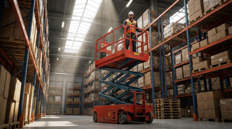
The core architecture of an electric scissor lift is the structural and geometric foundation that makes vertical lifting stable, predictable, and safe, and it is the first thing you must engineer when planning how to build electric scissor lift systems. It defines how loads flow from the platform through the scissor platform into the chassis and wheels, and how the machine behaves as height, outreach, and floor conditions change.
Scissor geometry and load paths
Scissor geometry and load paths describe how the crossed beams, pivots, and actuator convert force into vertical motion while spreading loads safely into the base frame. If you ignore this, the lift may feel “soft,” twist under load, or overstress key joints long before reaching rated capacity.
The scissor pack is essentially a series of paired steel arms pinned in a criss-cross pattern that translates actuator force into vertical elevation. Properly designed, it distributes load to prevent localized stress and fatigue cracking under frequent cycling. Technical review of small electric scissor lifts explains that the geometry must keep stresses balanced across the arms and pivot points during the full stroke.
| Design Aspect | Typical Engineering Approach | Operational Impact |
|---|---|---|
| Scissor arm material | High-strength steel profiles sized from static + dynamic load calculations | Resists bending when platform carries 150–450 kg payloads at up to ~16 m working height |
| Pivots and pins | Hardened pins with plain or roller bearings; friction coefficient ~0.15–0.25 (plain) or 0.001–0.005 (roller) | Lower friction reduces actuator force and wear, improving smoothness and service life |
| Actuator position | Mounted near base with optimized lever arm using scissor-lift force calculators | Minimizes peak force at full collapse, allowing smaller hydraulic or electric actuators |
| Load distribution | Load path modeled from platform through arms into chassis nodes | Prevents local overstress at welds and joints under frequent use |
Industrial scissor lift design practice uses static load analysis plus an allowance for dynamic forces from acceleration and deceleration. One engineering reference notes that dynamic effects can add around 3% to the static load, and that friction coefficients range from 0.15–0.25 for plain bearings and 0.001–0.005 for roller bearings, which strongly affects actuator sizing and efficiency. Industrial scissor lift platforms and actuator sizing also highlights the use of dedicated scissor lift calculators to determine peak actuator force from geometry and load.
- Centralized load path: Keep the platform load centered over the scissor platform lift – this reduces torsion and side loading on the arms.
- Symmetrical arm layout: Use matched left/right arm sets – symmetry keeps the lift tracking straight during extension.
- Generous pin diameters: Size pins for shear and bearing with fatigue in mind – this mitigates ovalization of holes over thousands of cycles.
- Stiff platform frame: Design the deck as a rigid diaphragm – it spreads operator and tool loads evenly into the top arm connections.
How scissor geometry affects actuator force
When the scissor is nearly collapsed, the actuator works at a very poor mechanical advantage, so required force peaks. As the lift rises, the force drops. That is why engineers use geometry-based calculators to size actuators and often overspecify the drive end hardware closest to the base. Actuator sizing guidance emphasizes this peak-force-at-bottom behavior.
💡 Field Engineer’s Note: If you want a compact electric scissor lift that still feels rigid at full height, prioritize deeper arm sections and tight pin-to-bore clearances rather than just increasing steel thickness; sloppy pivots cause more “wobble” than slightly flexible beams.
Chassis, wheelbase, and stability envelope
The chassis, wheelbase, and stability envelope define how the scissor stack connects to the ground and how far you can safely push height, load, and travel without tipping. This is where structural engineering meets real-world floor conditions, gradients, and tight aisles.
The chassis carries the scissor pack, batteries, drive motors, and control systems, and it must remain rigid while keeping the footprint small enough for indoor access. Technical reviews of compact electric scissor lifts describe chassis designs with short wheelbases and narrow widths that still maintain rigidity for stability, with balanced weight distribution to improve steering, reduce tire wear, and support elevated platform operation. Technical review of small electric scissor lifts emphasizes this balance between compactness and stiffness.
| Chassis / Stability Parameter | Typical Values or Design Direction | Operational Impact |
|---|---|---|
| Working height | About 4–16 m working height depending on model | Sets required wheelbase and outrigger (if any) strategy for stability |
| Platform capacity | Typically 150–450 kg for 1–2 operators plus tools | Higher capacity demands wider base and stronger frame sections |
| Turning performance | Compact units can turn in ≤1.5 m radius; drive speed ~0.8–1.2 m/s on some models | Allows operation in narrow aisles while keeping movements smooth and controllable |
| Drive speed (stowed vs elevated) | Stowed up to about 4 km/h, elevated about 0.8 km/h on certain self-propelled lifts | Reduced elevated speed helps keep dynamic loads and tipping risk under control |
| Gradeability / slope capability | Some industrial scissors are limited to 3–5°; other self-propelled models reach 25–30% grade when stowed | Defines whether the unit is strictly indoor/level-floor or can handle ramps between levels |
| Tire type | Solid, non-marking tires for indoor and light outdoor use | Protects finished floors and reduces puncture risk in warehouses and retail spaces |
| Overall machine weight | Roughly 1,500–3,000 kg for many self-propelled electric scissor lifts | Drives floor loading checks and transport requirements (trailers, forklifts, etc.) |
One self-propelled electric scissor lift specification describes platform heights of 6–14 m with working heights of 8–16 m and platform capacities of 230–450 kg, combined with stowed drive speeds around 4 km/h and elevated speeds around 0.8 km/h. Gradeability is listed in the 25–30% range for some models, and total machine mass can range from about 1,500–3,000 kg. The same reference notes the use of solid non-marking tires, proportional joystick controls, tilt sensors, and overload protection as integral parts of the architecture. Self-propelled electric scissor lift specifications shows how these parameters work together in real products.
- Wide-enough wheelbase: Size wheelbase and track to keep the combined center of gravity inside the support polygon at maximum height – this is the core of your stability envelope.
- Rigid chassis box: Use closed-section longitudinal and cross members – this prevents “racking” when the platform is offset loaded.
- Balanced component layout: Place batteries and hydraulic power unit low and centrally – this lowers the center of gravity and improves steering.
- Floor compatibility: Match machine weight and wheel loads to rated floor capacity – critical for mezzanines and elevated slabs.
Stability envelope and standards
The stability envelope defines allowable combinations of height, load, slope, and wind. European standard EN 280 and North American ANSI A92 series set requirements for design, testing, and operational safety of mobile elevating work platforms, including scissor lifts, and are used to validate that the machine resists overturning under prescribed test conditions. EN 280 and ANSI A92 references and compliance summaries both highlight these standards.
💡 Field Engineer’s Note: When you map out how to build electric scissor lift prototypes, always test worst-case: full height, rated load, slight slope, and a quick steering input; if the chassis twists or the wheels unload, you need more torsional stiffness or a wider stance before going to production.
Key Components And Engineering Design Choices
This section explains how core components and design choices determine performance, safety, and cost when you plan how to build electric scissor lift systems for real-world duty cycles.
When you decide how to build electric scissor lift platforms, three subsystems dominate engineering tradeoffs: actuation, energy storage, and control/safety architecture. Getting these right prevents chronic failures, battery complaints, and instability incidents.
Actuation: hydraulic vs electric linear systems
Actuator selection for an electric scissor lift is a balance between force density, control precision, maintenance, and lifecycle cost.
Most compact electric scissor lifts today still use an electric-driven hydraulic power pack feeding one or more cylinders to drive the scissor stack. Travel is handled by DC traction motors with reduction gearboxes that give precise low-speed control for tight maneuvering. Technical review of small electric scissor lifts
| Actuation Technology | Typical Use in Scissor Lifts | Key Engineering Characteristics | Operational Impact |
|---|---|---|---|
| Hydraulic cylinder + electric pump | Common in self-propelled electric scissors | Very high force density, compact cylinder, smooth motion; needs oil, hoses, seals | Best for 6–16 m working height with 230–450 kg loads where robustness matters. |
| Electric linear actuator | Used in lighter industrial platforms | Energy efficiency about 70–85%, precise position control, minimal maintenance | Ideal for clean indoor environments and applications needing accurate level stops. |
| Pneumatic cylinder | Special applications, light duty | Lower force, position accuracy about ±10 mm | Suited to low-load, non-personnel platforms where air is already available. |
Hydraulic systems deliver very high force in a small envelope, which is why they dominate compact personnel lifts. However, they introduce leak risk, temperature-sensitive viscosity, and periodic seal replacement. Electric linear actuators remove hydraulic oil from the design and give finer electronic control, but you must size them carefully for peak scissor forces and duty cycle to avoid overheating. Actuator technology selection and efficiency
Simplified actuator sizing logic
To size an actuator, start from the worst-case load at minimum platform height, where the scissor angle gives the highest mechanical disadvantage. Include platform self-weight, maximum payload, and an allowance for dynamic effects. Static analysis adds payload, platform, and any fixtures, while dynamic forces from acceleration and deceleration typically add around 3% to the static load. Friction coefficients for plain bearings are around 0.15–0.25, while roller bearings are around 0.001–0.005, heavily influencing required force. A dedicated calculator can determine peak actuator force from geometry and friction inputs. Scissor lift force calculation
- Hydraulic choice: Use when you need compact high force with simple mechanics – ideal for 230–450 kg platforms up to about 16 m.
- Electric linear choice: Use where clean operation and precise control beat raw force – reduces maintenance and simplifies control integration.
- Check duty cycle: Match actuator rating (25–100% duty cycle) to how often you expect to lift – prevents motor overheating and nuisance shutdowns.
Duty cycle is critical: intermittent use suits actuators rated around 25–30% duty cycle, frequent operation needs 50–60%, and near-continuous cycling demands 80–100% duty cycle plus enhanced cooling measures. Duty cycle considerations
💡 Field Engineer’s Note: If you use hydraulic actuation in cold storage (around 0°C or below), specify low-temperature fluid and oversize the reservoir. Thick oil dramatically slows lift speed and can trip tilt or overload protections because the platform reacts sluggishly.
Battery technology, duty cycle, and power sizing
Battery selection and sizing define how long your electric scissor lift runs per charge, how heavy it is, and how operators perceive reliability.
Modern electric scissor lifts typically use 24 V or 48 V DC battery systems to power traction motors and the hydraulic power pack or electric actuators. Typical power sources and specs Traditional designs rely on lead-acid batteries, while newer platforms increasingly adopt lithium-ion packs for higher energy density, lower weight, and longer runtime. Battery system evolution
| Battery Type | Typical Runtime per Charge | Typical Charging Time | Operational Impact |
|---|---|---|---|
| Lead-acid (flooded/AGM) | About 4–6 hours intermittent operation | About 6–8 hours | Heavier, cheaper; suits single-shift, overnight-charge fleets. |
| Lithium-ion | About 6–8 hours | About 2–4 hours | Lighter, fast charge; supports opportunity charging and multi-shift duty. |
Lead-acid systems remain attractive on cost, but they need water maintenance and tolerate fewer deep cycles. Lithium-ion reduces overall machine weight and improves maneuverability, while fast charging allows top-up during breaks. Lead-acid vs lithium-ion performance Typical self-propelled electric scissor lifts with 6–14 m platform height and 230–450 kg capacity use 24–48 V systems and require 6–8 hours to fully recharge when using conventional chargers. Example battery and charge specs
- Define duty cycle: Estimate lifts per hour and drive distance – this sets Ah capacity and charger power.
- Allow safety margin: Add reserve for cold days and aging – prevents mid-shift brownouts and slow lifts.
- Integrate protections: Design for low-battery alarms and controlled descent – keeps personnel safe even with weak batteries.
Well-engineered lifts integrate power management that prevents continuous lifting, warns at low state-of-charge, and still guarantees a safe, controlled descent when the battery is nearly depleted. Duty cycle and power management
Linking duty cycle to fleet usage
For a warehouse using lifts intermittently over an 8-hour shift, a battery configuration that delivers 4–6 hours of actual movement time is usually adequate because the lift spends much of the day idle. For high-utilization sites where platforms run close to continuously, you should treat the application as 50–60% or higher duty cycle and favor lithium-ion plus opportunity charging to avoid oversizing the pack excessively. Duty cycle guidance
💡 Field Engineer’s Note: When operators complain that “the lift is slow,” it is often a voltage sag issue, not a hydraulic fault. Undersized or sulfated batteries drop voltage under load, cutting pump speed. Always log voltage at full lift demand before blaming the hydraulics.
Controls, sensors, and safety interlocks
Control architecture and safety interlocks ensure that even when operators make mistakes, the electric scissor lift stays stable and predictable.
Modern electric scissor lifts use low-voltage control systems that coordinate drive, lift, and safety functions through proportional joysticks and logic modules. These systems provide smooth acceleration and deceleration, status indication, and emergency stop capability at both platform and ground controls. Control system and operator interface Control system and safety features
| Control / Safety Feature | Engineering Role | Typical Implementation | Operational Impact |
|---|---|---|---|
| Proportional joystick controls | Modulate speed and lift rate | Low-voltage joystick with proportional valves or motor controllers | Allows fine positioning at height and smooth starts/stops in tight spaces. |
| Emergency stop buttons | Immediate power cut to motion circuits | Mushroom-type switches at platform and base | Lets operators or spotters instantly halt unsafe movement. |
| Tilt sensor | Monitor chassis angle | Electronic inclinometer feeding control logic | Disables lift when tilt exceeds safe threshold to prevent tip-over. |
| Overload protection | Prevent lifting beyond rated capacity | Load-sensing pins or pressure-based calculation | Stops lift with excessive weight, preserving stability and structure. |
| Floor irregularity detection | Detect unsafe terrain | Sensors or logic reacting to wheel position differences | Can lock motion if floor steps or holes exceed about 10 mm. |
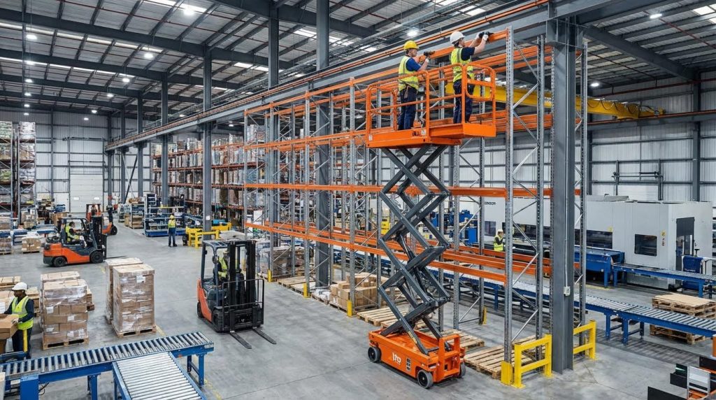
Typical working heights of 4–12 m and capacities of 150–320 kg already push stability limits, so the control system must enforce safe behavior. Some designs monitor floor irregularities above about 10 mm and automatically lock motion to avoid sudden tilting. Working height, capacity, and floor detection Guardrails and structural elements must comply with standards such as EN 280 and ANSI A92 for aerial platforms, and OSHA fall protection rules require that guardrail systems remain in good condition and workers stand only on the platform, not on the rails. Guardrail and fall protection requirements
- Interlock philosophy: Design the logic so that unsafe conditions default to “no motion” – prevents operators from bypassing protections during rush jobs.
- Pre-use checks: Ensure controls, brakes, tilt sensors, and emergency stops are part of daily inspections – catches failures before they turn into incidents.
- Standard compliance: Align design with EN 280, ANSI A92, and OSHA rules – simplifies certification and reduces liability.
Control and safety checklist when designing a new lift
When you plan how to build electric scissor lift controls from scratch, include: low-voltage proportional joysticks for both drive and lift; redundant emergency stops; an inclinometer linked to lift inhibit logic; overload sensing tied to capacity labels; travel speed reduction when elevated; and an emergency lowering system that works even with a flat battery. Also design for pre-operation checks of brakes, tires, hydraulic fluid, and battery condition, as required by safety guidance. Preventive maintenance and inspection Operational maintenance checklist
💡 Field Engineer’s Note: Never rely on software alone for critical interlocks like overload and emergency stop. Always pair electronic logic with hardwired relays or contactors so that a single controller fault cannot allow unintended motion.
Designing For Applications, Compliance, And Lifecycle
Designing for applications, compliance, and lifecycle means sizing an electric scissor lift to real work, certifying it to standards, and planning maintenance so performance and safety remain stable over 10–15 years. If you are learning how to build electric scissor lift platforms, this is the point where theoretical design becomes a compliant, maintainable product.
In practice, you match height and capacity to tasks, engineer maneuverability around aisles and doors, then lock the design to EN 280 / ANSI A92 rules and a realistic service plan.
Matching height, capacity, and maneuverability
Matching height, capacity, and maneuverability means choosing platform size, load rating, and drive geometry so the lift actually fits the building and the job profile. For anyone studying how to build electric scissor lift equipment, these are the first application constraints you convert into hard numbers.
Use working height, platform capacity, and turning radius as your primary design dials, then back‑check against stability and duty cycle.
| Parameter | Typical Range / Value | What To Design Around | Operational Impact |
|---|---|---|---|
| Platform height | 6–14 m | Ceiling height + 1.5–2.0 m for reach | Determines building class served (retail vs logistics hall) Platform height data |
| Working height | 8–16 m | Max task height (lights, racks, façade) | Ensures operators work within ergonomic chest height, not overhead strain Working height data |
| Platform capacity | 150–320 kg; some 230–450 kg | People + tools + materials (include 15–25 kg pallet if used) | Defines 1‑person service vs 2‑person installation tasks 150–320 kg range 230–450 kg range |
| Turning radius | ≤1.5 m (compact) | Warehouse aisle width and door clearances | Allows turning inside typical 2.5–3.0 m aisles without shunting Turning radius data |
| Drive speed (stowed / elevated) | 4 km/h stowed; 0.8 km/h elevated | Site size and required repositioning frequency | Balances productivity with safe stopping distance at full height Drive speed data |
| Duty time per charge | 4–6 h (lead‑acid); 6–8 h (Li‑ion) | Shifts per day and breaks available for charging | Determines battery chemistry and Ah rating for your design Battery runtime data |
- Define tasks first: List max working height, number of operators, and typical load – this becomes your core design envelope.
- Use worst‑case loads: Add pallet, fixtures, and tools to person mass – prevents overload trips during real work.
- Protect lateral stability: Derate capacity at max height if necessary – keeps center of gravity within the stability polygon.
- Align wheelbase with aisle width: Short wheelbase and narrow chassis – improves steering and reduces tire scrub in tight spaces.
- Size batteries for the true duty cycle: Compare 25–30% vs 50–60% duty – avoids thermal stress on motors and actuators.
How to translate a user requirement into scissor lift specs
Take an example requirement: “Change lights in a 9 m warehouse with 2 people and 60 kg of tools.” You should target a working height of 10–11 m, platform height about 8–9 m, and platform capacity ≥260–300 kg. Verify aisle width; if aisles are 2.6 m, you design for a turning radius ≤1.3 m and a chassis width around 1.0–1.2 m so the machine can rotate inside the aisle without multi‑point turns.
💡 Field Engineer’s Note: When you push platform height beyond 10–12 m on a narrow chassis, dynamic sway becomes the real limiter, not static strength. Build extra stiffness into the scissor pack and chassis or you will hit EN 280 stability and tilt‑sensor limits long before you hit the steel’s stress limits.
Standards, floor conditions, and maintenance strategy
Designing for standards, floor conditions, and maintenance means building your electric scissor lift to pass EN 280 / ANSI A92 tests, survive the site flooring, and stay safe with realistic daily and annual service. This is where a “how to build electric scissor lift” project either becomes a certifiable machine or stays a prototype.
Lock in your target markets first (EU, US, other), then design structural strength, electrics, and service access around those rules and the expected environment.
| Design Axis | Key Requirements / Data | Design Implication | Operational Impact |
|---|---|---|---|
| Regulatory standards | EN 280, ANSI A92, CE, ISO 9001, UL 583, RoHS | Define load tests, stability, guardrails, electrical safety, documentation Standards list | Machine is legally usable in target regions and easier to insure. |
| Guardrails and fall protection | Guardrails required; OSHA 29 CFR 1926.451(g) / 1910.29(b) | Design rail height, toe‑boards, and gates to spec OSHA guardrail requirement | Reduces fall risk; non‑compliant rails can block site approval. |
| Floor flatness and condition | Designed for firm, level, load‑rated floors; floor irregularities >10 mm may lock motion | Specify max floor slope (3–5°) and roughness your design tolerates Floor condition data | Operators know where lifts are allowed; reduces tip and chassis damage risk. |
| Gradeability | 3–5° for small indoor units; some self‑propelled models 25–30% when stowed | Drive motor torque and wheelbase must support ramps only when lowered 3–5° slope data 25–30% gradeability data | Safe travel on loading‑bay ramps when platform is fully retracted. |
| Tires and floor protection | Solid, non‑marking tires for indoor/outdoor smooth floors | Wheel load and tire width sized to floor bearing limits Tire type data | Prevents slab damage and black marks in retail, hospitals, and offices. |
| Noise and emissions | <70 dB(A), zero local emissions | Electric drive and hydraulic damping tuned for quiet operation Noise data | Makes the design acceptable in hospitals, malls, and public buildings. |
| Maintenance intervals | Daily, weekly, monthly, annual checklists | Provide access points, grease nipples, and inspection windows Maintenance schedules | Reduces downtime and keeps the machine compliant over its lifecycle. |
- Design around OSHA / EN 280 from day one: Do not “retrofit” guardrails or interlocks – retrofits are costly and may still fail certification.
- Specify operating surfaces clearly: Put max slope and floor type in the manual and on decals – this shapes user behaviour and reduces misuse.
- Build serviceability into the chassis: Side doors, swing‑out trays, and labelled test points – cut maintenance hours and error risk.
- Standardize maintenance tasks: Align daily/weekly/monthly checks with your component life estimates – so inspections actually catch fatigue and leaks in time.
- Integrate safety systems with maintenance: Make tilt sensors, overload devices, and emergency lowering easy to test – operators can verify function before every shift.
Typical maintenance framework to design for
Your design should realistically support: daily cleaning and visual checks of platform, controls, hydraulic oil level, and electrical connections; weekly battery load tests, greasing of joints and pivots, and functional checks of emergency stops and tilt sensors; monthly tire inspection, cylinder leak checks, and cleaning of battery terminals; annual full mechanical inspection, replacement of worn parts, and renewal of safety certifications. These tasks align with common manufacturer recommendations and OSHA’s requirement for regular preventive maintenance.
💡 Field Engineer’s Note: If technicians need to remove covers with dozens of bolts just to reach a hose or battery, they will skip inspections when the site is busy. Design wide‑opening panels and safe, supported access at ground level; it is the cheapest way to keep your lift compliant and out of the accident reports.
Final Engineering Considerations And Design Tradeoffs
Engineering an electric scissor lift means balancing geometry, stability, power, and safety into one coherent system. Scissor arm layout, pin sizing, and actuator position set the structural backbone. Chassis width, wheelbase, and component placement then shape the stability envelope and define where the machine can safely work. Actuation, batteries, and controls convert this structure into reliable motion, runtime, and protection against misuse.
These choices interact. A taller platform height drives heavier arms and a wider base. Higher capacity demands stronger sections, more actuator force, and larger battery reserves. Tighter aisles push you toward a narrower chassis, which in turn requires stricter limits on load, height, and speed. Control logic, sensors, and interlocks must enforce these limits every day, not just on the drawing board.
The best practice for engineering and operations teams is clear. Start from real tasks, floors, and duty cycles. Design within EN 280, ANSI A92, and OSHA rules from day one. Prioritize stiffness, low center of gravity, and fail-safe controls. Finally, build easy maintenance access into every Atomoving scissor lift so inspections stay quick, honest, and consistent over the full lifecycle.
Frequently Asked Questions
How do electric scissor lifts work?
An electric scissor lift operates using a hydraulic or pneumatic system. When powered on, the system fills cylinders with hydraulic fluid or compressed air. This pressure pushes the cylinders outward, causing the scissor legs to extend and the platform to rise. Scissor Lift Mechanics.
How to raise and lower a scissor lift?
To raise or lower an electric scissor lift, locate the horizontal switch on the control panel. Flip the switch left to activate the hydraulics and allow the platform to move up or down. Ensure the switch is set correctly before operation. Safe Scissor Lift Operation.
How to operate a lift step by step?
Start by inserting the key into the brake release switch at the back of the lift and turning it. This allows you to move the lift manually if needed. Next, power on the lift and use the control panel to manage its movement. Always follow safety protocols during operation.

