Electric scissor lifts use battery-powered electric drives to actuate hydraulic or mechanical linkages that raise a guarded work platform vertically. Understanding how these machines work requires looking at their structural architecture, powertrains, control logic, and integrated safety systems as a whole. This article explains core components and load paths, power and actuation technologies, control and safety circuits, and how these elements combine into compliant, reliable access equipment. Engineers and fleet managers can use these principles to evaluate designs, optimize operation, and plan safe, cost-effective deployment of scissor platform lift and other similar equipment like aerial platform.
Core Architecture Of Electric Scissor Lifts
Understanding how electric scissor lifts work starts with their core architecture. Structural members, actuators, and control hardware form an integrated system that converts battery energy into safe vertical motion. The chassis, scissor stack, and platform manage loads, while electric, hydraulic, and mechanical subsystems generate and transmit force. Performance limits, such as duty cycle, stability, and gradeability, define where engineers can safely deploy these lifts.
Main Structural Components And Load Paths
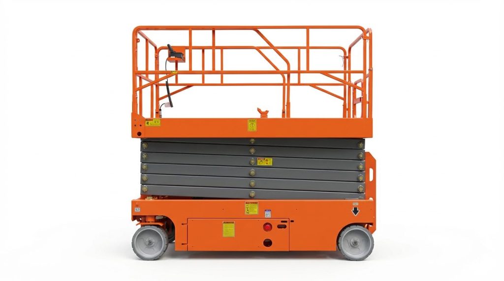
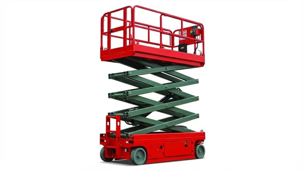
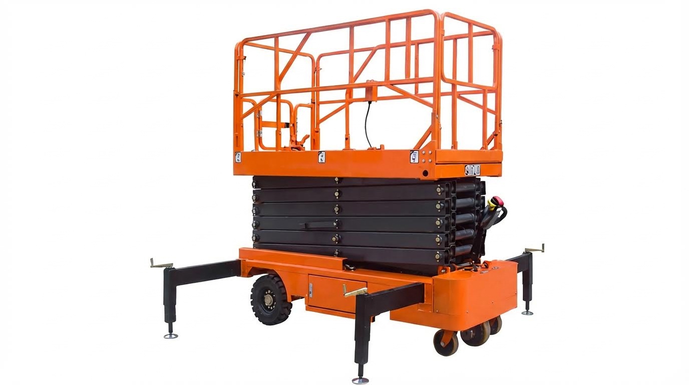
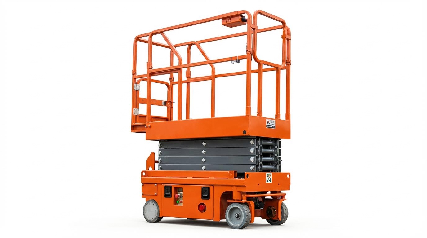
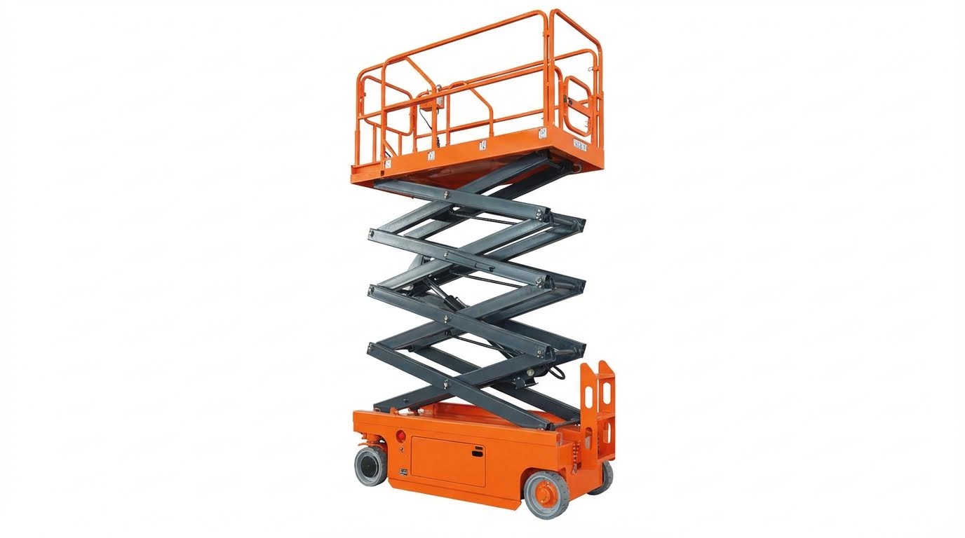
The primary structure consists of the chassis, scissor stack, and work platform with guardrails. The chassis carries the machine’s dead weight, the rated load, and dynamic loads during driving and lifting. Engineers design the chassis as a welded steel frame that distributes vertical loads into the wheel contact patches in a predictable path. The scissor stack uses crossed, pin-connected arms that form a pantograph, converting cylinder or screw extension into vertical motion. Load paths travel from the platform through the scissor arms, pins, and base weldments into the ground. Guardrails, toe boards, and gates provide fall protection and must withstand specified lateral forces according to relevant standards. Stiffness, not only strength, controls deflection and platform stability at full height.
Electric, Hydraulic, And Mechanical Subsystems
Electric scissor lifts typically use a DC battery pack feeding an electric motor that drives a hydraulic pump. The hydraulic subsystem then pressurizes one or more cylinders that extend the scissor stack to raise the platform. Return flow to the tank, controlled by proportional or on–off valves, lowers the platform in a controlled manner. Mechanical elements include pivot pins, bearings, linkages, and the drive axle or wheel motors that provide horizontal travel. In hybrid architectures, electric motors may directly drive wheel hubs, while hydraulics handle only lifting. Designers size conductors, hoses, and components to limit pressure drop, voltage drop, and heat generation over the full duty cycle.
Typical Performance And Duty-Cycle Parameters
Typical compact electric scissor lifts achieve platform heights from about 6 m to 11.8 m, with working heights up to roughly 13.8 m. Rated platform capacities often reach 300 kg, including operators, tools, and materials. Extended deck sections usually carry lower loads, around 100 kg to 113 kg, because of increased bending moments. Closed machine heights with guardrails up range from about 2.15 m to 2.53 m, and with rails folded or removed from 1.19 m to 1.57 m. Typical machine footprints are roughly 2.40 m in length and 1.15 m in width, with platform sizes near 2.27 m by 1.15 m plus about 0.9 m of extension. Travel speeds usually reach about 3.5 km/h stowed and 0.8 km/h elevated, balancing productivity with stability. Lift and lower times of 70 s to 80 s limit dynamic loads and improve control. Engineers define duty cycles based on expected daily operating hours, lift cycles, and travel distances to size batteries, motors, and cooling provisions.
Design Limits: Stability, Gradeability, And Reach
Stability governs how electric scissor lifts work safely at height. Designers control the relationship between wheelbase, track width, center of gravity, and maximum working angle. Typical allowable chassis tilt during operation is about 2° to 3°, verified by tilt sensors that inhibit unsafe movement. Minimum ground clearance around 110 mm when stowed and about 20 mm when elevated limits underbody contact while maintaining a low center of gravity. Wheelbases near 1.85 m and outer turning radii around 2.1 m provide maneuverability in tight aisles. Gradeability values near 20% define the maximum slope the machine can climb in the stowed condition. Standards require that the combined center of gravity of machine and rated load remains within a defined stability polygon under wind, braking, and steering loads. Engineers validate these limits through static calculations and dynamic tests, then implement interlocks that restrict drive speed or lift function when sensors detect unsafe conditions.
Powertrains, Actuation, And Energy Management
Powertrains define how electric scissor lifts convert stored electrical energy into vertical motion and drive torque. Understanding how electric scissor lifts work requires tracing energy from the battery pack through motors, hydraulic or mechanical actuators, and control electronics. Engineering choices in battery chemistry, motor topology, and actuation architecture directly affect duty cycle, noise, emissions, and maintenance. This section explains the internal workings of these systems and shows how design decisions influence lifecycle cost and fleet productivity.
Battery Systems, Charging, And Lifecycle Costs
Electric scissor lifts typically use 24 V battery packs assembled from four 6 V deep-cycle batteries. These batteries supply traction, lifting, and control circuits through contactors and solid-state controllers. Properly maintained lead-acid batteries usually delivered 2–3 years of service in typical rental duty, while neglected packs often failed within one year. Engineers specified ampere-hour ratings and maximum discharge currents so that a lift could complete a full shift without dropping below recommended depth of discharge.
Charging strategies strongly influenced how electric scissor lifts work in daily operations. Integrated 24 V chargers matched to the battery chemistry controlled charge current and voltage to limit gassing and plate sulfation. Opportunity charging during breaks extended usable runtime but required thermal management to avoid overheating cells. Designers also considered plug accessibility and cable routing to prevent damage in tight warehouse environments.
Lifecycle cost analysis compared battery replacement, energy consumption, and maintenance labor. Cleaning battery banks and terminals reduced surface leakage currents and preserved capacity. Regular water top-up in flooded lead-acid designs prevented plate exposure and capacity loss. Advanced monitoring systems with current, voltage, and temperature sensing allowed fleet managers to predict end-of-life and schedule replacements, reducing unplanned downtime.
Electric Motors, Pumps, And Lift Actuation
In conventional electric scissor lifts, a DC or AC traction motor drove both travel and lifting through separate circuits. For lifting, the motor coupled to a hydraulic pump that pressurized fluid for one or more cylinders in the scissor stack. When an operator commanded “up,” the controller energized the motor, the pump increased system pressure, and cylinders extended, forcing the scissor arms to open and raise the platform. For “down,” a proportional valve released fluid back to the tank, allowing gravity to retract the mechanism in a controlled manner.
Traction used a separate motor channel or a dual-function motor with directional control through contactors or inverters. The powertrain controller limited acceleration, deceleration, and maximum speed to maintain stability, especially when the platform was elevated. Typical closed-platform travel speeds reached about 3.5 km/h, while elevated speeds reduced to roughly 0.8 km/h to control dynamic loads. Designers tuned motor torque limits and ramp profiles to avoid sudden shocks to the scissor structure and occupants.
How electric scissor lifts work in real sites depended on matching motor power to hydraulic demand. Pump displacement and motor rating set lift speeds, often in the 70–80 s range from full retraction to maximum height. Engineers balanced faster lift times against battery drain and heat generation in the hydraulic circuit. High-efficiency motors, low-leakage valves, and optimized hose routing reduced energy losses, extending runtime per charge and lowering operating temperature.
All-Electric, Zero-Hydraulic Lift Technologies
Newer designs replaced hydraulic circuits with fully electric actuation to eliminate leaks and reduce maintenance. Instead of cylinders, these lifts used screw drives, rack-and-pinion systems, or electric linear actuators integrated into the scissor stack. An electric motor drove each actuator through gearboxes, converting rotary motion into linear extension. Position sensors fed back stroke information to the controller, enabling precise platform height control without hydraulic fluid.
These all-electric systems changed how electric scissor lifts work from an energy perspective. They removed pump idling losses, valve throttling losses, and fluid shear heating. With fewer moving parts and no hoses, they reduced failure modes related to contamination, seal wear, and hose fatigue. Self-lubricating pins and bushings further cut routine greasing tasks. However, designers needed to manage backlash, screw wear, and potential jamming, often by adding torque sensing and current monitoring to detect abnormal loads.
All-electric lifts often paired with high-energy-density lithium-ion batteries. This combination enabled longer runtimes, opportunity charging, and energy recovery during platform lowering or deceleration. Control algorithms captured regenerative energy back into the battery instead of dissipating it as heat. The result was lower total energy consumption per operating hour and cleaner operation in indoor or sensitive environments.
Predictive Maintenance And Smart Monitoring
Modern electric scissor lifts integrated sensors and connectivity to support predictive maintenance. Current, voltage, and temperature sensors on the battery and powertrain tracked charge cycles, depth of discharge, and thermal stress. Vibration and position sensors on actuators and scissor pivots detected abnormal motion patterns that indicated wear or misalignment. Controllers logged fault codes, duty cycles, and overload events, building a data history for each unit.
Understanding how electric scissor lifts work in the field required analyzing this data at fleet level. Cloud or local fleet management systems aggregated logs to identify recurring issues, such as chronic undercharging or operation on excessive slopes. Algorithms estimated remaining useful life for batteries, contactors, and actuators based on measured stress rather than fixed calendars. Maintenance teams could schedule service windows before failures, reducing unplanned downtime and rental penalties.
Smart monitoring also improved safety and energy management. Systems could derate lift speed or height when batteries dropped below safe thresholds, preventing brownouts at elevation. Remote diagnostics allowed technicians to review error codes and sensor traces before visiting a site, improving first-time fix rates. Over time, feedback from monitoring informed design changes, such as reinforcing high-stress joints or revising software limits on gradeability and platform loading.
Control Logic, Safety Circuits, And Compliance
Control logic in electric scissor lifts coordinates power delivery, motion commands, and safety functions to answer a core question: how do electric scissor lifts work in real job sites. The control system links platform inputs, drive systems, lift actuation, and feedback sensors into a closed loop. Safety circuits overlay this logic with mandatory interlocks and emergency functions that comply with standards such as EN 280 and ANSI A92. Digital monitoring and fleet tools now extend this control layer across entire equipment fleets for higher uptime and traceability.
Platform Controls, Drive Systems, And Feedback
Platform controls form the primary human–machine interface and determine how electric scissor lifts work from the operator’s perspective. A typical console includes key switch, enable switch, joystick or proportional toggles, lift and drive selectors, and emergency stop. When the operator commands lift or travel, low‑voltage signals reach the electronic control unit on the chassis. The controller then energizes contactors and drive components only if all safety inputs remain valid.
Drive systems usually use electric traction motors on the front axle, powered from the same battery pack that feeds the lift circuit. The controller modulates motor current to achieve smooth speeds, for example about 3.5 km/h stowed and 0.8 km/h elevated. Programmable acceleration and deceleration ramps reduce pitching and protect fragile loads. Integrated braking, often via hydraulic or electric brakes on the rear axle, holds the machine on grades up to about 20% within rated limits.
Feedback devices close the control loop and keep motion within safe envelopes. Limit switches and angle sensors monitor platform height and chassis inclination; exceeding a 2–3° allowable tilt can automatically inhibit lift. Current sensors track motor and pump load to detect overload or binding in the scissor platform lift. Position sensors on steering and wheel encoders support accurate maneuvering in tight aisles, and fault codes log abnormal readings for later diagnostics.
Primary And Redundant Safety Mechanisms
Primary safety mechanisms address the fundamental risks of overturning, overloading, and unintended motion. Guardrails and self‑closing platform gates physically prevent falls when operators work at heights up to roughly 13.8 m. Load sensing systems compare real‑time platform mass to rated capacity, typically up to 300 kg, and inhibit further elevation if overloaded. Emergency stop switches on both platform and ground stations immediately de‑energize motion circuits.
Redundant mechanisms provide a second protective layer if the primary path fails. Dual‑channel safety circuits use separate wiring paths and contacts for critical functions like emergency lowering and tilt cut‑out. Mechanical check valves in hydraulic cylinders, or locking devices in mechanical systems, prevent sudden descent if a hose or structural element fails. Manual emergency‑lowering controls at the chassis allow ground personnel to bring the platform down during power loss or controller failure.
Regulatory compliance requires that these mechanisms meet defined performance levels and undergo periodic inspection. Standards specify test procedures for guardrail strength, emergency stop response, and stability under rated wind and slope conditions. Maintenance routines include functional tests of all safety devices, verification of warning lights and buzzers, and visual checks of scissor arms, pins, and welds for fatigue or corrosion. Documented inspections support both legal compliance and long‑term fleet reliability.
Operator Training, Procedures, And Interlocks
Operator training directly influences how do electric scissor lifts work safely over their duty cycle. Formal instruction covers control layout, rated load, stability limits, and emergency procedures. Trainees practice step‑by‑step startup: site assessment, leveling or stabilizer deployment if fitted, pre‑use inspection, and functional checks of lift, drive, and emergency stop. This procedural discipline reduces misuse such as driving at height over uneven ground or exceeding platform capacity with tools and materials.
Interlocks enforce correct procedures through hardware and software. Typical interlocks block drive above a defined height, restrict speed when elevated, or prevent lift if the chassis tilt sensor reads beyond the 2–3° working limit. Gate switches ensure the platform cannot elevate with the access gate open. Key switches and password functions restrict use to authorized, trained personnel.
Safe operating procedures extend through the full task lifecycle. During work, operators keep within guardrails, avoid reaching outside the platform, and maintain clear overhead and under‑platform clearance. On completion, they lower fully, power down, and park on level ground with wheels chocked where required. Refresher training and toolbox talks reinforce correct responses to faults, such as stopping operation when hydraulic noise, unusual temperatures, or slow response indicate emerging issues.
Digital Twins, Data Logging, And Fleet Control
Digital technologies now provide deeper visibility into how do electric scissor lifts work across large fleets. Integrated data loggers capture key parameters such as platform height profiles, duty cycles, fault codes, battery voltage, and charge events. This data supports root‑cause analysis after incidents and helps verify compliance with inspection and maintenance schedules. Time‑stamped logs also document that emergency stops, tilt alarms, and overload cut‑outs operated correctly when triggered.
Fleet control platforms aggregate machine data over wireless links. Managers can monitor utilization, location, and state of charge in real time, optimizing deployment and charging patterns. Alerts for repeated overload events or frequent tilt alarms highlight training gaps or unsuitable site conditions. Predictive analytics can flag components that deviate from normal current draw, temperature, or cycle counts, enabling planned interventions before failures cause downtime.
Digital twins extend this concept by creating virtual models of individual lifts that mirror real‑world behavior. Engineers can simulate how structural, hydraulic, or control changes affect stability and duty cycles before field deployment. Combined with historical operational data, these models support incremental design improvements in platform geometry, scissor kinematics, and control algorithms. The result is a continuous feedback loop where real‑world usage refines both hardware and software for the next generation of aerial platform and scissor platform solutions.
Summary Of Design, Operation, And Safety Principles
Electric scissor lifts answered the question “how do electric scissor lifts work” by integrating a compact structural frame, an electro‑hydraulic or mechanical actuation chain, and layered safety controls. The chassis carried the full machine mass and load, while the scissor stack transmitted vertical forces through pinned load paths to the platform and guardrails. Typical machines delivered platform heights around 6–11.8 m, working heights up to about 13.8 m, and rated capacities near 300 kg, with extended decks carrying roughly 100–113 kg. Ground clearances, wheelbase, and turning radii balanced maneuverability with stability, while gradeability near 20% and allowable tilt angles around 2–3° defined safe operating envelopes.
Powertrains combined battery packs, electric motors, and either hydraulic pumps or mechanical drives. Conventional units used sealed lead‑acid batteries, often configured as 24 V systems, to feed traction and lift circuits, with rise and lower times near 70–80 s. Energy management practices such as proper charging, water level control, and terminal cleaning extended battery life from roughly one year to three years. Newer all‑electric architectures removed hydraulic circuits, eliminated leak points, and relied on high‑efficiency motors and lithium‑ion storage with opportunity charging and energy recovery to cut power consumption significantly and reduce routine service tasks.
Control logic linked platform joysticks and chassis controls to drive, steer, and lift functions through interlocks and safety circuits. Feedback from limit switches, tilt sensors, load sensors, and emergency‑stop loops governed whether the machine could drive or elevate. Redundant mechanisms, including emergency lowering valves, overload protection, guardrails, and audible or visual alarms, mitigated single‑point failures. Digital technologies such as data logging, fault codes, and remote fleet platforms enabled predictive maintenance, tracking of duty cycles, and optimization of charging and deployment patterns.
Safe operation depended on trained personnel, structured procedures, and disciplined inspection routines. Pre‑use checks covered hydraulic leaks, structural damage, tire condition, functional emergency stops, and platform gates. Site assessments ensured firm, level ground, adequate overhead clearance, and controlled access around the lift. Operators respected rated capacities, stayed within guardrails, secured tools, and avoided sudden movements, particularly at height or on slight slopes. Post‑use shutdowns involved fully lowering the platform, isolating power, and parking in protected areas.
Across the technology landscape, the evolution from electro‑hydraulic to all‑electric systems reduced environmental risk, noise, and maintenance intensity, while advanced monitoring improved uptime and lifecycle cost control. Future developments were likely to deepen integration of sensors, connectivity, and digital twins, enabling more accurate simulation of structural stresses, energy usage, and failure modes. For engineers and fleet managers evaluating how scissor platform worked in real sites, the key design, operation, and safety principles remained consistent: maintain robust load paths, manage energy efficiently, enforce interlocked safety layers, and support them with rigorous training and preventive maintenance.

