Scissor lifts allowed work at height to become faster and more repeatable, but irregular terrain introduced complex stability risks. This article examined how ground conditions, slope and tilt limits, and weather-driven loads affected platform safety and structural margins. It then reviewed engineering controls such as track drives, stabilizers, sensors, and digital monitoring that reduced overturning and sinking hazards on sloped or soft ground. Finally, it outlined best-practice operating methods, regulatory compliance aspects, and future trends such as digital twins and predictive maintenance for risk-controlled work on non-ideal surfaces.
Ground Conditions And Stability Fundamentals
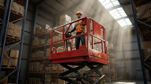
Ground conditions governed the stability envelope of every scissor lift. Engineers and safety professionals treated support reactions, centre-of-gravity location, and dynamic loads as coupled variables. On irregular terrain, small changes in slope, stiffness, or surface friction could drive large changes in tipping margin. Understanding these fundamentals allowed operators to translate manufacturer limits into practical go/no-go decisions on real sites.
Why Scissor Lifts Need Firm, Level Support
Scissor lifts relied on a narrow base width relative to their working height, which made them highly sensitive to tilt. Firm, level support kept the platform’s centre of gravity inside the support polygon defined by the wheels or outriggers. When wheels sat on soft, sloping, or fractured ground, differential settlement or sinkage shifted the centre of gravity toward an edge, reducing tipping resistance. Manufacturers and regulators therefore required operation only on compact, level surfaces unless the lift was specifically rated for inclines. Operating on grass, gravel, or unprepared fill without verification of bearing capacity and levelness significantly increased overturning risk.
Slope, Tilt Ratings, And Stability Margins
Each scissor lift carried a maximum allowable slope or tilt rating, expressed in degrees or percent gradient. This rating defined the limit at which the machine could travel or, for some models, elevate safely without exceeding its design stability margin. The value appeared in the operator’s manual, on the identification plate, or on decals at the platform controls. Exceeding the tilt rating shifted the resultant load vector outside the safe base area, which could trigger onboard tilt alarms and automatic cut-out of lift functions. Using a digital inclinometer to confirm actual slope against the rated value was essential before driving or positioning on an incline.
Soil, Grass, And Soft Ground Bearing Capacity
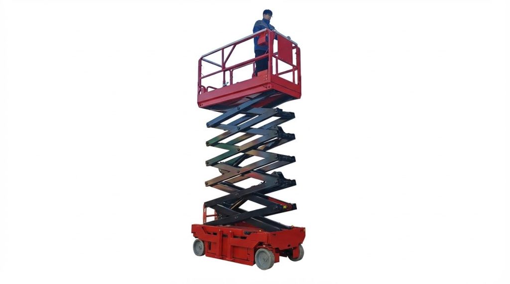
Soft ground such as grass, uncompacted soil, or gravel provided lower and less predictable bearing capacity than concrete or asphalt. High wheel or outrigger contact pressures could cause local punching or progressive sinkage, especially near trenches, backfilled services, or saturated zones. Track-driven scissor lifts reduced ground pressure by distributing load over a larger contact area, which improved performance on loose or soft surfaces. However, even tracked units still required adequate bearing capacity and level support, often verified by using hardwood mats or engineered pads to spread loads. Operators needed to treat visually “firm” grass with caution, since underlying soil moisture and compaction controlled actual support.
Wind, Weather, And Dynamic Load Effects
Wind, rain, and surface contamination acted as dynamic modifiers of stability on irregular terrain. Crosswinds generated overturning moments that combined with slope-induced tilting, which effectively reduced the allowable working height and load. Outdoor-rated lifts therefore carried reduced platform height and capacity limits to account for wind loading. Rain and mud lowered surface friction, increased stopping distances, and promoted wheel slip on slopes, making controlled travel more difficult. Sudden steering inputs, abrupt braking, or driving with the platform raised introduced additional dynamic loads that shifted the centre of gravity, so standards and manufacturer guidance required low travel speeds, straight-line movement on slopes, and lowering the platform before driving wherever practicable.
Engineering Controls For Sloped And Soft Terrain
Engineering controls determined whether a scissor lift could operate safely on sloped or soft terrain. Designers used drive systems, support structures, and sensing technologies to manage stability margins. These controls did not remove the need for level ground, but they reduced risk where limited inclines or marginal surfaces were unavoidable.
Track Drives, Tires, And Ground Pressure
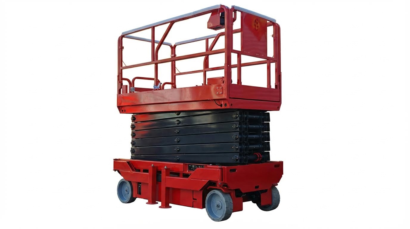
Track-driven scissor lifts distributed machine weight over a larger contact area than wheeled units. This reduced ground pressure, which improved flotation on grass, compacted soil, and loose surfaces. Engineers selected track geometry and rubber compound to balance traction, wear, and vibration. On slopes, tracks improved longitudinal grip and reduced the likelihood of localized sinkage that could induce chassis tilt. Wheeled machines relied on tire size, tread pattern, and inflation pressure to control ground pressure and traction. Solid or foam-filled tires resisted punctures but transferred higher point loads to weak soil. Operators still had to verify that measured ground bearing capacity exceeded the lift’s maximum wheel or track load, including rated platform load and dynamic factors.
Outriggers, Stabilizers, And Support Pads
Outriggers and stabilizers extended the effective base width of a scissor lift and lowered the center of rotation. When correctly deployed, they converted a mobile platform into a temporary, quasi-fixed structure with improved overturning resistance. Manufacturers specified maximum allowable slope for leveling systems and required firm, compacted support under each jack. On soft or sloping ground, operators placed hardwood mats or engineered plastic pads under outrigger feet to spread loads and maintain a level interface. Engineers sized these pads based on expected jack loads and soil bearing capacity, adding safety factors for moisture and disturbance. Procedures required that braked wheels remained in contact with the ground until outriggers fully loaded, which often meant reversing up a slope before deployment. This reduced the chance of unintended movement when the suspension unloaded.
Onboard Tilt Sensors, Alarms, And Interlocks
Modern scissor lifts integrated tilt sensors that continuously measured chassis angle relative to gravity. Control systems compared this angle with manufacturer-defined thresholds for travel and elevation. When the slope exceeded set limits, the machine generated audible and visual alarms and usually locked out lift or drive functions. This interlock strategy prevented operators from raising the platform on unsafe inclines, even if ground conditions appeared acceptable. Designers calibrated separate thresholds for longitudinal and lateral tilt, because side slopes typically reduced stability more aggressively. Periodic functional tests before work verified that alarms and cut-outs triggered at the correct angles. Maintenance teams had to protect sensors from contamination, shock, and unauthorized bypassing, since disabled or drifted sensors removed a critical layer of protection.
Digital Tools, Inclinometers, And Load Monitoring
Digital inclinometers allowed crews to quantify slope rather than estimate it visually. Operators measured gradients along both axes at the intended lift position and compared them with the scissor lift’s published slope ratings. This supported go/no-go decisions and documented compliance with site procedures. Some advanced platforms incorporated onboard displays showing live tilt and load data. Integrated load-sensing systems monitored platform mass and its distribution against rated capacity, including extension deck positions. When loads approached limits, the control system could restrict further elevation or travel. Combining external survey tools with onboard monitoring created a layered approach: survey instruments validated the work zone, while machine sensors enforced limits during operation. This integration supported predictive maintenance as well, because abnormal tilt or load patterns over time indicated worn components, uneven tire wear, or structural deformation that required inspection.
Operational Best Practices And Compliance
Operational discipline determined whether engineering safeguards actually controlled risk on irregular terrain. Best practice combined structured site assessment, conservative driving rules, formal operator competence, and data-driven maintenance. Together these measures aligned field use with manufacturer limits and regulatory expectations for mobile elevating work platforms (MEWPs).
Site Assessment And Pre-Use Inspection
Operators first evaluated the ground before moving the lift into position. They identified debris, potholes, underground services, overhead power lines, and any local soft spots or surface transitions. They measured slopes with a digital inclinometer and compared the gradient against the machine’s rated travel and elevation limits from the manual and ID plate. If the surface was grass, gravel, or fill, they assessed compaction and bearing capacity and rejected visibly unstable or waterlogged areas. Pre-use inspections then covered structure, guardrails, scissor stack, and chassis for cracks, deformation, or corrosion. Technicians checked tires or tracks, wheel nuts, brakes, hydraulic hoses, and fittings for leaks, plus battery state of charge or fuel level. They verified emergency stops, descent controls, tilt alarms, interlocks, and platform controls worked correctly, and removed the unit from service if any defect affected stability or safe function.
Driving, Positioning, And Load Management
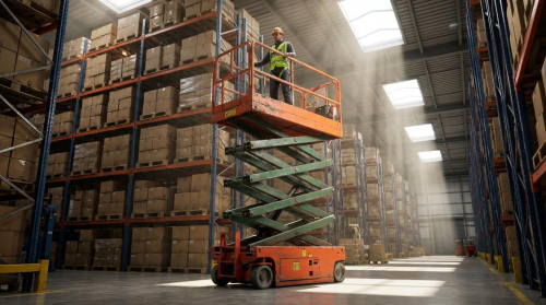
Operators kept platforms fully lowered while travelling, especially on slopes or uneven ground. They drove straight up or down gradients within rated limits, avoided cross-slope travel, and used slow speed settings in tight or low-traction areas. Sharp turns, sudden braking, or rapid acceleration were avoided because these actions shifted the centre of gravity and reduced stability margins. When outriggers or stabilizers were available, they positioned the chassis on the firmest possible ground, deployed pads or cribbing, and levelled the platform before elevation. Load management followed the manufacturer’s rated capacity, including workers, tools, and materials, with safety factors already embedded in the rating. Operators distributed mass evenly, limited use of extension decks on marginal ground, and avoided leaning or climbing on guardrails, which altered the effective load and centre of gravity. Tools and materials were secured with lanyards or storage systems to prevent dropped-object hazards on busy sites.
Training, Certification, And Safe Work Methods
Regulators typically required formal MEWP training and documented authorization from the employer. Training covered equipment classes, slope and load charts, ground condition assessment, and proper use of stabilizers, pads, and wheel chocks. It also addressed local legal requirements, such as prohibitions on travelling with the platform raised and mandatory fall protection in certain jurisdictions. Competent operators learned to interpret alarms, understand cut-out logic for tilt and overload, and follow rescue procedures for platform entrapment or power loss. Safe work method statements or job safety analyses then translated these principles into task-specific steps. These documents defined approach paths, exclusion zones, spotter duties, communication signals, and weather limits. Supervisors verified adherence in the field through observation, near-miss reporting, and periodic refresher training, which reduced normalization of deviance during repetitive tasks.
Integrating Digital Twins And Predictive Maintenance
Fleet managers increasingly used digital twins and telematics to support safe operation on irregular terrain. A digital twin mirrored each lift’s configuration, duty history, and fault data, allowing engineers to model stability margins for specific slope, load, and wind combinations. Integrated inclinometers, load cells, and duty-cycle sensors streamed operating data, which predictive algorithms used to flag unusual tilt events, overloads, or harsh driving patterns. Maintenance teams then prioritized inspections of units exposed to repeated slope operation, high vibration, or frequent tilt alarms. Predictive maintenance schedules focused on structural welds, scissor pins, bushings, hydraulic cylinders, and tire integrity, where degradation affected stability first. Over time, aggregated data informed site planning: engineers could identify problematic zones where lifts repeatedly approached tilt limits or ground conditions degraded. This feedback loop supported redesign of access routes, ground improvement, or selection of more suitable tracked or rough-terrain platforms for future work.
Summary: Risk-Controlled Use On Irregular Terrain
Risk-controlled scissor lift use on slopes, grass, and uneven ground relied on a layered approach. Engineering limits such as slope ratings, load charts, wind ratings, and ground bearing requirements defined the operating envelope. Within that envelope, operators applied structured processes for site assessment, pre-use inspection, and conservative driving and positioning. Where terrain deviated from firm, level ground, additional controls such as track drives, outriggers on adequate pads, and wheel chocks became mandatory rather than optional.
Industry guidance and rental practice converged on a clear priority hierarchy. The safest option was to avoid irregular terrain entirely and relocate the task or use alternative access equipment. When use on slopes or soft ground was unavoidable, standards and manufacturers required strict adherence to maximum gradient limits, reduced travel speed, and prohibition of elevating on non-level support unless the machine was specifically designed and configured for that case. Onboard tilt sensors and cut-out interlocks reduced but did not eliminate the need for competent judgment.
Future developments pointed toward more sensor-rich platforms, integrated load and tilt monitoring, and closer coupling with digital tools. Digital twins and predictive maintenance systems enabled better tracking of structural usage, overload events, and recurring fault patterns associated with rough-terrain deployment. These tools supported data-driven inspection intervals and fleet derating strategies for units that had operated frequently on demanding ground conditions.
From a practical standpoint, organizations needed to embed these controls into procurement, planning, and training. Procurement policies had to specify rough-terrain or tracked models where work on irregular ground was foreseeable. Method statements and permits to work had to reference measured slopes, pad design, and weather thresholds. Training and certification programs had to emphasize that interlocks were last lines of defence, not operating guides. A balanced view recognized that technology expanded the safe operating window, but long-term safety performance still depended on conservative planning, disciplined inspection, and respect for the underlying physics of stability.

