Modern automotive and industrial workshops depended on correctly specified scissor lifts and alignment racks for safe, efficient operations. Successful projects required more than buying equipment; planners had to coordinate layout, civil works, power, and safety systems as a single integrated package. This article covered how to plan workshop layouts, compare lift types, and match capacity to real duty cycles, while ensuring adequate clearances and utility integration. It then examined structural and anchoring requirements, detailed installation and commissioning practices with safety compliance, and concluded with lifecycle maintenance strategies and future trends in lift and alignment technology.
Planning Workshop Layout And Equipment Selection
Planning the workshop layout determined how effectively scissor lifts and alignment racks operated over their service life. Engineers evaluated equipment types, capacities, and spatial constraints before committing to a configuration. Good planning reduced retrofit work, minimized safety risks, and improved technician productivity. The following subsections addressed the main technical decisions during this planning phase.
Comparing Scissor Lifts And Alignment Racks
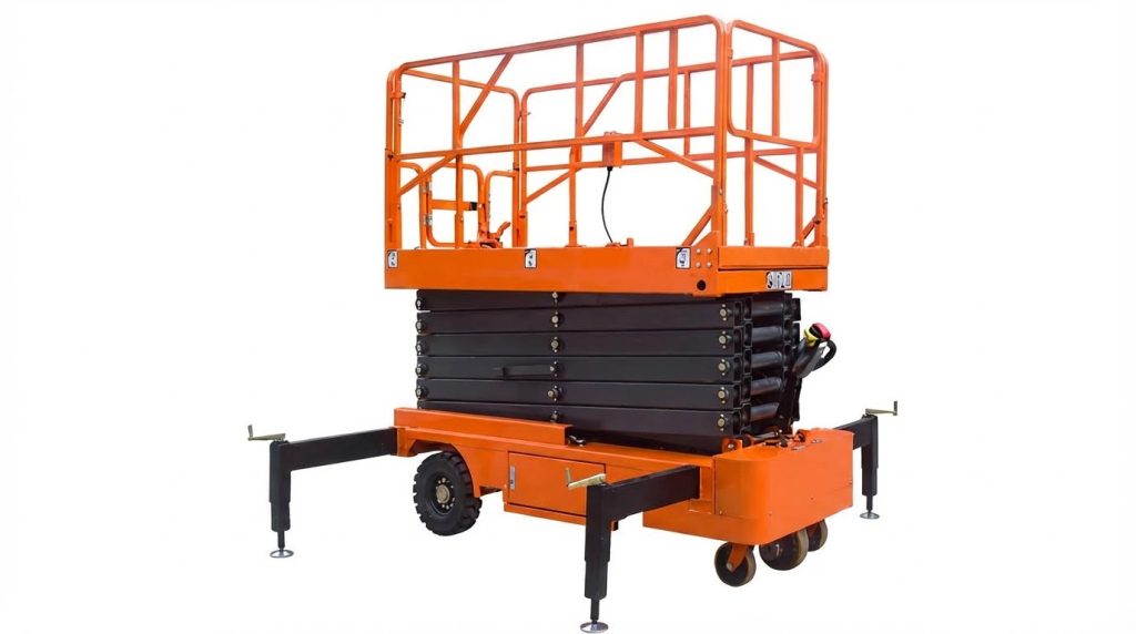
Scissor lifts and alignment racks served different primary functions in modern workshops. Scissor lifts supported general underbody service, tire work, and chassis inspection, and operators often chose them where floor space was limited because of their compact footprint and lower installed cost compared with four-post lifts. Alignment racks, by contrast, provided long, precisely leveled platforms with integrated turntables and slip plates to support accurate wheel alignment using laser or camera systems. When planners compared both options, they considered required platform length, permissible foundation loading, access for wheel alignment sensors, and compatibility with existing diagnostic equipment. In mixed-use bays, a scissor lift with alignment-capable accessories offered flexibility, but dedicated alignment racks still delivered higher repeatability for geometry measurements.
Defining Load, Duty Cycle, And Use Cases
Correct load and duty-cycle definition prevented premature structural or hydraulic failures. Engineers specified rated capacity based on the heaviest vehicle class, including accessories and potential dynamic loading during raising and lowering. Duty cycle included the number of lift cycles per shift, operating hours per day, and expected peak utilization, which influenced selection of hydraulic power unit size, motor rating, and cooling requirements. Use cases also covered service scope, such as general repair, quick tire changes, or high-precision alignment, which dictated platform length, wheelbase range, and approach ramp geometry. For workshops handling mixed fleets, planners often selected a higher capacity class and longer platforms to avoid constraints when vehicle types changed over time.
Spatial Planning, Clearance, And Traffic Flow
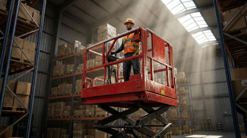
Spatial planning around the lift or rack directly affected safety and throughput. Industry practice required at least 1.6 m of clear space in front of a scissor lift platform of approximately 4.5 m length to accommodate tool trolleys, alignment heads, and technician movement. Designers provided unobstructed passages on both sides to prevent collisions during vehicle entry, exit, and lift operation, and they avoided placing columns or storage within swing envelopes of doors and steering movements. Traffic-flow planning separated pedestrian routes from vehicle paths and defined turning radii so vehicles could approach the lift in a straight line, reducing positioning time. Locating high-use bays near entrances reduced maneuvering and minimized the risk of incidents in congested zones.
Integration With Existing Utilities And Systems
Integration with existing utilities ensured reliable and compliant operation of scissor lifts and alignment racks. Designers verified that electrical supply circuits had adequate capacity, correct grounding, and appropriate overcurrent protection before connecting hydraulic power units, control cabinets, and alignment electronics. Compressed air lines, data networks, and exhaust extraction systems were routed to avoid interference with lift mechanisms, moving platforms, and safety devices, while still remaining accessible for maintenance. For in-ground scissor lifts, planners coordinated with civil and structural engineers to identify underground utilities and drainage paths before excavation, reducing the risk of service conflicts or water accumulation. Alignment racks also required stable, level foundations with compatible cable routing for sensors and cameras, so integration with building management and diagnostic systems was considered early in the layout phase.
Civil, Structural, And Anchoring Requirements
Civil and structural provisions determined whether scissor lifts and alignment racks operated safely and within design life. Workshop floors required adequate thickness, strength, and reinforcement to resist concentrated wheel and column loads without cracking. Proper pit design, drainage, and backfill preparation controlled groundwater, corrosion, and long-term settlement. Accurate leveling and anchor positioning ensured platforms remained stable, with correct geometry for lifting, alignment, and safety systems.
Floor Thickness, Concrete Grade, And Reinforcement
Workshop slabs for lift installation required verification of both thickness and compressive strength. For ultra-thin surface-mounted scissor lifts, industry practice specified at least 160 mm slab thickness with C25 or higher concrete (characteristic strength ≥25 MPa). In-ground lift pits typically used similar or higher strength concrete, combined with local thickening under high-load bearing points. Designers specified reinforcement meshes or bars to distribute wheel and column loads and to limit crack widths under cyclic loading.
Backfill or existing subgrade under the slab needed compaction to a defined density to prevent differential settlement. Engineers often specified welded wire mesh in the top third of the slab and additional bars around anchor zones to resist pull-out forces. For alignment racks, long wheel tracks introduced bending and torsion into the slab, so continuous reinforcement along rack lines improved stiffness and alignment stability. Compliance with local concrete and structural design codes, such as Eurocode 2 or ACI 318, helped ensure adequate safety margins.
Pit Design For In-Ground Scissor Lifts
In-ground scissor lifts required carefully dimensioned pits to accommodate the lift envelope, maintenance access, and drainage. Typical pit depths were about 360 mm, and deviations from this depth could reduce stability or increase construction cost. Designers cast side walls and pit bottoms with approximately 150 mm thick concrete, using C25 or higher grade to handle bearing and lateral pressures. Reinforcement in walls and bases controlled cracking from restraint, temperature gradients, and hydraulic reactions.
Clearances around the lift structure allowed for installation tolerances, hydraulic line routing, and inspection access. Edge details required chamfers or steel angles where vehicles rolled across to reduce spalling at slab edges. Pit bases had to be flat and level within tight tolerances to prevent twist in the scissor mechanism. Where groundwater existed, engineers considered waterproofing membranes, drainage sumps, and possibly uplift checks to prevent flotation of the pit structure.
Leveling, Surface Tolerance, And Anchor Layout
Lift and alignment rack performance depended heavily on floor flatness and level. Foundations for scissor lifts typically required surface tolerance within ±3 mm over the footprint, verified with a laser level. Excess slope or unevenness introduced tilt, unbalanced loading, and inaccurate wheel alignment readings. Installers corrected minor irregularities with non-shrink grout under baseplates or leveling shims under rack columns.
Anchor bolt layout followed the manufacturer’s installation drawings with strict positional accuracy. Embedded anchors or sleeves had to be set before concrete placement, then re-checked for coordinates and elevation to avoid misalignment. For post-installed anchors, drilling occurred only after concrete reached specified strength, and installers used qualified mechanical or chemical anchors with documented load ratings. Anchoring patterns considered shear, tension, and fatigue loads from repeated lifting cycles and vehicle movements. Proper torqueing of fasteners and reinspection after initial load tests reduced the risk of loosening in service.
Managing Drainage, Backfill, And Settlement Risk
Drainage design around pits and floor-mounted lifts reduced corrosion, slip hazards, and structural deterioration. In-ground scissor lift pits typically incorporated a 2%–3% slope towards a drain point or sump to prevent standing water. Designers detailed drain connections to the workshop’s wastewater system or to an oil separator if contamination risks existed. Surface-mounted lifts benefited from surrounding floor slopes that directed wash water away from anchor lines and control cabinets.
Backfill and surrounding soil conditions strongly influenced long-term settlement behaviour. Installers compacted backfill in layers to specified density and, where necessary, reinforced it with steel mesh or geogrid to stabilize soft ground. Under-slab vapor barriers and capillary breaks helped manage moisture migration that could weaken subgrades. Periodic visual checks for floor cracking, joint opening, or lift misleveling allowed early detection of settlement issues. Where significant movement occurred, engineers assessed whether slab underpinning, crack repair, or partial reconstruction was required to restore structural reliability.
Installation, Commissioning, And Safety Compliance
Decommissioning Existing Lifts And Site Preparation
Decommissioning started with isolating all energy sources to the existing lift or rack. Technicians locked out and tagged out electrical, hydraulic, and pneumatic supplies according to company procedures and local regulations. They then discharged stored hydraulic pressure and bled residual energy from accumulators or hoses. Used oils, contaminated absorbents, and worn components required disposal following hazardous waste rules and manufacturer guidance.
After removal of legacy equipment, the team inspected the slab for cracking, delamination, or chemical attack. Any anchor holes or damaged areas were cleaned, doweled if required, and patched with structural repair mortar compatible with the existing concrete. For in‑ground scissor lifts, surveyors checked for underground utilities and verified pit location against architectural and structural drawings. The work area was then cordoned off, cleared of debris, and laid out with reference lines for the new lift or alignment rack envelope, including safety clearances and access paths.
Mechanical, Hydraulic, And Electrical Installation
Mechanical installation began with positioning the scissor lift or alignment rack on the prepared foundation or pit. Installers used laser levels and shims to achieve the specified flatness and level before torqueing anchor bolts to the manufacturer’s values. They verified that embedded plates and anchors matched the equipment drawings to avoid frame distortion during tightening. Moving components such as scissor arms, platforms, and sliding runways were checked for free travel and correct clearances.
Hydraulic circuits were then connected using rated hoses, fittings, and shutoff valves. Technicians routed hoses to avoid pinch points and abrasion, secured them with clamps, and confirmed pressure ratings exceeded system maximums with a safety margin. They filled the reservoir with the specified hydraulic fluid, bled air from cylinders, and inspected all joints for seepage under low‑pressure pretests. Electrical work included connecting motors, control panels, and safety circuits to a dedicated, grounded supply sized for the full load current.
Electricians verified phase sequence, protective earth continuity, and correct operation of disconnect switches and overcurrent protection. Control wiring for limit switches, emergency stops, interlocks, and alarms was terminated according to schematics, with ferruled conductors and labeled terminals. Before energizing, they performed insulation resistance tests and functional checks on relays and contactors. Only after mechanical guards were in place and all covers closed did they apply power and execute initial motion tests at reduced speed.
Alignment Rack Leveling And Accuracy Controls
Alignment racks required tighter geometric tolerances than general service lifts. Installers first leveled the main runways using precision spirit levels or electronic inclinometers, working both longitudinally and transversely. They adjusted leveling pads or shims until the surface tolerance stayed within approximately ±3 mm over the full platform length, as recommended for accurate wheel alignment. Cross‑beam heights and front‑to‑rear symmetry were checked to prevent measurement bias.
Turntable pockets and slip plates were then set flush with the runways and aligned to the rack centerline. Technicians verified that the rack sat on a level slab, free from twist, by cross‑measuring diagonals and checking reference points with a laser level. Integrated alignment sensors, laser heads, or camera targets were mounted according to the manufacturer’s instructions, with attention to mounting stiffness and repeatable positioning. The system was then calibrated using supplied fixtures or calibration wheels, and the results were compared to baseline values.
Operational checks included rolling a vehicle onto the rack, engaging wheel chocks, and locking the rack at the working height. The team verified that measured caster, camber, and toe values remained stable when raising, lowering, and locking the rack. Any drift indicated residual level errors, loose fasteners, or sensor misalignment, which required correction before the rack entered service. Documentation of the final leveling data and calibration certificates supported workshop quality systems and audits.
Load Testing, Safety Devices, And Standards
Commissioning concluded with structured load testing and verification of safety functions. Technicians first performed no‑load cycling to confirm smooth motion, correct stopping points, and proper operation of limit switches. They then applied test loads up to the rated capacity, typically using vehicles, test weights, or a combination, while monitoring for abnormal noise, excessive deflection, or hydraulic instability. During full‑load holds, they checked the foundation for cracking, settlement, or anchor movement.
All safety devices required functional testing, including mechanical locks, safety latches, velocity fuses, and emergency lowering systems. Operators actuated emergency stop buttons, backup alarms, horns, and warning lights to confirm reliable response. They validated that interlocks prevented lift operation when platforms were not in the locked position or when safety bars were engaged. For alignment racks, they confirmed that locking mechanisms maintained geometry under load without measurable shift.
Installers referenced applicable standards and regulations, such as EN 1493 or ANSI/ALI guidelines for vehicle lifts, and local electrical and occupational safety codes. They ensured rated load markings, warning labels, and instruction placards were visible and legible on the equipment. Final documentation included test records, torque logs, electrical test reports, and maintenance instructions. The workshop then trained operators on safe use, daily inspections, and emergency procedures before releasing the lift or rack for routine service work.
Summary, Lifecycle Performance, And Future Trends
Scissor lift and alignment rack installations in modern workshops required careful coordination between layout planning, civil works, and mechanical and electrical integration. Successful projects respected concrete thickness, reinforcement, and surface tolerances, then combined precise anchoring with robust hydraulic and electrical connections. Commissioning processes validated load capacity, safety devices, and alignment accuracy before the equipment entered regular service. Workshops that followed structured procedures during planning and installation typically achieved higher uptime and fewer structural or operational defects.
Lifecycle performance depended heavily on disciplined inspection and maintenance regimes. Daily checks of hydraulics, structures, tires or tracks, and safety controls, combined with weekly lubrication and periodic fluid changes, significantly reduced unplanned downtime. Alignment racks that remained level, clean, and correctly anchored maintained measurement accuracy over longer intervals. Annual inspections by qualified technicians, supported by documented test results and load tests, helped detect early-stage fatigue, settlement, or control issues before they affected safety.
Future workshop designs increasingly integrated scissor lifts and alignment racks into digital maintenance ecosystems. Trends included sensor-based condition monitoring, remote diagnostics, and automated logging of lift cycles and overload events to optimize maintenance intervals. Energy-efficient power units and improved hydraulic sealing technologies aimed to reduce leakage and environmental impact. In practice, workshop managers would balance capital cost, structural upgrades, and digital features against expected duty cycles and service mix. A measured approach that combined conservative structural design, standards-compliant installation, and data-driven maintenance would keep these lifting and alignment systems reliable as vehicle platforms and regulatory expectations continued to evolve.

