Scissor lift battery systems determined duty cycle, safety margin, and overall fleet availability. The complete workflow covered chemistry selection, safe removal of existing packs, correct installation and wiring, and final commissioning with appropriate chargers. Each step required disciplined safety controls, correct terminal sequencing, and proper series or parallel configuration for 24–48 V architectures. This article outlined practical, field-proven methods that aligned with regulatory expectations while supporting long-term reliability and simplified maintenance across mixed fleets.
Battery Types, Duty Cycles, And Selection Criteria
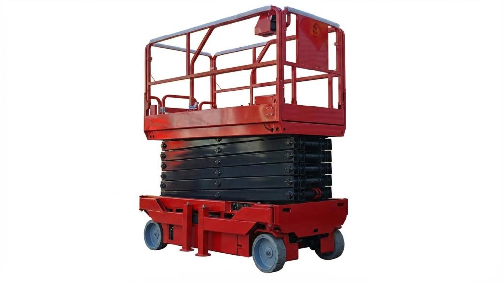
Scissor lifts used electric deep-cycle batteries to deliver sustained current over long duty cycles. Engineers matched battery chemistry and capacity to lift height, platform load, and expected shift duration. Incorrect selection reduced runtime, accelerated sulfation, and increased unplanned outages. A structured comparison of chemistries, voltage, and amp-hour (Ah) ratings supported reliable fleet operation and predictable maintenance planning.
Deep-Cycle Chemistries For Scissor Lifts
Scissor lifts primarily used deep-cycle lead-acid batteries because they tolerated repeated discharge and recharge cycles. Flooded lead-acid cells required periodic watering and electrolyte level checks to keep plates covered and prevent sulfation. Sealed lead-acid variants, including AGM and gel, eliminated watering but still needed regular terminal inspection and cleaning. Lithium-ion packs provided high cycle life, fast charging, and stable voltage under load, which suited intensive rental or multi-shift duty cycles, but required compatible chargers and higher capital cost.
Deep-cycle batteries differed from automotive starting batteries, which delivered short, high-current bursts instead of sustained discharge. For lifts, designers prioritized cycle life at 50–80 % depth of discharge, not cold-cranking amps. Proper chemistry selection considered ambient temperature, charging infrastructure, and whether the lift operated indoors where vented hydrogen from flooded cells required ventilation. These factors determined both safety controls and lifecycle performance.
Sizing Voltage And Amp-Hours To The Application
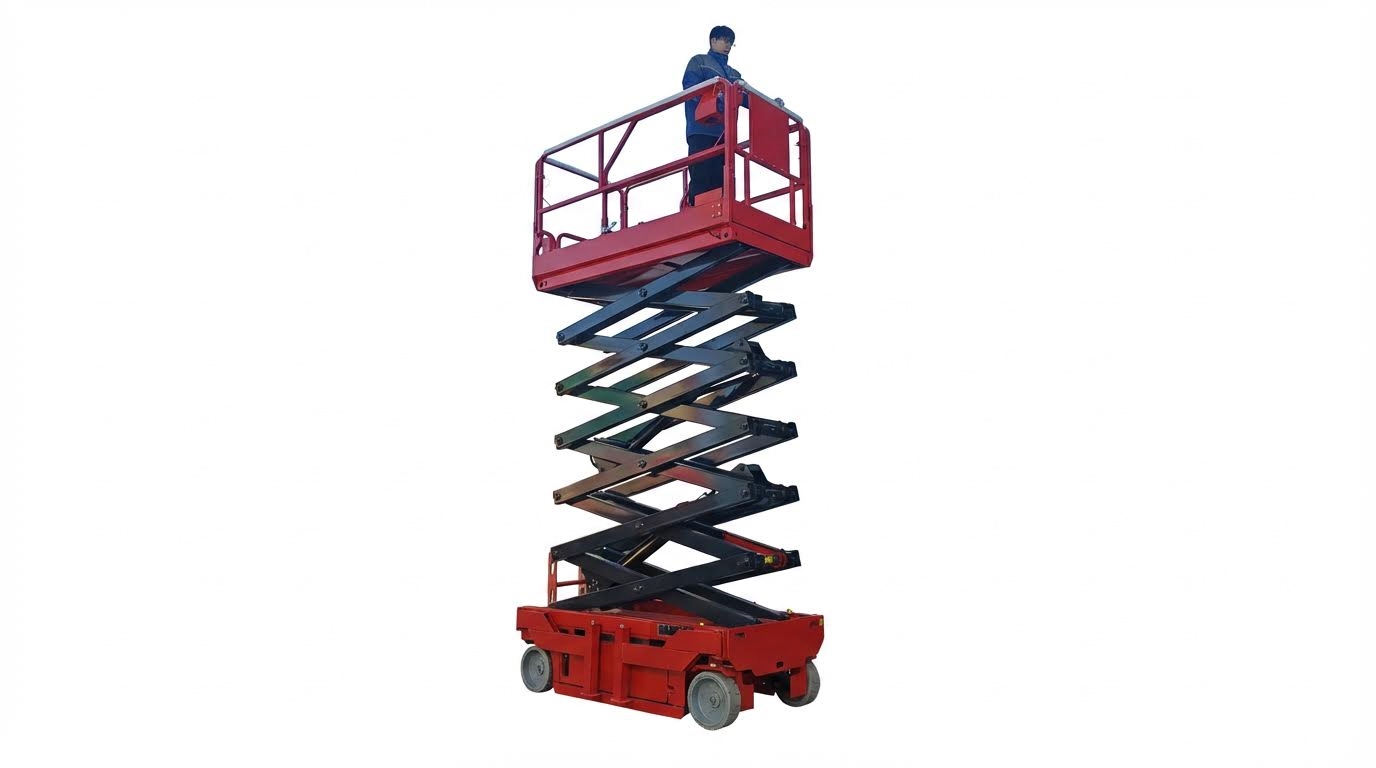
Most electric scissor lifts operated on system voltages between 24 V and 48 V, assembled from series-connected batteries. Higher system voltage reduced current for the same power, which lowered cable I²R losses and allowed smaller conductors. Manufacturers specified the nominal pack voltage in the service manual, and replacement configurations had to match that rating. Deviating from the designed voltage risked controller faults, reduced performance, or damage to drive and lift motors.
Amp-hour capacity defined expected runtime for a given duty cycle. Engineers selected Ah ratings based on average platform load, drive usage, lift frequency, and required operating hours between charges. Higher Ah extended runtime but increased battery mass, which affected transport weight and sometimes floor loading limits. For rental fleets, standardizing on a capacity that supported a full typical shift without deep discharges below about 80 % depth of discharge improved battery life. Duty-cycle profiling with logged current draw data allowed more accurate sizing than nameplate estimates alone.
Lead-Acid Vs. AGM, Gel, And Lithium-Ion Options
Flooded lead-acid batteries offered the lowest acquisition cost but required regular maintenance, including electrolyte checks, watering, and corrosion control. They vented gas during charging, so operators needed adequate ventilation and ignition control around charging areas. AGM batteries immobilized the electrolyte in glass mat separators, improving vibration resistance and allowing higher discharge rates. AGM also tolerated wider temperature swings better than gel cells, which preferred moderate temperatures and lower discharge currents.
Gel batteries used a silica-thickened electrolyte and delivered slower discharge characteristics suited to lighter, steady loads and longer standby periods. They resisted deep discharge damage somewhat better than standard flooded cells but required chargers with correct voltage limits to avoid gas pockets. Lithium-ion solutions, including LiFePO₄, reduced pack weight, shortened charge times, and delivered more consistent voltage across the lift height. Their higher energy throughput per life cycle often offset initial cost in high-utilization fleets, provided that chargers, battery management systems, and safety certifications matched the lift design.
Lifecycle Cost, Warranty, And Fleet Standardization
Battery selection for scissor lifts benefited from lifecycle cost analysis rather than purchase price alone. Engineers compared total kilowatt-hours delivered over the battery’s life, maintenance labor, water consumption, and downtime costs due to premature failure. Lead-acid packs typically had lower upfront cost but higher service labor and shorter cycle life, especially under repeated deep discharges. Lithium-ion and high-quality AGM options carried longer warranties and higher usable cycle counts, which could reduce cost per operating hour in intensive applications.
Warranty terms needed alignment with real duty cycles, including average depth of discharge, ambient temperature, and charging regime. Overstressing batteries outside published limits often voided coverage, so documenting operating conditions was important. Fleet standardization on a limited number of chemistries and capacities simplified training, spare inventory, and charger management. Standard connector types, voltage levels, and charger algorithms reduced wiring errors and improved safety. A consistent battery platform across models also enabled rotation strategies and easier compliance with local recycling regulations for spent lead-acid or lithium-ion packs.
Safe Removal Of Existing Scissor Lift Batteries
Safe removal of scissor lift batteries protected technicians, equipment, and nearby personnel. The process combined electrical isolation, chemical hazard control, and proper material handling. Each step reduced the risk of arc flash, acid exposure, musculoskeletal injury, and unplanned machine movement. The following subsections described a structured approach suitable for rental fleets, construction sites, and in-plant maintenance teams.
Lockout, PPE, And Hazard Controls
Technicians first placed the lift in a safe state before touching the battery circuit. They parked on a level surface, lowered the platform fully, turned the key off, and removed it to prevent activation. They disconnected the machine from any external charger or shore power to eliminate backfeed into the DC bus. Lockout/tagout procedures then controlled energy sources according to site rules and applicable standards such as OSHA 29 CFR 1910.147.
Personal protective equipment addressed both electrical and chemical hazards. At minimum, workers wore safety glasses or goggles and acid-resistant gloves to prevent eye and skin contact with electrolyte. Where local risk assessments required it, they added face shields, long sleeves, and chemical aprons, especially around flooded lead-acid batteries. Adequate ventilation prevented accumulation of hydrogen gas from charging batteries, and personnel banned smoking, grinding, and open flames near the work area.
Battery Access, Handling, And Weight Management
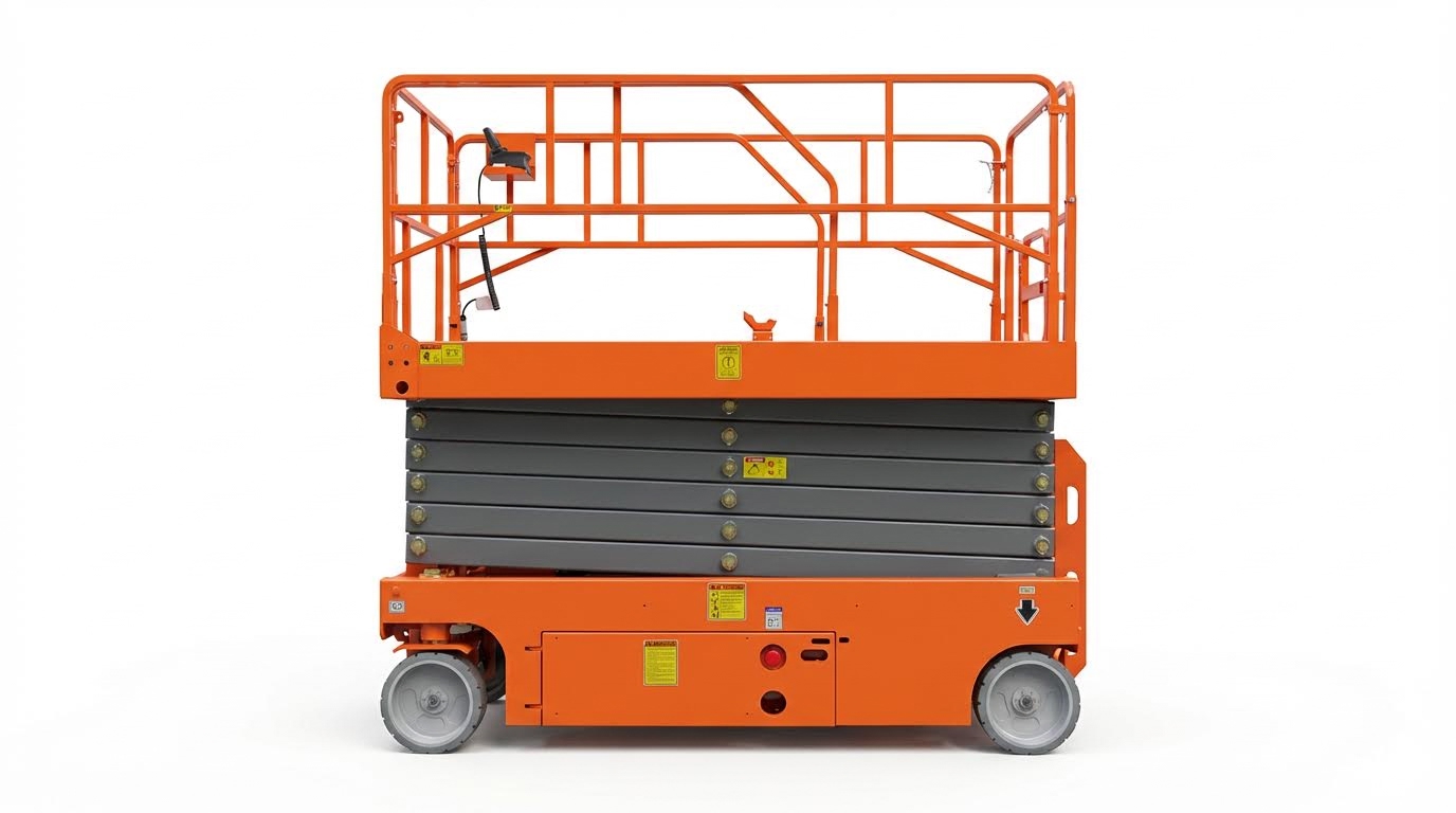
Battery access points varied by scissor lift model, so technicians verified locations in the operator or service manual. Packs were typically located in a side drawer, rear compartment, or under-deck tray beneath the platform. Before opening access panels, they ensured panels were supported and could not drop or pinch cables. They visually inspected the compartment for damaged insulation, cracked cases, or leaked electrolyte before handling batteries.
Individual deep-cycle batteries used on electric scissor lifts often weighed 25–40 kg, and full packs weighed significantly more. To control ergonomic risk, technicians used battery lifting straps, built-in slide-out trays, or mechanical aids such as hoists where available. For heavier industrial units, a second person assisted to maintain stable lifting posture and avoid sudden twisting. They kept batteries upright to prevent electrolyte spillage and avoided placing them on uneven or conductive surfaces.
Correct Terminal Disconnection Order And Tools
Correct terminal disconnection order minimized short-circuit and arcing risk. Technicians always verified the lift was off and unplugged from the charger before touching conductors. They then disconnected the negative (−) battery cable first, which reduced the chance of completing a circuit if a tool bridged the positive terminal to chassis. After isolating the negative side, they removed the positive (+) cables and any intercell jumpers as needed.
Insulated hand tools or tools with intact handles reduced accidental contact with live parts. A correctly sized wrench or socket prevented slipping on terminal hardware and reduced mechanical damage to posts. Workers avoided placing metal tools or hardware on top of batteries, where they could bridge terminals. As they removed cables, they labeled and staged them to preserve polarity and series or parallel configuration for later installation.
Cleaning Trays, Cables, And Corrosion Mitigation
After battery removal, technicians cleaned the compartment to restore reliable contact surfaces. They neutralized any acid residue on trays using a mild alkaline solution such as baking soda and water, taking care not to introduce liquid into battery cells. They removed loose rust, dirt, and debris that could trap moisture or abrade insulation. Thorough drying of the tray and surrounding structure prevented future corrosion and tracking paths.
Battery cables and lugs also required inspection and cleaning before reuse. Corroded terminals were brushed with a dedicated terminal brush or wire brush until bright metal appeared, then wiped clean. Damaged insulation, cracked lugs, or overheated connectors triggered replacement rather than reuse to maintain current-carrying capacity. Finally, technicians planned to apply an approved terminal grease or protective spray during reinstallation to slow future corrosion and maintain low-resistance connections.
Installing, Wiring, And Commissioning New Batteries
Battery Positioning, Restraints, And Cable Routing
Install the replacement batteries only after verifying the model, voltage, and capacity against the scissor lift manual. Lower the platform, park on level ground, and ensure the key remained removed before work. Place each battery flat on the tray with the case fully supported and posts oriented to match the original layout. Maintain clearance between cases and metal structure to avoid chafing and unintended grounding.
Reinstall any factory hold-downs, brackets, or straps and tighten them so the batteries cannot move during transport. Do not overtighten plastic cases; compressing the case could cause cracks over time. Route cables along the original harness paths, avoiding sharp edges, pinch points, and moving components such as steering linkages. Use abrasion-resistant loom, grommets, and non-conductive clamps or ties to secure cables at regular intervals.
Maintain gentle bend radii in cables to prevent conductor fatigue and resistance increase. Keep low-voltage control wiring separated from high-current battery cables where possible to reduce electrical noise. Arrange cables so that service technicians can access caps, vent plugs, and inspection labels without disconnecting the pack. Verify that no cable or connector sits higher than the compartment design envelope, which could interfere with covers or platforms.
Terminal Connection Sequence And Torque Practices
Remove any temporary terminal covers only when ready to connect, keeping tools insulated and clear of parallel conductive paths. Always connect the positive (+) terminals first, then the negative (−) terminals, reversing the removal sequence used for the old pack. This practice reduced the risk of accidental short circuits to the chassis while a tool bridged the terminal and ground. Tighten terminals with a calibrated wrench or torque-limiting tool when the manufacturer specified values.
Follow torque recommendations from the lift or battery documentation; typical values for M8 studs were in the 10–15 N·m range, but references varied. Under-torqued connections increased contact resistance, causing voltage drop, heat, and accelerated terminal corrosion. Over-torqued connections could strip studs, crack lead posts, or damage threaded inserts, leading to intermittent faults. After tightening, apply an approved dielectric grease or anti-corrosion spray around, not between, the contact surfaces.
Verify that each cable lug sat flat on the terminal with full contact area and no trapped insulation. Avoid stacking excessive lugs on a single stud; use proper bus bars or distribution blocks if the design required multiple take-offs. Ensure that exposed conductive surfaces were minimized using boots, caps, or molded covers, especially near metal structure. Perform a final visual check for crossed polarity, loose hardware, and tools remaining in the compartment before energizing the system.
Parallel And Series Wiring For 24–48 V Systems
Scissor lifts typically used 24 V, 36 V, or 48 V packs built from 6 V, 8 V, or 12 V deep-cycle batteries. Series connections increased system voltage by linking the positive of one battery to the negative of the next in a chain. For example, four 6 V batteries in series produced a nominal 24 V pack, while eight 6 V units in series produced 48 V. Always confirm the intended configuration from the wiring diagram on the lift or in the service manual.
Parallel connections kept voltage constant while increasing amp-hour capacity by joining positives together and negatives together. Parallel strings had to use identical batteries of the same age, chemistry, and capacity to avoid imbalance. In mixed series-parallel packs, complete one series string first, then parallel whole strings using equal-length cables and symmetrical routing. This symmetry helped equalize resistance and current sharing between strings under both charge and discharge.
Mark each cable before removal to replicate the original topology and reduce wiring errors. Use color coding or clear labeling for positive and negative conductors to avoid reverse polarity, which could damage controllers or chargers instantly. Never create unintended loops or double connections that bypass safety devices or fuses. After wiring, measure pack voltage with a multimeter and compare it to the expected nominal value before connecting to the machine harness.
Functional Testing, Chargers, And Boosting Protocols
After wiring, visually inspect all batteries, cables, and restraints, then close covers loosely to simulate normal airflow without fully latching. Turn the key switch to the “on” position and observe the battery indicator, control panel, and any fault lights. Operate lift and drive functions at low speeds to confirm smooth motion and absence of voltage sag alarms. Listen and feel for contactor chatter or sluggish response, which could indicate poor connections or inadequate capacity.
Connect the charger specified for the lift’s battery chemistry and voltage, verifying the charge curve matches flooded, AGM, gel, or lithium-ion as installed. Incorrect charger profiles in the past led to chronic undercharge, overcharge, or thermal stress, reducing service life. Check that the charger output voltage and current fell within the manufacturer’s limits and that cables and connectors stayed cool during the initial charge. Record initial charge duration and pack voltage as a baseline for future maintenance.
When using a booster or auxiliary battery source to start auxiliary systems, follow established jump-start protocols. Connect the positive (+) booster cable to the positive posts of both the booster and disabled pack, then connect the negative (−) cable to the booster’s negative and a suitable chassis ground on the lift, away from the battery compartment. After the system started and stabilized, remove booster leads in reverse order to avoid arcing near the batteries. Do not use boosting to mask defective batteries; schedule replacement or further diagnostics if repeated boosts became necessary.
Summary And Key Safety And Reliability Takeaways
Battery replacement and wiring on scissor lifts required disciplined procedures to control electrical and chemical hazards. Technicians minimized risk by enforcing lockout, removing keys, and disconnecting external chargers before touching any conductors. Consistent use of PPE, including gloves and eye protection, reduced exposure to acid, corrosion products, and explosive gases, while correct terminal order prevented short circuits.
Safe removal practices focused on controlled access to the battery compartment, proper lifting technique, and use of straps or team lifts for heavy units. Cleaning trays and terminals with appropriate solutions restored low-resistance contact surfaces and slowed future corrosion. Technicians followed a strict sequence when reconnecting batteries, connecting positive first and negative last, and then verifying mechanical security and insulation of all conductors.
Reliability depended on correct battery selection, correct system voltage, and adequate amp-hour capacity for duty cycle and height requirements. Matching replacement batteries to the manufacturer’s specifications, using correct series or parallel wiring, and observing specified torque on terminals reduced heat, voltage drop, and nuisance failures. Regular inspection, cleaning, and electrolyte maintenance extended service life for flooded lead-acid batteries, while sealed and lithium chemistries reduced routine maintenance at higher initial cost.
From an industry perspective, fleets increasingly evaluated lifecycle cost instead of purchase price alone, which favored standardized chemistries and, in some cases, lithium-ion for high-utilization lifts. Future trends pointed toward smarter chargers, integrated battery monitoring, and tighter recycling compliance for lead-acid waste. In practice, organizations that documented procedures, trained qualified personnel, and enforced recycling and booster-use protocols achieved higher uptime, fewer incidents, and more predictable energy costs across their scissor lift fleets.

