Electric forklift hydraulics and transmissions formed the backbone of modern material-handling performance before 2026. Their design defined lifting capacity, controllability, and energy efficiency, while diagnostic practices determined uptime and safety. This article outlined core hydraulic architecture, systematic troubleshooting of hydraulic circuits, and the structure and failure modes of electric forklift transmissions and drive systems. It also summarized best-practice maintenance strategies and emerging trends in monitoring and control that shaped the evolution of these critical industrial systems.
Core Design Of Electric Forklift Hydraulic Systems
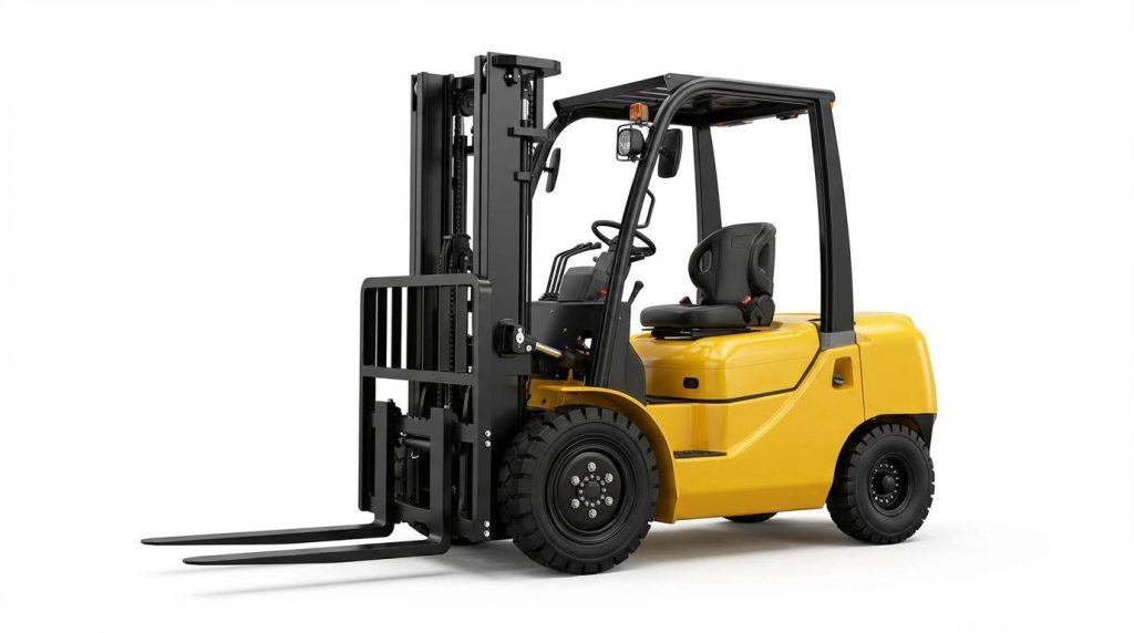
Electric forklift hydraulic systems converted electrical energy into controlled hydraulic power for lifting, tilting, and auxiliary functions. Their design balanced compact packaging, high reliability, and precise controllability under varying industrial duty cycles. Engineers configured tanks, pumps, valves, and actuators as an integrated circuit, optimized for low noise and minimal energy loss. Proper design directly affected lifting performance, component life, and safety compliance.
Key Hydraulic Components And Functions
The hydraulic tank stored working fluid and provided deaeration volume, usually with baffles and a breather filter. An electric motor drove the hydraulic pump, which generated flow and pressure for lift, tilt, and auxiliary circuits. Control valves, often monoblock or sectional, routed fluid to lift cylinders and other actuators, enabling proportional or on/off control. Hoses, pipelines, and fittings connected these elements, while filters removed contaminants to prevent wear and valve sticking. Relief valves limited maximum system pressure and protected hoses, cylinders, and the pump from overload. Throttle or speed-control valves regulated fork lowering speed and ensured smooth, predictable motion under varying loads.
Pressure, Flow, And Load Handling Basics
System pressure determined the maximum load the forklift could lift, based on cylinder bore area and mechanical leverage. Flow rate from the pump governed lifting and tilting speed, so designers sized pumps to meet required cycle times without overheating. Under heavy loads, pressure approached the relief valve setting, and any additional demand opened the relief, converting excess energy into heat. Engineers selected cylinder diameters and mast geometry to achieve rated capacity at the specified load center, typically 500 mm. They also accounted for dynamic factors such as acceleration, deceleration, and mast deflection to avoid instability. Matching motor power to peak hydraulic demand prevented voltage sag and motor overheating in electric trucks.
Fluid Selection, Filtration, And Cleanliness
Hydraulic fluid acted as power transmission medium, lubricant, and coolant, so its viscosity and additive package were critical. Designers specified ISO VG grades that maintained acceptable viscosity across the expected 70–95 °C operating range. Filtration strategies typically included a suction strainer and a return-line or pressure-line filter with defined β-ratings. Contamination control targeted particles, water, and air, because over 80% of lift failures historically traced to dirty or degraded fluid. Engineers set cleanliness classes according to component sensitivity, often using ISO 4406 codes as a reference. They also provided drain and sampling points to enable oil analysis and scheduled fluid replacement. Proper filtration design reduced valve sticking, pump wear, and seal damage, extending overhaul intervals.
Safety Margins, Relief Settings, And Compliance
Relief valves established the maximum working pressure and built-in safety margin of the hydraulic circuit. Engineers set these valves above normal working pressure yet below the structural limits of cylinders, hoses, and mast components. Descent control valves and load-holding features limited fork lowering speed and prevented uncontrolled fork drift under load. Designs followed applicable standards for industrial trucks, which addressed lifting stability, hydraulic integrity, and protection against hose or component failure. Safety factors in hose burst pressure, cylinder buckling, and mounting hardware ensured durability under shock loads and misuse. Proper calibration of relief and speed-control valves also reduced thermal loading by minimizing unnecessary bypass flow. Together, these measures supported regulatory compliance and reduced the risk of hydraulic-related incidents.
Diagnostics And Troubleshooting Of Hydraulic Circuits
Effective diagnostics of electric forklift hydraulic circuits relied on a structured, repeatable workflow. Technicians started with low-risk external checks, then progressed to targeted electrical and hydraulic measurements. This approach reduced unnecessary component replacement and minimized downtime.
Systematic Checks: Power, Fluid, And Visual Inspection
Diagnostics always began with basic power verification. Technicians confirmed battery state-of-charge, cable integrity, and fuse continuity for the pump motor circuit using a multimeter. A weak battery or high contact resistance caused slow lift, motor stalling, or intermittent pump operation.
They then checked hydraulic fluid level and condition with the dipstick or sight glass. Low level induced cavitation, pump noise, and reduced lifting pressure, while dark, milky, or burnt-smelling oil indicated contamination, oxidation, or water ingress. Corrective actions included refilling with OEM-specified fluid, flushing the circuit, and replacing filters per the duty-hour schedule.
Visual inspection focused on leaks, hose damage, and abnormal heating. Technicians inspected hoses near fittings for bulging, cracks, or wet spots, and wiped suspect areas clean to confirm active leaks. They also checked mast cylinders, control valves, and the tank area for oil streaks, loose fasteners, and damaged paint from hot oil. This initial step often isolated simple faults such as loose fittings or clogged breathers before deeper teardown.
Pump, Motor, And Valve Fault Identification
When the motor failed to start, technicians verified that the controller output delivered the correct voltage at the motor terminals during a lift command. If voltage was present but the motor did not rotate or overheated quickly, they suspected worn bearings, shorted windings, or mechanical seizure and tested the motor off-load. Abnormal whining, pulsation, or rapid temperature rise under load suggested overload from a failing pump.
Slow lifting with a correctly running motor pointed toward hydraulic-side restrictions or internal pump wear. Pressure tests at the main line compared measured pressure and flow to specification. Low pressure with normal motor speed often indicated worn gear or vane elements, internal leakage, or severe filter blockage; technicians then replaced filters, inspected suction lines for air leaks, and evaluated pump clearances.
Valve diagnostics addressed non-lifting, uncontrolled descent, or erratic speed. For non-lift, they checked solenoid coils for correct resistance, supply voltage, and response, then inspected spools for contamination or sticking. Fork drift or spontaneous lowering under load indicated internal leakage across the lowering or check valves or across cylinder seals. Relief valves set too low or leaking caused low maximum pressure; technicians used calibrated gauges to adjust to the manufacturer’s specified relief setting while respecting regulatory safety margins.
Cylinder, Hose, And Seal Leak Detection
Cylinder and hose assessments focused on both external and internal leakage. External leaks appeared as oil on rod surfaces, end caps, or along hose sheathing; persistent wetness after cleaning suggested worn rod seals, damaged tubes, or cracked fittings. Technicians disassembled affected cylinders, inspected rod chrome for pitting or scoring, and replaced seals with correct material and hardness ratings.
Internal leakage manifested as fork drift without visible oil loss or as jerky motion despite stable pump pressure. To confirm, technicians pressurized the circuit, then isolated cylinders and monitored drift or pressure decay over a defined time interval. Excessive decay indicated bypass across piston seals or valve seats. They also checked for air ingress, which produced foaming, spongy response, and gurgling noises; bleeding procedures and suction-side seal replacement restored solid hydraulic columns.
Leak location methods combined visual inspection, cleaning, and non-contact tests. Technicians used cardboard or paper near suspected points rather than hands to avoid high-pressure injection injuries. In critical cases, they applied fluorescent dye and UV lamps or performed static pressure tests with calibrated gauges. Throughout, they maintained strict cleanliness to prevent introducing new contaminants while repairing leak sources.
Predictive Maintenance And Digital Monitoring
Predictive strategies used operating data to detect hydraulic degradation before functional failures occurred. Electric forklifts with integrated controllers and telematics logged lift cycles, pump run time, peak pressures, and oil temperature histories. Analysts trended this data to identify gradual increases in lift time, energy consumption, or maximum temperature, which indicated growing internal leakage, pump wear, or cooling deficiencies.
Condition-based maintenance combined scheduled fluid and filter changes with targeted inspections triggered by thresholds. For example, repeated operation above 95 °C oil temperature, or frequent pressure relief events, prompted checks on cooling circuits, relief valve settings, and duty profiles. Some fleets used oil sampling programs, measuring particle counts, water content, and additive depletion to
Electric Forklift Transmission And Drive Systems
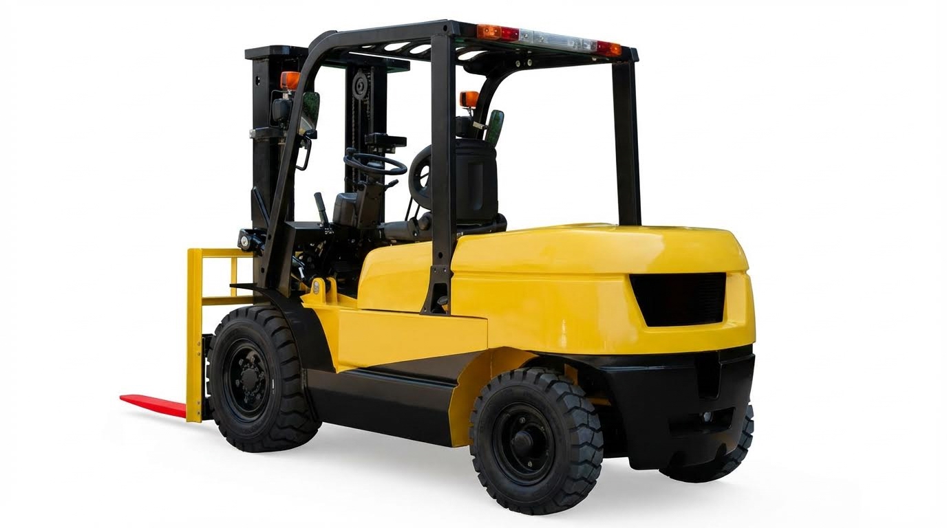
Electric forklift transmission and drive systems converted motor torque into controlled wheel motion and travel speed. These systems interacted closely with hydraulic circuits, especially where hydraulic transmissions or torque converters supported drive or auxiliary functions. Robust design, correct oil management, and structured diagnostics reduced downtime and protected safety. The following subsections focused on architecture, typical failure modes, lubrication and cooling strategies, and integration with modern control and telematics platforms.
Transmission Types, Torque Converters, And Clutches
Electric forklifts used several transmission architectures depending on capacity and duty cycle. Low to medium capacity trucks frequently used electric drive axles with reduction gear sets and wet disc brakes, without a hydraulic torque converter. Higher capacity or hybrid configurations sometimes retained hydraulic transmissions with torque converters and multi-plate clutches, similar to diesel forklifts, but driven by electric motors. Torque converters provided hydrodynamic torque multiplication and smooth startup, while clutches selected forward, reverse, and speed ranges.
In hydraulic transmissions, the torque converter coupled the motor to the gearbox through pump, turbine, and stator elements. Operating too long in low-speed ratio or stall regions elevated oil temperature and accelerated wear. Front and rear clutch packs used friction plates and steel plates that engaged via hydraulic control pressure, typically 1.1–1.4 MPa, to balance responsiveness with seal life. Correct clutch clearances, flatness, and surface condition were critical to avoid slip, shock loads, and plate glazing.
Electric drive systems still relied on mechanical reduction stages, bearings, and differential gears. These components required precise alignment and controlled preload to minimize gear noise and pitting. Regardless of architecture, the transmission interacted with service brakes, parking brakes, and control valves, so design had to consider fail-safe behavior during power loss. Correct matching of motor torque curves, gear ratios, and tire diameter ensured rated gradeability and acceleration without overloading driveline parts.
Common Gearbox Faults And Root Cause Analysis
Forklift gearboxes exhibited recurring fault patterns related to friction elements, seals, and hydraulic control components. Slipping, delayed engagement, or loss of drive often traced to worn or burnt friction plates in forward or reverse clutches. Root causes included prolonged operation at partial engagement, low control pressure from worn triple pumps, or incorrect oil specification reducing friction coefficient. Inspection focused on plate discoloration, uneven contact patterns, and warpage exceeding manufacturer flatness limits.
Seal rings and O-rings in clutch pistons and rotating joints degraded under thermal cycling and contaminated oil. Wear or groove widening caused internal leakage, reducing clutch pressure even when pump output was nominal. High oil temperature, above the recommended 70–95 °C band, accelerated this degradation. Investigations examined seal hardness, extrusion marks, and compatibility with the used oil type. Bubbles in oil or milky appearance indicated air or water ingress, typically from loose pipelines, damaged coolers, or poor-quality oil.
Mechanical faults such as stuck one-way clutches, damaged bearings, or misaligned shafts produced noise, vibration, and abnormal temperature rise. Root cause analysis correlated symptoms with operating history, for example extended stall operation or frequent shock loading from aggressive shifting. Non-functioning gearboxes required systematic checks of control valve springs, spool freedom, and main pressure. Abnormal main pressure suggested pump wear, while normal main pressure with low clutch pressure pointed to internal leaks. Post-repair, technicians verified flywheel runout below 1.0 mm, correct torque converter seating, and proper engagement of positioning pins to prevent recurrence.
Oil Management, Cooling, And Service Intervals
Transmission reliability depended heavily on correct oil specification, cleanliness, and temperature control. Automatic transmission forklifts typically used dedicated hydraulic transmission oil, such as a 6# grade, while manual transmissions used gear oil with suitable viscosity and extreme-pressure additives. Using the specified oil ensured adequate lubrication, correct clutch friction characteristics, and compatibility with seal materials. Technicians monitored oil level via sight glasses or dipsticks, maintaining level within marked ranges to avoid aeration or starvation.
Cooling systems used oil-to-air or oil-to-water coolers to keep transmission oil between 70 °C and 95 °C. Operation above 95 °C was acceptable only for limited durations, because elevated temperature halved oil life and reduced seal hardness. High oil temperature investigations considered extended torque converter stall, insufficient cooling flow, blocked coolers, or stuck one-way clutches at high-speed ratios. After gearbox repairs, cleaning the cooler and oil lines to achieve at least 12 kgf/cm² (
Summary Of Best Practices And Future Trends
Electric forklift hydraulic and transmission reliability depended on disciplined design, diagnostics, and maintenance. Best practice started with clean, correctly specified fluids for both hydraulic circuits and transmissions, maintained within defined viscosity and temperature ranges. Regular inspection schedules, based on operating hours, targeted fluid levels, filter condition, hose integrity, and visible leaks before performance degraded. Technicians verified hydraulic control pressures, typically around 1.1–1.4 MPa for control circuits, and confirmed gearbox cooling flow and pressure after service.
Structured troubleshooting workflows improved safety and reduced downtime. Technicians began with power supply, fuses, and battery condition, then checked hydraulic fluid level and contamination. They progressed to pump motor tests, pump output, and valve operation, followed by cylinder, hose, and seal assessments. For transmissions, they measured main, clutch, and torque converter pressures, monitored oil temperature, and inspected friction elements, seals, and bearings. Documented torque values, pressure settings, and temperature limits ensured repeatable, regulation-compliant repairs.
Industry trends moved toward higher integration of hydraulics, drivetrains, and electronic controls. Modern forklifts increasingly used sensors for pressure, temperature, and flow, feeding telematics platforms for remote diagnostics and predictive maintenance. Algorithms analyzed lift cycles, pump duty, oil temperature profiles, and fault codes to forecast component wear and optimize service intervals. Future systems would likely adopt smarter valves, variable-speed pump control, and more efficient cooling strategies to cut energy use and extend fluid life.
Implementing these technologies required careful change management. Fleets needed standardized data models, trained technicians comfortable with electrical and software diagnostics, and clear maintenance procedures aligned with safety standards. A balanced approach combined proven mechanical practices—cleanliness, correct assembly, and systematic testing—with digital monitoring and analytics. This hybrid strategy supported lower lifecycle costs, higher uptime, and safer operation as electric forklifts evolved toward more connected, data-driven platforms.