Electric forklift performance depended on tightly integrated hydraulic and transmission systems that converted electrical power into controlled lifting and traction. Core hydraulic architecture covered tanks, pumps, valves, cylinders, and safety devices, all coordinated with the electric drive and control electronics. Transmission systems combined torque converters, gearboxes, and cooling circuits, where fluid specification, temperature control, and scheduled service strongly influenced reliability and lifecycle cost. The article examined systematic troubleshooting, predictive maintenance, and emerging digital tools to reduce downtime, extend component life, and prepare fleets for more data-driven, automated condition monitoring.
Core Architecture Of Electric Forklift Hydraulics
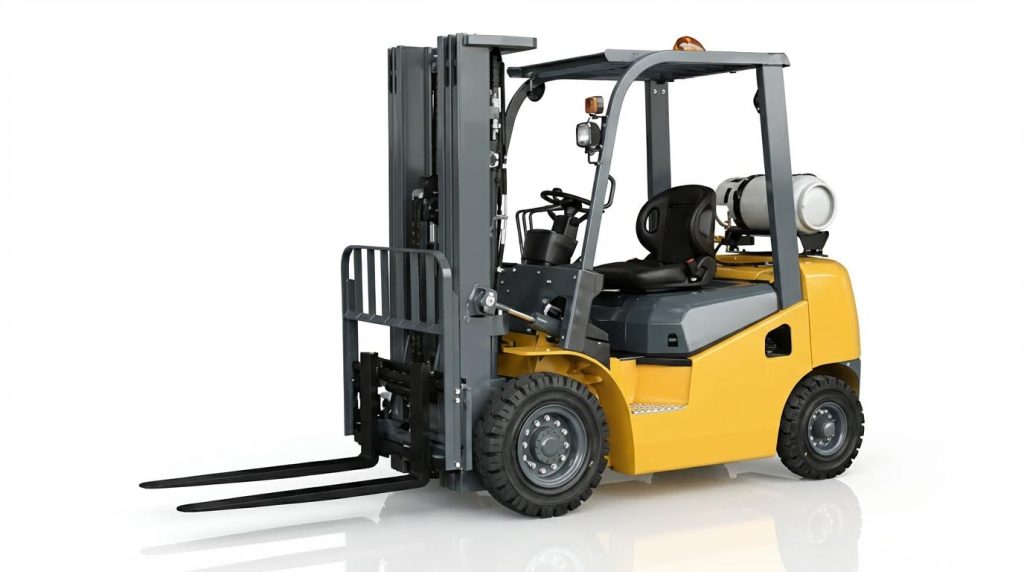
Electric forklift hydraulic systems converted electrical energy into controlled hydraulic power for lifting, tilting, steering, and auxiliary functions. Their architecture combined compact power units, precision valves, and robust actuators to deliver repeatable motion under varying loads. Design choices in component sizing, fluid paths, and protection devices directly determined efficiency, reliability, and safety. Understanding the core layout enabled targeted diagnostics, optimized maintenance, and correct integration with modern electronic controls.
Key Hydraulic Components And Functions
The hydraulic reservoir stored working fluid and allowed air release, thermal expansion, and contaminant settling. An electric motor drove a fixed or variable displacement pump that generated flow and pressure for all hydraulic functions. Control valves directed this pressurized flow to lift, tilt, side-shift, and steering cylinders, converting fluid power into linear or rotary motion. Hoses and rigid pipes formed the distribution network, while filters protected precision components from wear particles and debris. Lift cylinders supported vertical loads at the mast, so designers sized bore and rod diameters to meet rated capacity with adequate safety margins.
Pressure Control, Flow Control, And Safety Devices
Relief valves limited maximum system pressure to protect pumps, hoses, and cylinders from overload and shock events. Manufacturers typically set main relief pressures slightly above the level required for rated capacity, balancing performance and component life. Flow control and throttle valves regulated cylinder speeds, especially during lowering, to prevent uncontrolled descent and mast instability. Check valves maintained load holding by preventing reverse flow when operators released controls or when pumps stopped. Additional safety devices, such as descent speed regulators and load-holding valves on lift circuits, reduced the risk of fork drift and spontaneous lowering under static load. Designers located these devices close to cylinders to minimize the effect of hose failures on load retention.
Interaction With Electric Drive And Control Systems
The hydraulic power unit depended on the traction battery, so battery state of charge directly affected motor torque and pump output. Modern controllers monitored lift commands, motor current, and pressure feedback to coordinate hydraulic demand with available electrical power. Drive and hydraulic controls shared safety interlocks that disabled lifting when operators left the seat or when critical faults occurred. Electronic control units could modulate pump motor speed, providing variable flow on demand and reducing idle energy losses. Integrated diagnostics used sensor data on pressure, temperature, and current draw to detect early signs of cavitation, relief valve chatter, or blocked filters. This interaction supported smoother acceleration, stable lifting at low speeds, and compliance with functional safety requirements.
Fluid Selection, Viscosity, And Temperature Limits
Hydraulic fluids for electric forklifts had to maintain stable viscosity across operating temperatures, typically between 70 °C and 95 °C in the tank. ISO VG 32 to 46 grades offered a balance between cold-start pumpability and sufficient film thickness at high temperature. In cold environments below 0 °C, fleets often switched to lower-viscosity fluids, such as ISO VG 22, to reduce cavitation and sluggish response. Fluid selection also considered oxidation stability, anti-wear performance, and compatibility with seals and hose materials. Operators monitored fluid color, odor, and foaming to detect thermal degradation, air ingress, or water contamination, which accelerated pump and valve wear. Maintaining fluid within specified cleanliness codes and temperature limits significantly extended component life and reduced unplanned downtime.
Transmission Systems In Electric Forklifts
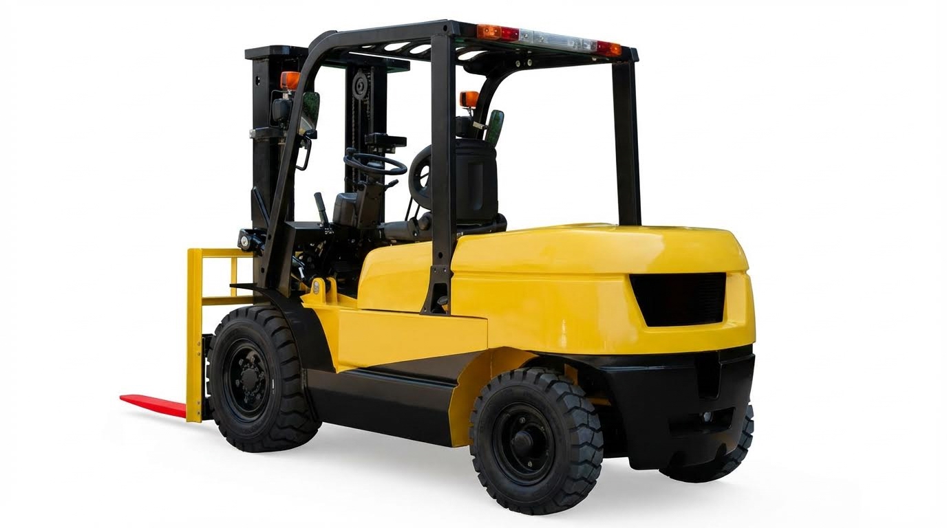
Electric forklift transmissions converted motor torque into controlled tractive effort and regulated travel speed. Designers typically combined torque converters, multi-stage gearboxes, and hydraulic control circuits to match motor characteristics with load and ramp requirements. Robust cooling and oil management protected friction elements and bearings from thermal degradation. Understanding these subsystems enabled engineers and maintenance teams to diagnose drive issues before they affected safety or uptime.
Torque Converters, Gearboxes, And Drive Layouts
Forklift torque converters provided hydrodynamic torque multiplication between the electric or engine-driven prime mover and the gearbox input. Typical faults included speed drop under load, oil aeration with visible bubbles, and abnormal temperature rise in the converter housing. Engineers checked pipeline tightness, converter oil quality, and operating ratio (stall or low-speed operation) to restore efficiency. Gearboxes used planetary or countershaft layouts with wet multi-disc clutches to provide forward, reverse, and speed ranges.
Transmission layouts integrated the torque converter, main gearbox, differential, and drive axle into a compact powertrain module. Incorrect engine-to-gearbox alignment or excessive flywheel runout, above approximately 1.0 mm, increased vibration and bearing loads. Post-repair inspections verified converter placement, shaft concentricity, and proper engagement of splines. Correct shift linkage, throttle cable, and vacuum or control line adjustment ensured that commanded ranges matched hydraulic clutch actuation.
Hydraulic Transmission Oil And Cooling Management
Hydraulic transmission oil acted as power transmission medium, lubricant, and cooling fluid. Manufacturers specified 6# hydraulic transmission oil or equivalent automatic transmission fluids for powershift units, and separate gear oils for manual gearboxes. Recommended operating temperature ranged between 70 °C and 95 °C; sustained operation above 95 °C accelerated seal and friction plate wear. Prolonged low-speed ratio or stall operation reduced converter efficiency and caused rapid oil temperature rise.
Cooling circuits routed oil through a dedicated cooler and cleaned oil pipes. Technicians ensured unobstructed flow and verified that main transmission oil pressure reached at least about 12 kg·cm⁻² after overhaul. Hydraulic control oil circuits typically operated between 1.1 MPa and 1.4 MPa to guarantee reliable clutch engagement and valve function. Regular cleaning of the cooler matrix and confirmation of fan or pump performance maintained stable oil temperatures under heavy-duty cycles.
Common Transmission Fault Modes And Diagnostics
Typical gearbox faults included sticking or worn friction plates, damaged bearings, and degraded seal rings or O-rings. Symptoms included slipping under load, delayed gear engagement, or complete loss of drive. Diagnostics started with checking main oil pressure; abnormally low values indicated triple pump wear or internal leakage. Clutch oil pressure measurements helped distinguish between seal ring wear, control valve sticking, and mechanical clutch damage.
Abnormal oil temperature or visible bubbles suggested aeration, poor pipeline tightness, or deteriorated hydraulic oil. Technicians inspected control valve springs for sticking or breakage when gear selection failed. Torque converter oil pressure checks confirmed whether internal elements or one-way clutches were stuck, especially at high-speed ratios. After repairs, teams cleaned the gearbox cooler and lines, rechecked oil pressures, and validated shift quality during loaded drive tests.
Service Intervals, Oil Analysis, And Life Extension
Transmission service intervals typically followed 500 operating hours or quarterly, whichever occurred first. Standard tasks included draining and replacing transmission fluid, cleaning the magnetic strainer, and measuring clutch pack clearances against OEM specifications. Using factory-specified automatic transmission oil and maintaining correct fill levels reduced internal wear and overheating. Technicians also verified integrity of mounting feet and grounding to prevent vibration and electrical issues in electric drives.
Oil analysis extended transmission life by identifying wear metals such as iron, copper, and aluminium, as well as silica contamination and viscosity shifts. Trending these parameters enabled predictive replacement of pumps, bearings, or clutch packs before catastrophic failure. Combined with regular filter changes and cooler cleaning, structured maintenance programs reduced drive-train breakdowns by up to about 30–50 %. Consistent documentation of pressures, temperatures, and oil condition created a data baseline for future diagnostics and optimization.
Troubleshooting, Reliability, And Predictive Maintenance
Systematic Hydraulic Fault-Finding Procedures
Technicians needed a structured sequence to troubleshoot electric forklift hydraulics efficiently and safely. A typical workflow started with basic checks: verify battery state of charge, main fuses, contactors, and that the hydraulic enable signal reached the motor controller. The next step involved confirming hydraulic fluid level between the MIN and MAX marks with the truck powered down and forks fully lowered, since low level caused cavitation, noise, and slow or no lift. Operators then inspected for visible leaks, wet fittings, or puddles, because any leak above one drop per minute required immediate removal from service under good practice and OSHA expectations.
Once basic conditions were correct, technicians measured motor supply voltage at the pump motor terminals during lift command to confirm adequate voltage and stable current draw. If the motor ran but lifting remained slow, they connected a calibrated pressure gauge to the main test port and compared readings against OEM lift pressure specifications. Low pressure with normal motor speed indicated pump, suction, or relief valve issues, while normal pressure with slow cylinder motion pointed to mechanical binding or flow restrictions. Throughout the process, personnel documented findings on a shift checklist in line with OSHA 1910.178(q)(7) to support trend analysis and reliability improvement.
Diagnosing Pump, Valve, Cylinder, And Hose Issues
Pump diagnosis relied on correlating pressure, noise, and temperature behavior. A noisy pump with foamy or milky oil usually indicated air ingestion on the suction side, so technicians checked suction hose integrity, clamp tightness, and sealing rings, sometimes using plastic film over joints to detect vacuum leaks. If the motor ran smoothly but system pressure stayed below specification, internal pump wear, damaged gears or vanes, or a clogged inlet filter were likely, requiring filter replacement and often pump overhaul. Overheating of the tank and lines under moderate duty suggested internal leakage in the pump or valves, which converted hydraulic power into heat rather than useful work.
Valve troubleshooting focused on specific functional symptoms. Failure to lift with normal pump pressure pointed to a stuck or contaminated lift valve, solenoid failure, or a misadjusted control spool. Spontaneous or creeping lowering under load indicated leakage through the lowering valve, relief valve, or load-holding elements, often due to debris on the seat or weakened springs. Jerky descent or unstable lowering speed frequently came from partially blocked throttle valves or incorrectly set flow controls. Cylinder issues appeared as oil on the rod, uneven extension, or drift at neutral; technicians verified external fittings first, then planned cylinder disassembly and seal replacement if external components were sound. Hoses and pipes required inspection for cracks, bulges, abrasion, and loose crimp collars, with any defect prompting replacement using hoses rated for the system’s maximum pressure and temperature.
Transmission Pressure, Clutch, And Bearing Checks
Electric forklifts with hydraulic transmissions or power-shift gearboxes depended on stable hydraulic pressures for torque converter and clutch operation. Technicians began by checking transmission oil level and condition, ensuring fluid matched the specified grade, typically 6# hydraulic transmission oil or defined automatic transmission oil, and that oil temperature stayed within approximately 70 °C to 95 °C. Using diagnostic ports, they measured main line pressure, clutch pack pressure, and torque converter pressure, comparing values to OEM charts at idle and specified test speeds. Abnormally low main pressure often indicated wear in the triple pump or internal leaks in the valve body.
Clutch diagnostics centered on slip, harsh engagement, or non-shift conditions. Low clutch pressure with correct main pressure suggested worn seal rings or O-rings in the clutch circuits, while normal pressure but persistent slip pointed to worn or glazed friction plates. Technicians checked friction plate flatness, surface condition, and pack clearance against service limits. Bearing faults manifested as noise, vibration, or metal particles in oil analysis; inspections focused on bearing seats, shaft runout, and alignment between engine (or motor) and gearbox, with flywheel or coupling runout kept below about 1.0 mm. After any major repair, they flushed coolers and lines, cleaned magnetic strainers, and confirmed cooler flow and pressure (for example ≥12 bar where specified) to prevent recurrence of thermal and lubrication-related failures.
AI, Sensors, And Digital Twins For Condition Monitoring
Modern fleets increasingly used sensor-based monitoring to improve hydraulic and transmission reliability and to reduce unplanned downtime. Pressure, temperature, vibration, and flow sensors fed data to on-board controllers or fleet management platforms, which applied rule-based logic or machine learning models to detect deviations from baseline behavior. Examples included identifying slow pressure rise during lift, gradual increase in operating temperature at constant load, or growing vibration levels in pump and gearbox bearings. These patterns often preceded traditional failure symptoms, enabling maintenance teams to intervene
Summary Of Best Practices And Future Trends
Effective hydraulic and transmission maintenance programs reduced repair costs by 25–40% and extended forklift life by 3–5 years. Operators and technicians achieved this by integrating daily OSHA 1910.178(q)(7) checks, scheduled fluid and filter changes, and structured diagnostic procedures. Hydraulic reliability depended on maintaining fluid between MIN and MAX marks, eliminating leaks above one drop per minute, and preserving ISO 32–46 cleanliness through 10-micron filtration and periodic oil analysis. Transmission reliability relied on correct automatic transmission oil grades, 500-hour fluid changes, and strict control of operating temperature between 70 °C and 95 °C.
Future practices increasingly used data-driven maintenance, including particle counting to ISO 4406, TAN tracking, and transmission oil spectroscopy for wear metals. Electric forklifts benefited from battery health monitoring, equalization charge records, and environmental controls in battery rooms to stabilize hydraulic and drive performance. Cold-climate adaptations, such as ISO 22 fluids and adjusted tire pressures, improved safety and reduced cold-start wear. These approaches supported predictive maintenance strategies that reduced unplanned hydraulic downtime, which previously accounted for approximately 42% of failures.
In implementation, sites needed standardized checklists, timestamped leak logs, and integration of sensor data into maintenance management systems. Pressure, temperature, and vibration sensors on pumps, valves, clutches, and bearings enabled early detection of drift from setpoints and OEM specifications. Digital twins and AI-based models increasingly supported what-if simulations for hydraulic circuits and transmissions, improving root-cause analysis and overhaul timing. A balanced strategy combined conservative fluid and seal management with advanced analytics, allowing fleets to transition gradually from reactive and preventive maintenance toward fully predictive, condition-based programs while maintaining regulatory compliance and safety margins.