Electric forklift specification required a rigorous understanding of capacity, lift height, and stability. This guide linked rated capacity and load center to real warehouse geometries, from overall lowered height to maximum fork height. It then connected mast design, travel and lift speeds, and structural integrity to safety, throughput, and lifecycle cost. Finally, it provided an engineering framework to specify safe, efficient electric forklifts for modern, high-bay, space-constrained facilities.
Core Concepts Of Forklift Capacity And Height
Core capacity and height concepts defined the safe operating envelope of electric forklifts. Engineers used these parameters to translate catalog data into real warehouse performance. Misinterpretation of rated capacity or height terms often led to overloads, racking impacts, or poor truck selection. A rigorous understanding of load center, de‑rating, and mast geometry therefore formed the basis for any engineering specification.
Rated Capacity, Load Center, And De-Rating
Rated capacity described the maximum load a forklift could lift to its specified height at a defined load center. Manufacturers typically specified this at a 500 mm load center for 1.0–1.5 t class trucks, and comparable values in millimetres for larger electric forklifts. The load center was the horizontal distance from the fork face to the load’s center of gravity. When the actual load center exceeded the rated value, the effective capacity decreased, a process known as de‑rating.
De‑rating also occurred at higher lift heights and with attachments such as clamps or side‑shifters. For example, a 1,500 kg reach truck rated at 500 mm load center and 6,000 mm lift height could not safely handle 1,500 kg at a 700 mm load center at the same height. Engineers therefore used manufacturer de‑rating charts that related height, load center, and attachment weight to an allowable capacity. OSHA guidance required operators to respect the revised capacity shown on the truck’s data plate whenever attachments or non‑standard loads were used.
Temperature, tire condition, and structural wear further reduced the realistic working capacity over the truck’s lifecycle. Conservative engineering practice applied safety factors when sizing trucks for critical racking or high‑value loads. This ensured that even with partial de‑rating from battery state, mast wear, or uneven floors, the truck still operated within its stable region.
Key Height Terms: OALH, OARH, MFH, FFH
Engineers used several standardized height terms to match forklifts to buildings and racking. Overall Lowered Height (OALH) described the truck’s height from floor to mast top when fully lowered. This value determined whether the truck could pass under door headers, mezzanines, trailer roofs, or low sprinkler lines. It was critical for specifying trucks that had to enter semi‑trailers, which typically offered about 2.4 m internal clearance.
Overall Raised Height (OARH) was the maximum mast height from floor to mast top with the mast fully extended. OARH helped engineers check for interference with roof trusses, lighting, ductwork, or sprinkler mains during high stacking. Maximum Fork Height (MFH) described the highest elevation of the fork tines themselves, not the mast top. MFH had to exceed the top rack beam plus a clearance margin, often 150–200 mm, to allow clean lifting without dragging pallets.
Free Fork Height (FFH), or free lift, described how high the forks could rise before the mast stages extended above OALH. FFH was essential in low‑ceiling areas where the truck needed to place loads above floor level while still remaining under a fixed overhead limit. Reach trucks typically offered higher FFH than comparable counterbalance trucks, which made them suitable for dense racking under constrained roof heights. OSHA guidance required operators to understand these dynamic height ranges to avoid striking overhead fixtures.
Mast Stages And Free Lift Fundamentals
Mast design strongly influenced both lift height and clearance behavior. Single‑stage masts used a single vertical channel set and offered limited MFH with minimal free lift. They suited low‑stack applications where ceiling height was not constrained and the operator worked close to floor level. Their simple structure provided high rigidity and good visibility.
Two‑stage masts incorporated an inner moving channel, enabling higher MFH while keeping OALH moderate. Designs with central lift cylinders combined good lift height with relatively low mast profiles, making them appropriate for covered loading docks and doorways with restricted clearance. Two‑stage masts with side cylinders improved forward visibility by removing the central obstruction, which aided precise fork positioning into pallets and racks.
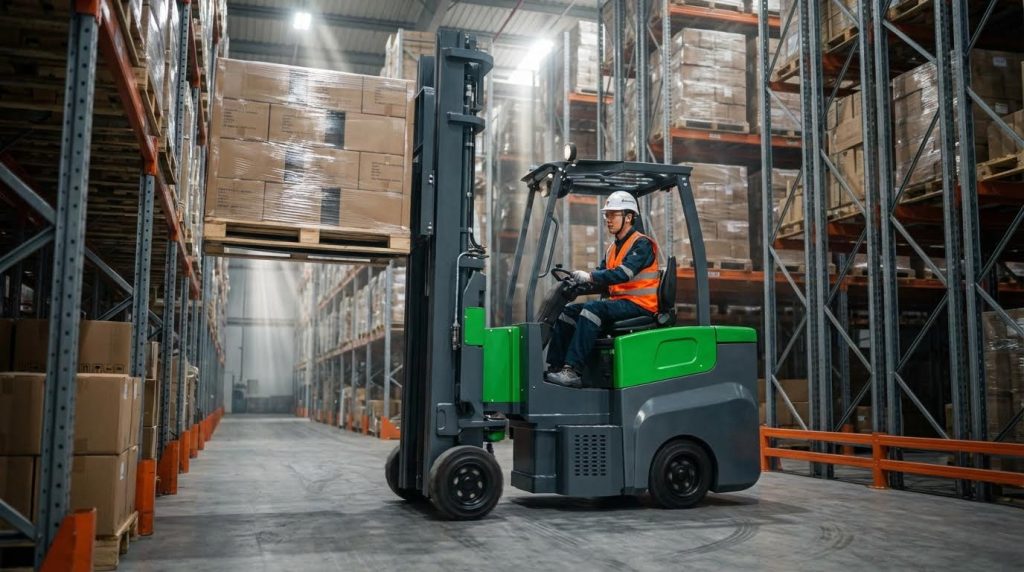
Three‑stage masts added a third nested channel to achieve very high MFH while preserving a low OALH and large FFH. These masts were typical in high‑bay warehouses and distribution centers where racks reached 6,000 mm or more, as seen in reach trucks with extended mast heights up to about 6,840 mm. High FFH allowed operators to lift within trailers or under low beams before extending the outer mast stages. Engineers balanced mast complexity, weight, and deflection against required lift height and aisle geometry to maintain stability and operator visibility.
Stability Triangle And Dynamic Effects
The stability triangle concept described the static stability of a forklift. For three‑wheel or four‑wheel trucks, the triangle connected the points where the wheels contacted the floor. The combined center of gravity of the truck and load had to remain within this triangle to avoid tip‑over. As the load mass increased or the load center moved forward, the combined center of gravity shifted toward the triangle’s front edge.
Lift height amplified these effects. Raising a heavy pallet to 6,000 mm on a reach forklift increased the overturning moment because the center of gravity moved upward and sometimes slightly forward. Dynamic actions such as braking, accelerating, turning, or mast tilting further displaced the effective center of gravity. OSHA therefore recommended never traveling with the load elevated and avoiding sharp turns with raised forks.
Floor gradients and surface irregularities also influenced stability. Gradeability ratings, such as 15% laden for 1.0–1.5 t electric forklifts, indicated the maximum slope the truck could climb without losing stability or traction. Engineers specified operating zones and travel paths that limited slopes and cross‑falls for loaded trucks. They also considered tire type, inflation, and suspension compliance, which affected how quickly the center of gravity could move outside the stability triangle during dynamic maneuvers.
Engineering Selection Of Capacity And Lift Height
Engineering selection of electric forklifts required a structured match between load, height, and building constraints. Designers evaluated rack geometry, aisle layout, and structural clearances before choosing truck class, mast type, and capacity. Proper matching minimized de-rating, collision risk, and congestion while maintaining required throughput. The following subsections described a practical engineering workflow from rack definition to model comparison.
Defining Rack Heights And Safety Clearances
Engineers first measured the top beam elevation of the highest rack level. They then added the maximum pallet and load height to obtain the required fork level, often called required maximum fork height. Best-practice guidance from manufacturers suggested adding approximately 150 mm to 200 mm clearance above the top shelf. This allowance enabled the operator to lift cleanly off the beams without dragging product or striking rack bracing.
Designers also checked the relationship between maximum fork height and the truck’s overall raised height. They ensured that sprinkler lines, lighting, and roof trusses remained above the mast’s overall raised height with a safety margin. For high-density warehouses, engineers often back-calculated maximum allowable rack height from building clear height minus this required mast clearance. They then selected a mast configuration whose rated maximum fork height exceeded the calculated requirement at the target load capacity.
Matching Mast Type To Ceiling And Door Limits
Mast selection depended strongly on the available clearances at doors, dock openings, and internal structures. Engineers used the overall lowered height to verify that the truck could pass under door headers and into semi-trailers, which typically required about 2.4 m internal clearance. For low buildings with moderate rack heights, two-stage masts with central cylinders offered high lift with relatively low lowered height. These masts suited operations that needed stacking in halls with limited ceiling height and frequent doorway passages.
Where operations required high stacking with constrained lowered height, engineers favored three-stage masts with high free lift. These masts allowed the forks to reach substantial heights before the inner mast sections extended above the base height. In low-level applications, single-stage or two-stage side-cylinder masts improved forward visibility and simplified maintenance. Throughout selection, engineers referenced OSHA guidance on knowing the dynamic range from overall lowered height to overall raised height to avoid contact with overhead fixtures and building services.
Comparing Counterbalance vs. Reach Trucks
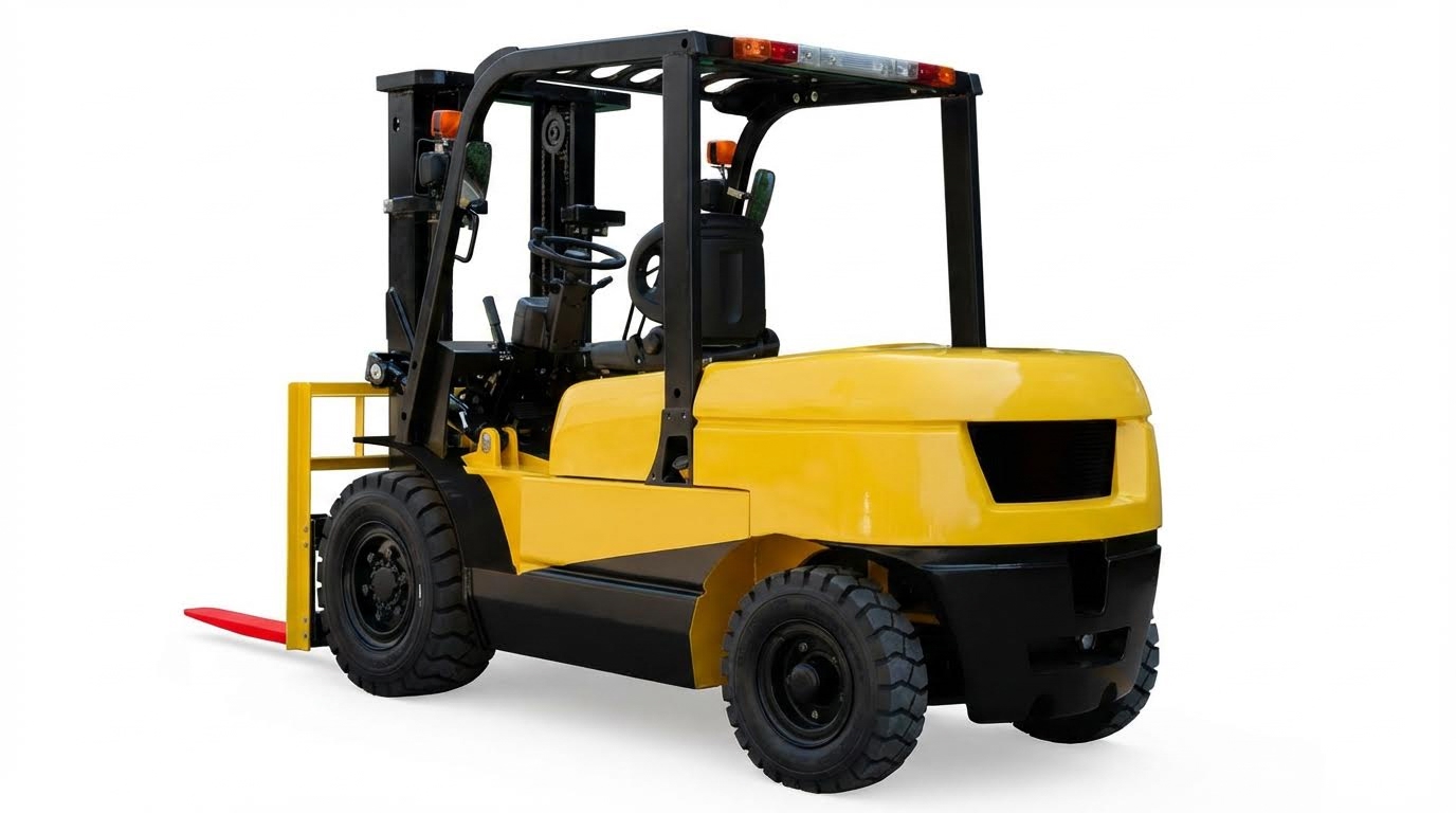
Counterbalance electric forklifts provided direct load handling with the forks extending in front of the drive axle. They required wider aisles because the truck body needed room to rotate fully into the rack face. Typical overall widths for 1.0 t to 1.5 t counterbalance trucks were about 1,090 mm, while larger 8,000 lb to 12,000 lb trucks reached 1.2 m to 1.35 m. Their length to fork face, often between 2,150 mm and 2,870 mm, drove turning radius and aisle width requirements.
Reach trucks shifted the mast forward on a pantograph or moving carriage, allowing operation in narrower aisles. The CQD reach truck, for example, had an overall width of about 1,090 mm but a much shorter length to fork face of roughly 1,185 mm. This geometry reduced required aisle width while still achieving lift heights up to about 6,000 mm. Engineers compared rack depth, pallet overhang, and required aisle width to decide between counterbalance and reach concepts, often favoring reach trucks for high-bay, narrow-aisle storage.
Case Data: 1–1.5 t vs. 8–12 k lb Electric Trucks
Quantitative comparison helped engineers match truck families to application envelopes. Light-duty counterbalance models such as 1.0 t and 1.5 t electric forklifts offered rated capacities of 1,000 kg and 1,500 kg at a 500 mm load center. Their lift heights ranged from about 3,000 mm to 6,500 mm, with overall widths near 1,090 mm and length to fork face about 2,150 mm. These trucks suited standard pallet work, moderate rack heights, and relatively tight but not ultra-narrow aisles.
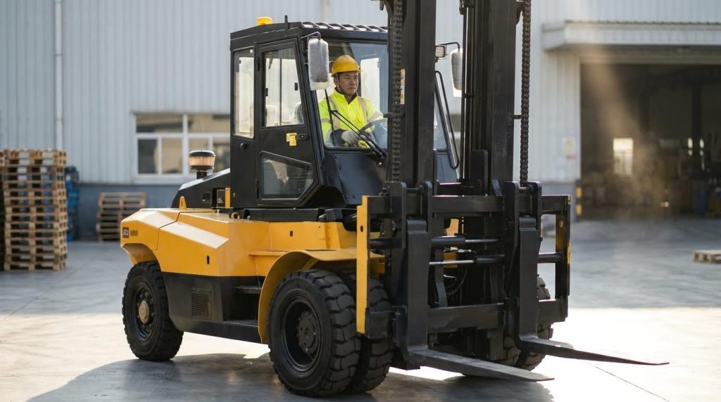
Large electric counterbalance trucks, such as 8,000 lb to 12,000 lb models, delivered capacities from approximately 3,600 kg to 5,400 kg. Their length to fork face extended from about 2,510 mm to 2,870 mm, and overall width ranged from roughly 1,210 mm to 1,350 mm. These dimensions increased turning radius and required wider aisles but enabled handling of heavy industrial loads, dies, and machinery. Engineers balanced capacity against maneuverability, verifying that floor loading, turning spaces, and rack designs could safely accommodate the larger trucks without compromising throughput or safety margins.
Performance, Safety, And Lifecycle Considerations
Performance, safety, and lifecycle aspects strongly interacted in electric forklift engineering. Designers balanced lift speed, travel speed, and handling stability with structural robustness and maintenance intervals. Fleet engineers evaluated how hydraulic health, tire condition, and battery performance influenced real, not catalog, capacity and lift height. Increasingly, operators used data-driven tools to predict degradation and avoid capacity-related incidents.
Lift Speed, Travel Speed, And Throughput
Lift speed and travel speed directly constrained pallet throughput per hour. Large electric counterbalance trucks, such as 8,000–12,000 lb units, reached lift speeds between about 11 and 22 m/min depending on voltage and model. Smaller 1.0–1.5 t forklifts typically lifted at 280–310 mm/s, while reach trucks lifted at about 135 mm/s under load and 220 mm/s unloaded. Engineers sized motors, hydraulic pumps, and control valves so that vertical and horizontal motions remained stable near rated capacity and maximum lift height.
Throughput modeling considered acceleration, deceleration, and cornering limits, not only peak travel speed. Large electric trucks traveled at roughly 3.3–4.9 m/s, while narrower warehouse trucks operated slower but turned tighter. Safety standards and internal policies usually limited travel speed when carrying elevated loads or operating in congested aisles. Advanced controllers often derated speed automatically with steering angle, mast height, and load weight to maintain stability.
Structural Integrity, Hydraulics, And Tires
Structural integrity governed whether a forklift safely sustained its rated capacity at the specified load center and lift height. Frames, masts, and overhead guards required periodic inspection for cracks, deformation, or corrosion, particularly around welds and mast channels. Any distortion in the mast rails or carriage altered load distribution and could reduce safe maximum fork height. A weakened frame also changed the center of gravity envelope and reduced the stability margin inside the stability triangle.
Hydraulic health determined smooth, predictable lifting. Maintenance teams checked chains, cylinders, and hoses for wear, pitting, and leaks, and verified that hydraulic fluid type and level matched the manufacturer specification. Irregular lift motion during a light test load indicated internal leakage or valve issues that could worsen under full load. Tires affected both stability and effective capacity, since low pressure or uneven wear changed ride height, tilt geometry, and braking performance.
Battery State, Duty Cycle, And De-Rating
Battery state of charge and condition directly influenced lifting capacity and speed. As voltage sagged under high current, lift speed dropped and travel acceleration decreased, reducing effective throughput. Heavy duty cycles with frequent high lifts and long travel runs required larger battery packs or opportunity charging strategies. Engineers modeled worst-case duty cycles to avoid excessive voltage drop that might compromise hydraulic pressure at maximum lift height.
Manufacturers typically specified rated capacity at nominal voltage and temperature. In practice, fleets observed de-rating at low state of charge, low temperatures, or when batteries aged. Proper charging discipline, electrolyte maintenance for lead-acid systems, and adherence to charge–discharge limits for lithium-ion packs mitigated performance loss. Hour-meter and battery-usage data supported planning for mid-life de-rating and timely battery replacement.
Digital Twins And Predictive Maintenance
Digital twins and connected telematics increasingly supported predictive maintenance for electric forklifts. Virtual models integrated sensor data on mast cycles, lift heights, load weights, battery current, and travel profiles. Engineers used these data to estimate fatigue damage in mast welds, chain stretch, and hydraulic component wear. Predictive algorithms flagged abnormal lift times or pressure patterns that suggested internal leakage or pump degradation.
Such systems helped schedule maintenance before capacity or lift height performance degraded below safe thresholds. Operators correlated fault codes and event logs with specific tasks, aisles, or operators to refine training and routing. Over time, fleets optimized mast selection, battery sizing, and service intervals based on real operating profiles rather than catalog assumptions. This data-driven approach reduced unplanned downtime and extended the safe lifecycle of electric lifting equipment.
Summary: Specifying Safe, Efficient Electric Lifts
Engineering a safe electric forklift specification required a simultaneous view of capacity, height, and environment. Rated capacity at a defined load center, combined with de‑rating at height and with attachments, determined the real usable envelope. Height terminology such as OALH, OARH, MFH, and FFH allowed precise checks against doors, racks, trailers, and ceiling fixtures in line with OSHA guidance. Mast stage selection, from single to three‑stage with high free lift, linked these constraints to the required stacking strategy.
Market data showed how compact 1.0–1.5 t class trucks and large 8–12 k lb electric counterbalance trucks addressed very different duty profiles. Reach trucks with high MFH and narrow chassis extended vertical and horizontal reach inside constrained aisles, while counterbalance trucks traded aisle width for versatility and higher base capacity. Performance metrics such as lift speed, travel speed, and gradeability directly influenced throughput, but only when structural integrity, hydraulics, and tires remained within specification. Battery state and duty cycle further modified available performance, making de‑rating curves and energy management central design inputs.
In practice, engineers benefited from a requirements‑first workflow: define maximum rack height plus 150–200 mm clearance, map all entry and ceiling constraints, then select mast and truck class that satisfy both MFH and OALH limits at the required capacity. Digital twins and predictive maintenance tools increasingly supported this process by simulating stability, wear, and energy use over the asset lifecycle. Future developments would likely tighten the integration between real‑time sensor data, automated de‑rating, and fleet‑level optimization, but the fundamentals would stay constant: respect the stability triangle, never exceed rated capacity at height, and verify that the truck’s dynamic envelope fits the building before it ever lifts a load.