If you want a practical answer to how do electric forklifts work, you need to see how the battery, motors, controllers, hydraulics, and chassis all tie together. This article walks through power flow from the battery to the drive wheels, explains motor and controller choices, and shows how hydraulics and batteries affect stability and runtime. You will see what actually limits speed, lift, and duty cycle, and how to match an electric forklift to your aisles and shifts. Use it as a technical roadmap when you specify, compare, or troubleshoot electric trucks.
Core Architecture Of Modern Electric Forklifts
If you want to understand how do electric forklifts work, you must start with the core architecture. Electric trucks turn battery energy into traction, lifting, and steering through a tightly integrated system of power electronics and motors. This section breaks down how power flows, which motor types are used, and how each motor group supports safe, efficient material handling.
Power flow from battery to drive wheels
At system level, the power path in an electric forklift is a DC energy chain with controlled conversion points. Knowing this path helps you size batteries, cables, and controllers correctly and avoid voltage drop and overheating.
- Battery stores DC energy (typically 24–80 V depending on truck class).
- Main contactor and safety interlocks connect/disconnect the pack.
- Traction controller converts battery DC to controlled AC or DC for the drive motor.
- Drive motor converts electrical power into torque at the drive axle.
- Final drive (gears) multiplies torque and reduces speed at the wheels.
- Regenerative braking sends power from the motor back to the battery during deceleration. The drive motor acts as a generator when braking
Directional control and safety logic
The propulsion controller manages acceleration, braking, and direction. A directional selector reverses motor polarity or phase sequence to switch between forward and reverse. Operators must stop fully before direction changes to avoid drivetrain shock and load instability. Smooth ramp-up of torque is essential to prevent sudden shifts in the load center and tipping risks. Propulsion controls in electric forklifts follow these principles
This energy path is the backbone of how do electric forklifts work in day-to-day operation, from creeping in tight aisles to full-speed travel between docks.
AC, DC, and IPM motor types and roles
Electric forklifts use several motor technologies. Each has different torque, efficiency, and control characteristics, which affect range and performance.
| Motor type | Key characteristics | Typical role in forklifts |
|---|---|---|
| Conventional AC induction | Simple structure, reliable, low maintenance, high efficiency at near-constant speed, but lower power factor and reduced efficiency at variable speeds AC motor characteristics AC efficiency behavior | Traction, hydraulic pump on many modern trucks |
| Conventional DC (wound-field) | High starting torque, precise speed control, good wide-range performance, more maintenance due to brushes and commutator DC motor advantages | Legacy traction and lift motors, some steering drives |
| Brushless DC (BLDC) | Linear torque–speed curve, maximum torque at start then decreasing to rated torque as speed rises; high efficiency over a broad speed range BLDC torque–speed behavior | High-efficiency traction, pump motors |
| Interior Permanent Magnet (IPM) | Up to about 35% energy savings versus conventional AC in variable-demand duty, efficient at both high-speed/low-torque and low-speed/high-torque, long traction system life IPM energy savings | Premium traction motors in high-duty or energy-sensitive fleets |
From a control perspective, AC, BLDC, and IPM drives all rely on inverters to modulate motor current and speed from the DC battery bus. DC wound-field motors use choppers and field control instead. The selection depends on required efficiency, cost, and maintenance strategy.
- AC induction: good for rugged, low-maintenance fleets with moderate speed variation.
- DC wound-field: suited where very fine low-speed control is critical and brush maintenance is acceptable.
- BLDC/IPM: preferred when maximum runtime per charge and compact motors are priorities.
These technology choices are central to how do electric forklifts work efficiently while meeting different duty cycles and energy budgets.
Traction, lift, and steering motor functions
Electric forklifts normally separate traction, lift, and steering into dedicated motor groups. This improves controllability and allows each motor to be optimized for its torque and speed profile.
| Motor function | Primary job | Typical motor traits |
|---|---|---|
| Traction motor | Drive the wheels for forward/reverse travel and acceleration | High starting torque, wide speed range, smooth torque control; often DC traction or AC/BLDC/IPM with inverter control Traction motor role |
| Lift (hydraulic pump) motor | Drive the hydraulic pump for mast lifting and tilting | Designed for intermittent heavy load, high torque at low speed, fast response to lever commands |
| Steering motor | Power the rear-wheel steering mechanism | Low power, precise bidirectional control, optimized for frequent small movements rather than continuous duty |
- All three motor groups share the same DC battery bus and are coordinated by the truck’s control system.
- Traction and lift motors often draw the majority of current; steering is a minor but safety-critical load.
- Functional separation allows independent protection, such as limiting lift speed at high travel speed for stability.
Why DC traction motors are still common
DC traction motors provide very high starting torque and good speed regulation, which suits battery-powered traction and lifting equipment. Series-excited DC motors in particular deliver hyperbolic characteristics: high torque at low speed and rising speed under light load, which works well for forklifts and tractors. Series DC motors in forklifts
Together, these dedicated motors and their controllers form the practical answer to how do electric forklifts work: the battery feeds a coordinated set of traction, hydraulic, and steering drives that move, lift, and position loads safely in tight industrial spaces.
Motors And Controllers: Torque, Speed, And Efficiency
DC excitation methods and torque–speed behavior
Understanding DC excitation is key to explaining how do electric forklifts work at low speeds and high loads. Different excitation types change how much starting torque you get, how speed reacts to load, and how stable the truck feels with a manual pallet jack in the air.
- Separately excited (sepex) DC motors
- Field winding has its own supply, independent of the armature. Separately excited motors power the field from an independent source.
- Controller can adjust field current and armature voltage separately.
- Gives precise speed control over a wide range.
- Useful for lift motors where smooth positioning is critical.
- Series excited DC motors
- Field winding in series with the armature, so the same current flows through both. Series excited motors connect the excitation winding in series with the armature.
- Produce very high starting torque at low speed.
- Speed rises sharply when load is light (hyperbolic characteristic).
- Common choice for traction in battery forklifts that must start on ramps.
- Shunt (parallel) excited DC motors
- Field winding in parallel with the armature. Shunt excited motors connect the excitation winding in parallel with the armature.
- Field current is almost constant, so speed is nearly constant.
- Lower starting torque than series type.
- Useful where constant travel speed is more important than maximum pull.
- Compound excited DC motors
- Combine series and shunt windings. Compound motors use both series and parallel connections.
- Blend high starting torque with better speed regulation.
- Useful for mixed-duty forklifts that see both ramps and long travel.
Torque–speed behavior in DC forklift motors
Series DC motors show a “hyperbolic” torque–speed curve. Torque is very high at stall and low speed, then drops quickly as speed increases, while no-load speed can become dangerously high if the truck runs unloaded. This is why traction controllers limit maximum speed and prevent free over‑revving. In contrast, shunt and sepex motors give flatter speed curves, so travel speed changes little with load, which makes operation more predictable for the driver.
From a practical standpoint, the high starting torque of series and compound DC motors answers a core part of how do electric forklifts work under heavy hydraulic pallet truck: they deliver strong wheel torque at low speed without a multi‑ratio gearbox, which simplifies the drive axle.
BLDC and IPM motors for high-efficiency traction
Modern electric forklifts increasingly use AC, BLDC, and IPM motors in the drive axle to improve efficiency and runtime. These motor types cut losses across the duty cycle and reduce maintenance compared with brushed DC designs.
| Motor type | Key characteristics | Torque–speed behavior | Impact on forklift performance |
|---|---|---|---|
| Conventional AC induction | Simple, rugged, low maintenance, high efficiency at near-constant speed AC motors are reliable and efficient but need reactive current | Good efficiency at rated speed; drops as speed is varied AC motor efficiency declines when speed varies | Suited to applications with steady travel speeds and moderate ramp work |
| Brushless DC (BLDC) | Electronic commutation, no brushes, high efficiency over a wide speed range Brushless DC motors sustain high efficiency across a broad speed range | Nearly linear torque–speed curve; maximum torque at start, decreasing toward full-load torque as speed rises BLDC motors provide maximum starting torque that decreases with speed | Strong launch on ramps, predictable acceleration, longer runtime per charge |
| Interior Permanent Magnet (IPM) synchronous | Permanent magnets embedded in rotor; high power density and efficiency | Efficient at both high-speed–low-torque and low-speed–high-torque operation IPM motors operate efficiently over wide torque–speed ranges | Can cut traction energy use by up to about 35% vs conventional AC systems, extending battery runtime IPM motors achieve up to 35% energy savings |
- Why BLDC/IPM for traction
- High starting torque without brushes allows compact drive units.
- High efficiency over variable speeds matches stop‑start warehouse duty.
- Lower heat generation simplifies cooling and improves reliability.
- Operator feel
- Smooth, linear torque–speed response makes throttle control intuitive.
- Better low‑speed control during semi electric order picker positioning and tight turns.
- Stronger regenerative capability for energy recovery during deceleration.
These characteristics are central to how do electric forklifts work in high‑throughput warehouses: BLDC and IPM traction systems deliver quick, smooth acceleration while keeping battery draw low, which allows longer shifts between charges.
Controller specs, protection, and regenerative braking
The motor controller is the “brain” between the battery and motors. It shapes current, protects components, and recovers energy whenever the operator slows down.
| Controller parameter | Typical value / feature | Function in electric forklifts |
|---|---|---|
| System voltage | ≈72 V for many BLDC traction systems Example: 72 V BLDC motor controller | Balances current levels, cable size, and safety |
| Continuous / peak current | ≈240 A continuous, up to ≈480 A for ≤8 s 240 A continuous, 480 A peak | Continuous current sets rated traction; peak current covers starts and ramps |
| Efficiency | Up to about 95% at full load Controller efficiency of 95% at full load | Minimizes heat, extends battery runtime |
| PWM frequency | 0–5 kHz for BLDC; up to ≈18 kHz in some DC controllers 0–5 kHz PWM control H-series controllers work up to 18 kHz | Controls motor torque smoothly and reduces audible noise |
| Environmental rating | IP67, −40 °C to 85 °C operating range IP67 protection and wide temperature range | Ensures reliability in cold stores, wet docks, and dusty warehouses |
| Communication | CAN bus, Bluetooth monitoring CAN bus and Bluetooth 5.3 monitoring | Integrates with truck diagnostics and fleet management |
| Protection features | Overcurrent limits up to ≈400 A, self‑diagnostic circuits, battery level monitoring H-series controllers handle up to 400 A and monitor battery level | Prevents component damage and deep battery discharge |
- Core protection and safety functions
- Current limiting to protect motors and wiring during stalls or impacts.
- Temperature monitoring to derate power when electronics run hot.
- Low‑voltage cutback to avoid over‑discharging the traction battery.
- Self‑diagnostics to log faults and support preventive maintenance.
- Regenerative braking behavior
- On pedal release, the controller switches the traction motor into generator mode.
- Generated power flows back into the battery, extending runtime. Electric forklifts use regenerative braking to slow the vehicle and return energy to the battery
- Regen torque ramps in smoothly to avoid shifting the load center abruptly.
- Mechanical brakes finish the stop below low speeds or in emergency conditions.
Energy optimization in modern controllers
Some advanced controllers adjust output automatically under light loads to increase efficiency. One design extended battery runtime by up to about 18% during partial‑load cycles by optimizing light‑load efficiency and balancing MOSFET currents, reaching module performance near 99.3% over 10,000 hours of operation. Light-load efficiency enhancement and MOSFET current balancing improve long-term performance This directly supports longer shifts and smaller battery sizes for the same workload.
Putting these elements together, how do electric forklifts work from the driver’s right foot to the drive wheels? The controller reads pedal position, calculates required torque, switches hundreds of amps in a controlled PWM pattern, protects the system from abuse, and recovers energy whenever the truck slows, turning the motor and battery into a tightly managed, efficient powertrain.
Hydraulics, Batteries, And System-Level Design
Hydraulic lift and tilt circuits and load stability
Hydraulics are the muscle that turn motor power into vertical lift and mast tilt. If you want to understand how do electric forklifts work in real aisles, you must understand how the hydraulic circuit controls the load’s center of gravity and stability. The operator only sees levers, but behind them is a precise oil-flow and pressure-control system that decides whether a truck feels smooth and safe or nervous and unstable. Smooth, well‑damped motion is a design requirement, not a luxury. Rapid lifting or lowering can destabilize loads and increase tip‑over risk.
In a modern electric forklift, the hydraulic pump is usually driven by a dedicated electric motor. Flow goes through control valves to lift and tilt cylinders, then returns to tank. The way these components are sized and tuned sets maximum lift speed, tilt speed, and how aggressively the mast stops at the end of stroke.
| Hydraulic element | Main function | Impact on load stability |
|---|---|---|
| Gear or piston pump | Generate flow and pressure for lift/tilt | Higher flow = faster mast motion; too high can cause jerky moves |
| Lift control valve / lever | Meter oil to lift cylinders for raising/lowering | Controls vertical acceleration; poor metering can bounce or shock-load the mast |
| Tilt control valve / lever | Meter oil to tilt cylinders for mast forward/backward tilt | Controls load angle; excessive forward tilt shifts CG outward and can reduce stability |
| Lift cylinders | Convert pressure into vertical force | Cylinder bore and stroke define lift capacity and mast stiffness |
| Tilt cylinders | Rotate mast around tilt pivots | Back-tilt pulls CG toward the truck; forward tilt pushes CG away |
| Relief / safety valves | Limit maximum pressure in the circuit | Prevent overload that could buckle components or drop loads suddenly |
How the operator uses the hydraulic levers is just as important as the hardware. Safe operating rules are built into most training programs and should be supported by the machine’s tuning.
- Use smooth, progressive lever movements to avoid sudden CG shifts.
- Keep the mast slightly back-tilted while traveling to pull the load toward the truck.
- Only use forward tilt when placing or picking a load at height. Forward tilt is typically permitted only during load placement or retrieval.
- Reduce lift and tilt speeds when operating near rated capacity or at upper mast stages.
- Coordinate hydraulic motion with travel speed; avoid turning while lifting or lowering.
Why hydraulic tuning matters for “how do electric forklifts work”
Electric forklifts use precise motor control for the hydraulic pump, so engineers can map pump speed to lever position. This lets the truck deliver fast lift when lightly loaded and automatically slow down near full height or near the pressure limit. That is a key part of how do electric forklifts work differently from older engine trucks with fixed‑speed pumps.
Lead-acid vs. lithium-ion batteries and BMS
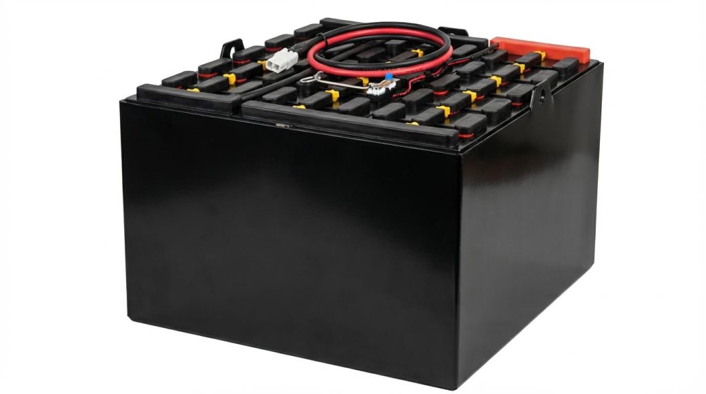
The battery is the energy tank that feeds traction and hydraulic motors, and it shapes how do electric forklifts work over a shift. Today, most new high‑intensity applications move from lead‑acid to lithium‑ion because of efficiency, charging flexibility, and maintenance savings. A Battery Management System (BMS) is the “brain” that makes lithium truly viable for demanding warehouse duty.
| Parameter | Lead-acid traction battery | Lithium-ion forklift battery |
|---|---|---|
| Typical energy efficiency | ≈75–80% charge–discharge efficiency (baseline) | ≈90–95% efficiency, reducing energy waste and heat generation (90–95% cited) |
| Charging pattern | Long, full charges; cool‑down required; opportunity charging not recommended | Fast, opportunity charging during breaks with no cool‑down needed (no cooling-off periods) |
| Charge time (typical) | Often 8+ hours for full recharge | Roughly 1–2 hours for full charge in many systems (1–2 hour full charges) |
| Runtime strategy | Single long shift or battery swaps between shifts | 24/7 operation via quick top‑ups; no battery swaps needed in many fleets |
| Maintenance | Watering, equalization, acid cleanup, corrosion control | No watering or acid; sealed packs cut maintenance labor by about 80–90% (maintenance reduction) |
| Service life (cycles) | Lower; more frequent replacements over 10 years | About 3,000–5,000 cycles, reducing replacements and lifecycle cost (3,000–5,000 cycles) |
| Total cost of ownership | Lower purchase price but higher energy and maintenance cost | Estimated savings of roughly $6,000–$12,000 per truck over 10 years (10‑year savings range) |
| Environmental profile | Acid and lead handling; more frequent replacements | Lower energy use (≈30–40% less), high recyclability, no acid/lead disposal (energy and recyclability data) |
The BMS is what allows lithium to safely deliver this performance in an electric forklift. It monitors each cell, balances them, and protects against abuse that would quickly destroy an unprotected pack.
- Monitors individual cell voltages with high accuracy (around ±0.05 V resolution). Accurate cell monitoring extends life.
- Tracks temperature gradients with ≈1 °C resolution to prevent localized overheating.
- Balances charge and discharge between cells to avoid weak‑cell early failure.
- Estimates state of charge and remaining useful life within a narrow error band (around 5%).
- Provides protection against over‑charge, over‑discharge, over‑current, and excessive temperature. These protections are standard BMS functions.
Typical BMS hardware envelope
A common forklift BMS design handles pack voltages up to about 80 V with very low standby current (on the order of tens of milliamps) and total power draw of only a few watts. One example package weighs around 300 g and measures roughly 150 mm × 61 mm × 28 mm, which makes it easy to integrate inside standard battery trays without reducing cell volume. Representative BMS specifications.
From a system‑level perspective, switching from lead‑acid to lithium with BMS changes how do electric forklifts work in three big ways: energy efficiency improves, charging becomes part of the workflow instead of a separate shift, and maintenance shifts from daily hands‑on tasks to mostly digital monitoring.
Matching powertrain to duty cycle and aisle layout
To specify an electric forklift correctly, the powertrain and battery must match the duty cycle and aisle layout. This is where “how do electric forklifts work” moves from theory to practical sizing. You must align traction motor power, hydraulic pump demand, battery capacity, and charging strategy with real travel distances, lift heights, and cycle times.
- Duty cycle characterization
- Percent of time spent driving loaded vs. empty.
- Average and peak lift heights per cycle.
- Number of lifts and tilts per hour.
- Stop‑start frequency and use of regenerative braking.
- Number of shifts per day and allowed charging windows.
- Aisle and layout constraints
- Aisle width and turning radius, which define required steering geometry and speed limits.
- Ramp gradients between docks and storage areas, which drive traction torque requirements.
- Floor condition and surface friction, affecting required tire type and traction control.
- Stacking heights and overhead obstructions, which influence mast type and hydraulic flow needs.
Once you know the duty and layout, you can match the powertrain elements more precisely instead of oversizing everything “just in case.” That reduces cost and improves efficiency.
| Design decision | Key engineering question | Typical design response |
|---|---|---|
| Battery chemistry and capacity | Is the application single‑shift light duty or multi‑shift heavy duty? | Light duty: lead‑acid may suffice. Multi‑shift: lithium with opportunity charging usually wins on uptime and cost. |
| Traction motor rating | What peak grades and acceleration are required with rated load? | Select motor and controller to deliver required peak torque while keeping continuous losses low for cruising. |
| Hydraulic pump and motor sizing | What lift speed is needed at maximum load and height? | Size pump flow and motor power for that worst case, then use control maps to reduce flow at lower loads/heights. |
| Controller and regen strategy | How often does the truck decelerate or descend with load? | Use aggressive but smooth regenerative braking to recapture energy from travel and lowering cycles. |
| Charging infrastructure | Where and when can trucks plug in without disrupting traffic? | Place fast chargers near break areas to enable short, frequent top‑ups for lithium fleets. |
In a narrow‑aisle warehouse with high racking, for example, you typically prioritize precise low‑speed control, strong hydraulics at height, and compact counterweight design. In a cross‑dock with long runs and fewer high lifts, you focus more on traction efficiency, travel speed, and regenerative braking to stretch battery life.
System-level view: tying it all together
At system level, how do electric forklifts work is a balance of three energy flows: battery to traction motor, battery to hydraulic pump motor, and energy recovered through regenerative braking and lowering. Selecting lithium batteries with a capable BMS, efficient motors, and smart controllers lets you shrink the battery size for the same work or extend runtime with the same capacity. Poor matching to duty cycle, on the other hand, shows up as overheated motors, sluggish hydraulics at the end of shift, and unplanned charging stops.
Final Thoughts On Specifying Electric Forklifts
Electric forklifts only perform well when the powertrain, hydraulics, and battery work as one matched system. Motor choice sets how the truck accelerates, climbs ramps, and holds speed under load. Controller design then shapes that torque safely, protects hardware, and recovers energy through regenerative braking instead of wasting it as heat.
Hydraulic circuit sizing and tuning decide how stable the mast feels at height. Poorly controlled lift and tilt can shift the load center outside the stability triangle even when the nameplate capacity looks adequate. Battery chemistry and BMS strategy finally determine whether the truck finishes the shift without voltage sag, overheating, or forced breaks for charging.
For engineering and operations teams, the best practice is clear. Start with measured duty cycles and aisle constraints, not catalog ratings. Select traction and hydraulic motors for required peak torque and lift speed, then prioritize high-efficiency technologies and smart controllers to cut continuous losses. Use lithium packs with a robust BMS for multi-shift or high-throughput work, and design charging around real break patterns. When you follow this system-level approach, an Atomoving electric forklift will run safer, longer, and at lower lifecycle cost.
Frequently Asked Questions
How Do Electric Forklifts Work?
Electric forklifts operate using an electric motor powered by a rechargeable battery. The motor drives the hydraulic system, which controls the lifting and lowering of the forks. Here’s how it works:
- The electric motor powers a hydraulic pump that generates pressure.
- This pressure moves hydraulic fluid to lift or lower the forks via a cylinder.
- The operator uses controls on the handle or dashboard to manage lifting, lowering, and driving functions.
Unlike internal combustion forklifts, electric models produce zero emissions, making them ideal for indoor use. For more details on electric-powered equipment, check this Electric Pallet Truck Guide.
Do Electric Forklifts Use Hydraulics?
Yes, most electric forklifts use hydraulics to lift and lower loads. The hydraulic system is powered by an electric motor that drives a pump, creating pressure to move the forks. This combination of electric power and hydraulic mechanics ensures smooth and precise operation.
- Hydraulic fluid is pushed into cylinders to extend or retract the lifting mechanism.
- The process is controlled by the operator through intuitive controls.