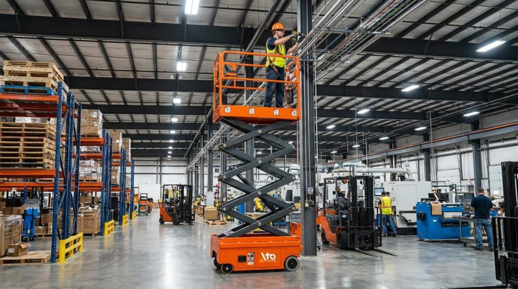
Scissor lift stability is the result of geometry, load physics, and disciplined operating practices working together. This guide explains how the structure, powertrain, and center of gravity control affect tipping margins so you can answer “how stable are scissor lifts” with engineering facts, not guesswork. You will see how static, dynamic, and edge loading change risk, and what operators must do daily to keep platforms inside their safe stability envelope. Use it as a practical reference for specifying equipment, training teams, and managing a safer scissor platform fleet.
How Scissor Lifts Achieve And Maintain Stability
Stability envelope and tipping mechanics
When people ask “how stable are scissor lifts,” the correct answer is: they are very stable inside their designed stability envelope and quickly unsafe once you push loads or wind beyond that boundary. The stability envelope is the 2D “footprint” inside which the combined center of gravity (CG) of lift plus load must stay to avoid tipping. Engineers define this as a polygon based on wheel or outrigger contact points, then apply safety factors for wind, motion, and platform height. Understanding this envelope is the foundation for safe setup and loading.
| Concept | What it means | Key influence on stability |
|---|---|---|
| Support polygon | Area between wheels/outriggers in plan view | Wider/longer base = larger tipping margin |
| Center of gravity (CG) | Resultant position of lift + load weight | Must stay inside support polygon for stability |
| Overturning moment | Torque trying to rotate lift about an edge | Increases with height, offset load, and wind |
| Resisting moment | Torque from lift weight acting within base | Higher own-weight and wider base increase it |
| Stability factor | Ratio of resisting to overturning moment | Design and standards require minimum values |
Horizontal load shift, wind, or platform movement all act by moving the CG toward one edge of the support polygon. The lift tips when the CG passes directly above a wheel line or outrigger line and the overturning moment exceeds the resisting moment from the remaining support points. This is why standards and manuals insist on level ground, controlled loading, and wind limits.
How engineers calculate CG and load effects
Engineers break the structure into elements and sum their contributions to find the CG. A typical approach uses weighted averages of component loads and positions. For a simplified two-leg model, the combined CG location in one direction can be expressed as a load-weighted position of each leg. A common formulation is CG = (x1 × W1 + x2 × W2) / (W1 + W2), where x1 and x2 are distances from a reference point, and W1 and W2 are the loads on each leg. Engineers use this same principle with more elements to locate the true CG of the lift and its load. Once they know the CG, they calculate overturning moments about each potential tipping edge and compare them to resisting moments to define the stability envelope.
Within that envelope, a scissor lift behaves predictably and stays upright under normal operating disturbances. Outside it, even a small extra push from wind or a worker leaning out can be enough to cross the tipping line.
Static, dynamic, and edge loading basics

“How stable are scissor lifts” also depends strongly on how the load is applied: static, dynamic, or concentrated at the edge. These three loading modes change both the stress in the mechanism and the stability margin, even if the total weight is the same. Understanding the differences helps operators keep real-world use inside the engineering assumptions.
| Load type | Simple definition | Typical examples | Stability impact |
|---|---|---|---|
| Static load | Weight applied without significant motion | Person standing still; pallet placed and left in position | Closest to rated capacity assumptions; highest stability |
| Dynamic load | Load that moves, accelerates, or impacts | Rolling a pallet truck on; sudden braking; jumping on deck | Short-term higher forces and CG shifts reduce margin |
| Edge load | Weight concentrated near platform perimeter | Heavy item set near guardrail; worker plus materials at one corner | Increases bending and leg forces; moves CG toward tipping edge |
A static load is the baseline case: weight applied and held without motion. Manufacturers rate static capacity in force units and validate it with controlled tests according to internal or regional standards. Static loads match how engineers check stresses and deflections in the structure.
Dynamic loads occur whenever the load moves or impacts the platform, such as rolling a pallet truck on, starting or stopping travel, or a worker walking quickly and then stopping. These motions introduce inertia forces that add to the static weight. To cover this, engineers apply dynamic factors above the nominal static rating so that short spikes in force still remain within material and stability limits. That is why sudden movements are discouraged even when the total weight is under the nameplate rating.
Edge loading is especially critical for tipping risk. When weight sits near the platform perimeter instead of being uniformly distributed, bending moments in the deck and forces in the outer scissor legs and pins rise significantly. Technical data for industrial lift tables often specify separate edge-load or end-load limits for this reason. At the same time, the CG shifts toward the platform edge, shrinking the distance to the tipping line.
- Keep heavy items as close to the platform center as practical.
- Avoid stacking dense loads at one side or one corner.
- Limit rolling loads and sudden stops at height.
- Respect any published edge-load or point-load limits, not just total capacity.
Loading patterns also affect how forces travel through the scissor legs and into the ground. Rolling loads can create localized deflection in specific legs, while sliding or shifting loads apply transient side or end forces. If these movements push the CG close to the support polygon boundary, the safety margin against tipping drops. Proper practice keeps the CG inside the manufacturer’s defined stability polygon at all times.
Why “under capacity” can still be unsafe
Even if the total weight is below the rated load, a lift can become unstable if the load is dynamic or poorly positioned. A concentrated edge load may satisfy the nameplate capacity but still overstress the deck or move the CG dangerously close to a tipping edge. Similarly, a fast-moving worker or rolling equipment can create dynamic peaks well above the static rating. From an engineering perspective, the safe answer to “how stable are scissor lifts” is: stable when weight, motion, and position all stay within the tested envelope, not just when the scale reading is under the limit.
Engineering Factors: Geometry, Loads, And Powertrain
Engineering design determines how stable are scissor lifts under real-world loading, not just in theory. This section links geometry, load paths, and powertrain behavior to tipping margins and structural life so you can match equipment to the job, not guess.
Scissor geometry, CG, and load distribution
Scissor kinematics, center of gravity (CG), and leg loading work together to define the actual stability envelope. When any of these shift unfavorably, the platform may still feel solid but operate with very low tipping margin.
- Leg forces rise sharply as the lift approaches full height because the scissor angle flattens and mechanical advantage drops.
- Off-center loading shifts the combined CG toward one edge, reducing the distance to the tipping line.
- Uneven ground or tire sinkage tilts the base, moving the CG closer to a corner and increasing overturning moment.
- Good engineering practice keeps the combined CG well inside the support polygon for all rated load cases.
Key formulas engineers use for CG and leg loading
Designers use simplified relationships to size pins, legs, and cylinders and to answer “how stable are scissor lifts” for a given duty cycle.
| Concept | Representative formula | Main use |
|---|---|---|
| Leg load distribution | W = (L1 + L2) / 2 | Estimate total load carried by adjacent scissor elements for preliminary sizing based on scissor geometry |
| Center of gravity position | CG = (x1 × W1 + x2 × W2) / (W1 + W2) | Locate combined CG along a reference axis from loads on different legs or supports for stability checks |
| Moment arm of load | MA = (x1 × W1 + x2 × W2) / (W1 + W2) | Evaluate overturning moments about the CG or a tipping edge under different loading patterns |
These relationships feed into more detailed analytical or numerical models to evaluate leg axial forces, pin shear, and base reactions for worst-case static, dynamic, and edge loads.
Engineers then relate CG position to the base “stability polygon” formed by the wheel or outrigger contact points. As long as the vertical projection of the combined CG stays inside this polygon with margin for wind and dynamic effects, the lift remains stable.
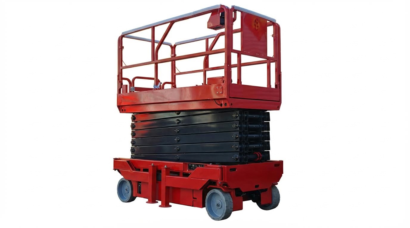
Platform size, height, and single vs. double scissor
Platform geometry and lift height strongly influence how stable are aerial platforms across their working envelope. Bigger and taller is not automatically better; both increase overturning leverage if the load shifts.
| Factor | Engineering influence on stability | Practical implications |
|---|---|---|
| Platform size (length × width) | Controls how the applied load spreads into the deck and legs. A larger deck improves usable area but allows the load CG to move further from the center, increasing overturning moment at the base if operators work at the extreme edge | Keep heavy material away from corners and avoid cantilevering loads beyond the deck edge. Longer platforms may need stricter edge-load limits. |
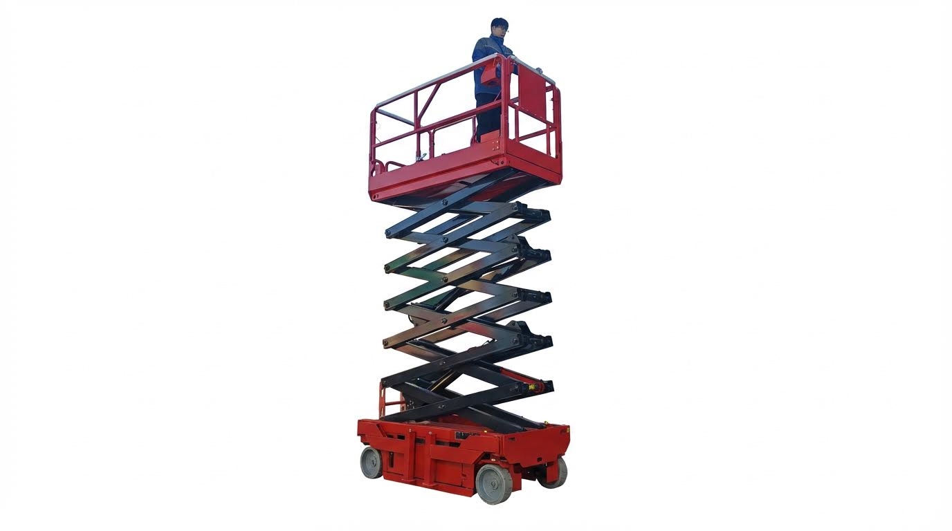
| Height / travel | As height increases, leg slenderness and lateral deflection grow, which reduces stiffness and increases sway. Base width and leg section modulus must offset this to keep lateral drift within safe bounds. | At maximum height, follow wind limits strictly and avoid side loading. Some compact models are very stable at mid-height but more sensitive at full extension. |
| Single-scissor configuration | Uses one X linkage. Suits moderate heights with simpler kinematics but develops high leg compression and bending at full stroke, which can reduce stiffness and stability if under-designed at tall working heights | Best for low to mid-height tasks where compact stowed size matters more than maximum reach. |
| Double-scissor configuration | Stacks two X linkages. Achieves greater travel with more favorable leg angles and improved stiffness at full height compared with very tall single-scissor designs | Preferred for higher working heights when you need better rigidity and reduced sway, at the cost of more components and weight. |
Load patterns: uniform vs. edge loading
Beyond total capacity, the way the load sits on the deck changes structural demand.
- Uniform / central load – Closest to catalog ratings. This is the basis for most “static load” capacity values used in specifications.
- Dynamic load – Occurs when rolling on with a pallet truck or when the platform starts, stops, or bounces. Engineers apply safety factors above nominal static ratings to keep stress and deflection within limits during these events.
- Edge / end load – Weight concentrated near the perimeter raises deck bending moments and leg forces, especially in the outer legs and pins so many industrial tables specify separate edge-load limits.
To maintain stability and structural life, treat catalog capacity as valid only for the manufacturer’s defined loading pattern and keep high-mass items toward the center of the deck.
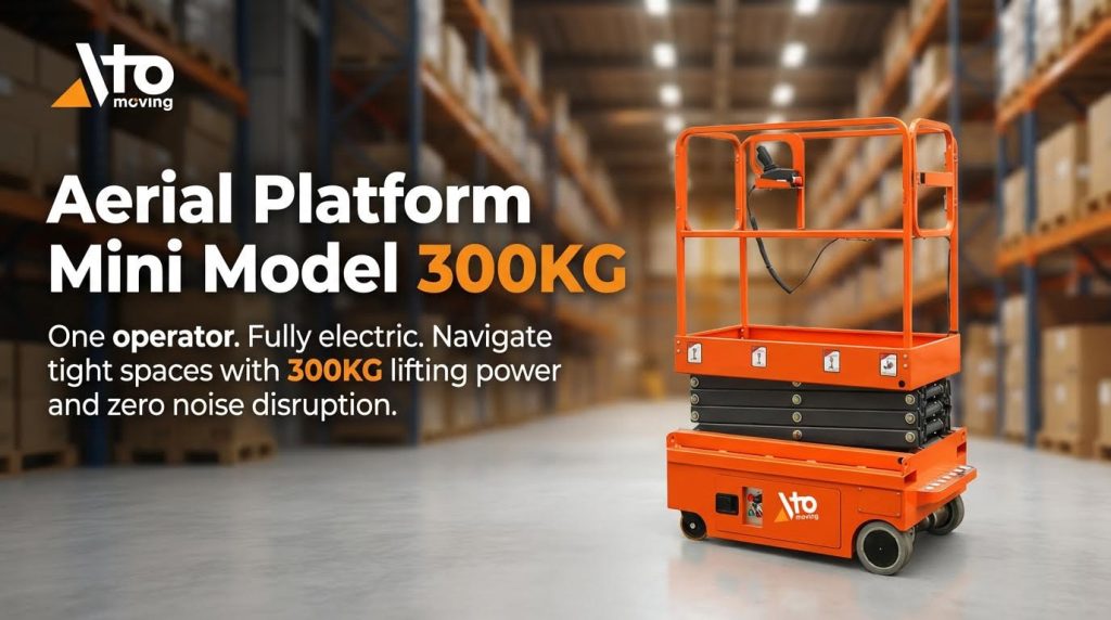
Hydraulics, electric drives, and structural analysis
The powertrain does not just lift the platform; it also influences how stable are scissor platform lifts under changing loads, especially near full height. Cylinder or screw stiffness, control strategy, and structural design together determine how the system reacts to shock, wind, and operator inputs.
| System / method | Engineering behavior | Impact on stability and control |
|---|---|---|
| Hydraulic driveline | Converts pump pressure into cylinder force, which multiplies through the scissor geometry. Load capacity depends on pressure, cylinder bore, and mechanical advantage. Overload valves limit maximum force to protect structure while typical positioning accuracy is about ±5 mm. | Hydraulic compliance (oil compressibility, hose stretch) can allow small oscillations under sudden load changes. Correct valve tuning and maintenance keep motion smooth and predictable. |
| Electric driveline | Uses electric motors with screw or linkage mechanisms, removing hydraulic fluid and hoses. These systems offer high stiffness with minimal compliance and very repeatable positioning for a given load. | Higher mechanical stiffness reduces bounce and drift under changing loads, which improves operator confidence and makes small platform movements easier to control near delicate work. |
| Power system reliability | Hydraulic units rely on clean fluid, sound hoses, and healthy seals to maintain rated force and motion accuracy while modern electric units often use long-life batteries to support uptime. | A degraded powertrain may not lift smoothly or may stall unexpectedly, which can startle operators and contribute to unsafe reactions, even if structural stability is technically adequate. |
Structural calculations and FEA in scissor lift design
To validate stability and durability, engineers combine hand calculations with numerical models.
- Theoretical calculations – Classical mechanics models define lift force, leg compression, and pin shear for different cylinder layouts and loading conditions and guide early material selection and carrying capacity estimates.
- Finite element analysis (FEA) – Detailed models apply loads at key points on the scissor arms and deck to map stress and deflection and compare results with theoretical predictions.
- Stability verification – Engineers confirm that, for all rated load cases, the reaction forces at each wheel or outrigger stay positive and the overturning moment never exceeds the restoring moment with required safety factors.
This combination of analytical and numerical work answers the core design question: under which loading, height, and wind combinations does the lift remain safely inside its stability envelope, and with how much margin.
When geometry, loading rules, and powertrain behavior are all respected, modern designs maintain high stability margins for their intended use. Most tip-overs occur not because the mechanism is inherently unstable, but because real-world loading or operating conditions push the system beyond the engineered envelope.
Operator Practices, Standards, And Fleet Management
Pre-use checks, ground conditions, and positioning
Operator behavior and setup conditions often decide in practice how stable are scissor platform, even when the design is sound. Consistent pre-use checks and disciplined positioning keep the center of gravity inside the stability envelope and prevent surprise failures.
Before every shift, use a structured pre-operation checklist to catch defects and instability risks early.
- Walk-around inspection: leaks, damage, missing pins, loose components, warning labels.
- Hydraulic system: check fluid level and look for hose leaks or abrasion. Power system reliability depends on clean fluid and leak-free cylinders.
- Electric system: verify battery charge, cables, and any onboard diagnostic alerts. Standardized pre-operation inspections reduce mid‑shift breakdowns.
- Guardrails and gates: confirm full height, secure fasteners, and correct operation of gates and toe boards.
- Controls: test lift, drive, steering, emergency stop, and emergency lowering functions from both ground and platform controls.
- Wheels/tires: inspect tread, damage, and inflation where applicable.
Ground and surface conditions directly affect how stable are scissor platform lift at height. A marginal surface can turn a small side load into a tip-over.
- Assess ground bearing: avoid soft soil, trenches, voids, or recently backfilled areas. Use cribbing or mats if bearing capacity is uncertain.
- Match lift type to terrain: use rough-terrain units outdoors; reserve slab models for flat, hard, level floors. Ground stability assessment before setup is mandatory.
- Level the chassis using built-in leveling or outriggers where provided, then recheck bubble levels or inclinometer.
- Never use blocks or makeshift supports under wheels or outriggers.
Positioning strategy must protect both stability and people around the machine.
- Keep at least 10 ft (3 m) horizontal clearance from power lines and energized conductors. OSHA requires minimum approach distances to electrical sources.
- Set up away from drop-offs, loading dock edges, pits, or ramps that could cause sudden tilt.
- Implement traffic control: cones, barricades, and signage to keep forklifts and trucks away from the base.
- Use a ground guide when moving in tight or congested areas. Guides are recommended when operating near large objects or power sources.
- Do not move the lift while elevated unless the manufacturer explicitly permits it under defined conditions; even then, keep speed very low and surface smooth. Mobile lifts should not exceed about 1 ft/s and should avoid debris at height.
Why these practices matter for stability
Thorough checks reduce the chance of hydraulic or structural failure at height. Ground and positioning errors often shift the effective center of gravity toward an edge, shrinking the stability polygon and making a side load or gust more critical. Good habits here are the cheapest way to improve how stable are scissor lifts in real jobs.
OSHA/EN rules, guardrails, and fall protection
Regulatory standards define the minimum conditions under which scissor lifts are considered acceptably stable and safe. They connect load ratings, guardrail design, and operating rules into a single system.
OSHA and EN rules for scissor lifts focus on three pillars: rated capacity, documented procedures, and hazard controls.
- Rated load, maximum platform height, and allowable occupants must be clearly marked on the machine and never exceeded. Standards require compliance with these ratings during operation.
- Equipment must safely support at least four times the maximum intended load plus its own weight to prevent collapse. Load capacity compliance is a core requirement.
- Facilities must maintain documented pre-use inspections, defect lockout procedures, and maintenance records.
- Only trained and authorized employees may operate the lift, with training covering operation, hazards, and load limits. OSHA assigns this training duty to employers.
Guardrails and fall protection directly influence both perceived and actual answers to the question “how stable are scissor lifts” for people working at height.
| Guardrail / Fall-Protection Element | Key Requirement | Stability / Safety Impact |
|---|---|---|
| Top-rail height | Approx. 42 in above platform, ±3 in tolerance; must not deflect below 39 in under load Guardrail technical specifications | Prevents falls while allowing normal work posture. |
| Impact resistance | Withstand at least 200 lb applied within 2 in of top edge without failure Guardrail impact criteria | Absorbs worker contact without collapse or major deflection. |
| Use rules | Workers must stand on the platform, not on rails; no leaning or climbing OSHA scissor lift guidance | Prevents CG from shifting outside the guardrail envelope. |
| Fall-arrest PPE | Harness and lanyard used where risk assessment or local rules require it Fall protection guidance | Secondary protection if a worker slips or guardrail is bypassed. |
Environmental limits also play a major role in stability.
- Follow manufacturer wind ratings; many units should not be used outdoors above roughly 28 mph wind speed. OSHA highlights wind-speed limits and storm conditions.
- Do not operate in storms, strong gusts, or where wind funnelling between buildings can create local peaks.
- Never add tarps, sheeting, or large panels that act as sails; they dramatically increase overturning moments.
- Do not move the platform at height during high winds; one documented tip-over occurred around 39 ft in gusts over 50 mph. Incident analysis shows wind as a key factor.
How standards tie back to stability physics
Load-rating rules keep the combined weight and dynamic effects within the design’s stability polygon. Guardrail strength and height limit how far a worker’s center of gravity can move toward an edge. Environmental and movement limits cap the external forces (wind, acceleration) that can create overturning moments larger than the restoring moment from the lift’s base and counterweight.
Training, maintenance, and predictive diagnostics
Even a well-designed lift can feel unstable if operators lack training or if maintenance is reactive instead of planned. Training and fleet practices close the gap between theoretical stability and what actually happens onsite.
Operator and supervisor training should cover both “button pushing” and the underlying physics of how stable are scissor lifts.
- Eligibility: only trained and authorized workers may operate scissor lifts. OSHA specifies training and authorization requirements.
- Core topics: vertical and travel operation, emergency controls, material handling within weight and footprint limits, and recognizing unstable ground.
- Hazard recognition: fall risks, electrical contact, falling objects, and tipping due to overloading or side loading. Standards require training on these hazards.
- Reporting culture: operators must know how and when to report defects, unusual motions, or warning lights, and must feel empowered to tag out equipment.
Maintenance strategy has a measurable impact on stability, uptime, and fleet cost.
| Maintenance Layer | Typical Actions | Stability / Uptime Benefit |
|---|---|---|
| Daily preventive checks | Visual inspection, fluid levels, battery charge, tire condition, guardrail and control tests Preventive maintenance extends life and validates safety devices | Catches leaks, misalignment, or control faults before they compromise stability at height. |
| Weekly / monthly PM | Lubricate pins, inspect welds for cracks or corrosion, verify emergency lowering, check drive systems Scheduled tasks keep structure within design tolerances | Maintains stiffness and predictable motion, reducing sway and unexpected deflection. |
| Battery management | End-of-shift charging, avoiding deep discharge, checking water levels on flooded batteries Structured charging prevents mid‑shift shutdowns | Prevents power loss or sluggish response when elevated, which can feel like instability. |
Predictive diagnostics and data-driven fleet management push stability and availability even further.
- Onboard diagnostics monitor sensors, pressures, and controller faults to detect anomalies early. Newer platforms use connectivity for predictive maintenance.
- Remote connectivity allows fleet managers to see error codes, usage hours, and overload events in real time.
- Trend analysis (e.g., repeated overload alarms or tilt warnings) highlights operators or locations that systematically stress stability limits.
- Planned interventions replace parts (hoses, pins, batteries) before they fail under load, reducing both downtime and safety incidents.
Key Takeaways For Safer, More Stable Scissor Lift Use
Scissor lift stability comes from three pillars working together: sound engineering, controlled loading, and disciplined operation. Geometry, support polygon, and center of gravity define a hard stability envelope. Hydraulics or electric drives, structural sizing, and safety factors then keep the machine predictable inside that envelope. When you respect these limits, even tall platforms operate with strong tipping margins.
Real risk appears when real work breaks the design assumptions. Dynamic and edge loads, soft ground, wind, or poor positioning can move the center of gravity toward a tipping edge long before the nameplate capacity is exceeded. That is why operators must center heavy loads, avoid sudden motion at height, follow wind and travel limits, and perform pre-use checks every shift.
For operations and engineering teams, the best practice is clear. Choose scissor lifts whose geometry, height, and drive match the task. Train every operator on basic load physics, not just controls. Lock in preventive and predictive maintenance so stiffness, braking, and control response stay within design intent. When you combine good design with strict field discipline, modern platforms from Atomoving deliver stable, repeatable performance across their full working range.
Frequently Asked Questions
How stable are scissor lifts?
Scissor lifts are designed to be stable, especially when used on flat, even surfaces. They feature a larger platform supported by an “X”-shaped crisscross mechanism that extends vertically, providing a solid base for workers and tools. However, stability can be compromised under certain conditions:
- Avoid using scissor lifts in wind speeds exceeding 25 mph, as gusts can cause instability or wobbling Scissor Lift Safety Tips.
- Never exceed the lift’s load capacity, as overloading can strain the machinery and affect stability Scissor Lift Stability Guide.
What factors affect the stability of a scissor lift?
Several factors can impact the stability of a scissor lift during operation:
- Using the equipment on uneven or sloped surfaces increases the risk of tipping.
- Weather conditions, such as strong winds, can destabilize the lift, particularly outdoors.
- Overloading the platform beyond its weight limit compromises the structural integrity of the lift Scissor Lift Stability Guide.