Scissor lifts provided controlled vertical access for construction, maintenance, and industrial tasks at height. Effective use relied on matching lift type to ground conditions, load, and environment, and on disciplined pre-use planning. Safe operation required structured inspections, adherence to rated capacity, and strict compliance with model-specific manuals and control layouts. Modern practice also integrated preventive maintenance, diagnostics, and evolving all-electric systems to improve reliability, safety, and lifecycle performance across the full range of applications described in this article.
Core Scissor Lift Functions and Applications
Core scissor lift functions centered on providing controlled vertical access with a compact footprint. Industry operators used these platforms for repetitive work at height where ladders or scaffolds increased risk or setup time. Understanding the mechanism, load paths, and application boundaries supported correct model selection and safe use. The following subsections outlined how the structure carried loads and how different environments drove configuration choices.
Vertical Access Mechanism and Load Paths
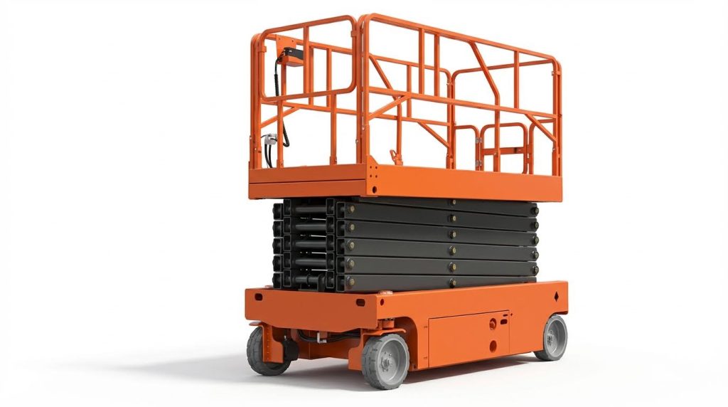
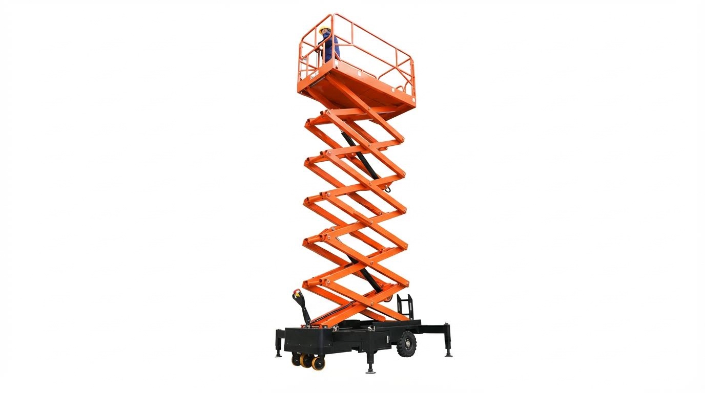
A scissor lift elevated the platform using crossed, hinged arms that formed a pantograph mechanism. Hydraulic, electric, or electro-hydraulic actuators applied force at the base of the scissor stack, converting horizontal thrust into vertical motion through the link geometry. The primary load path ran from the platform through the scissor arms, pins, and weldments into the base frame and then into the ground via wheels or outriggers. Rated load capacity included personnel, tools, and materials, so engineers sized cylinders, pins, and structural sections for combined dead load, live load, and dynamic factors. Stability margins depended on center-of-gravity location, platform height, and wheelbase, which was why manufacturers prohibited overreaching or climbing on guardrails. Guardrails and toe boards contained personnel and tools, while emergency stops and limit switches interrupted power if motion exceeded design limits.
Typical Industrial and Construction Use Cases
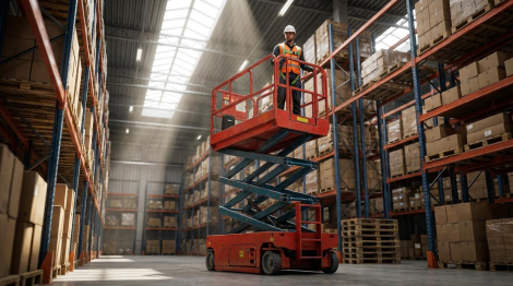
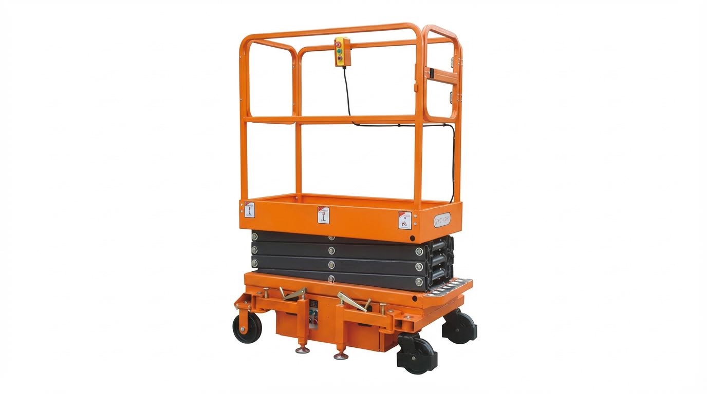
Scissor lifts supported a wide range of industrial and construction tasks requiring vertical but not horizontal outreach. Typical work included electrical installation, lighting maintenance, sprinkler piping, ductwork, and ceiling or façade finishing. Warehouses used compact electric units for order picking, rack installation, and inventory management, where low noise and zero local emissions were critical. Manufacturing plants deployed them for equipment access, line modification, and overhead utility routing, often within tight aisles. On construction sites, rough-terrain models with larger platforms handled cladding, glazing, and formwork stripping at moderate heights. Facility maintenance teams used smaller indoor units for painting, signage, and HVAC service, replacing ladders to reduce fall risk. Across these use cases, operators relied on the platform as a temporary work area, not as a material hoist, so they respected rated capacity and floor loading limits.
Indoor vs. Outdoor and Rough-Terrain Selection
Selection between indoor, outdoor, and rough-terrain scissor lifts depended on surface conditions, height, and environmental constraints. Indoor applications typically used electric scissor lifts with non-marking tires, low overall weight, and compact width to fit standard doorways and narrow aisles. These units produced low noise and zero exhaust at the point of use, which aligned with occupational exposure limits and ventilation constraints. Outdoor and rough-terrain work required higher ground clearance, larger tires, and often four-wheel drive to handle unpaved or uneven surfaces. Rough-terrain models carried higher weight and load capacities, so planners checked ground bearing capacity and slab design before deployment. Wind ratings also differed: outdoor-rated platforms allowed operation within specified wind speeds, whereas many indoor-only models required zero wind. For mixed-use facilities, engineers evaluated duty cycle, maximum required height, slope conditions, and transport limitations before standardizing on a fleet configuration.
Pre-Use Planning, Setup, and Safe Operation

Pre-use planning for scissor lifts established a structured safety envelope before elevation. Operators evaluated the task, environment, and equipment capability as a single system. This planning reduced instability, collision, and overload risks. It also aligned site practice with regulatory requirements for mobile elevating work platforms.
Site Assessment, Ground Bearing, and Stability
Site assessment started with identifying surface type, slope, and potential subsurface voids. Operators verified that the ground bearing capacity exceeded the combined weight of the lift, personnel, and tools. They avoided soft soil, trenches, service ducts, and covers that could collapse under concentrated wheel loads. On marginal surfaces, they used spreader pads or manufacturer-approved outrigger configurations to reduce ground pressure.
Stability required operating on level ground within the slope limits specified in the manual. Operators did not elevate on cross-slopes or near drop-offs, ramps, or loading dock edges. They checked for overhead power lines, building projections, and pipework that could contact the platform during travel or elevation. Cones or barriers defined an exclusion zone to keep pedestrians and vehicles clear of the lift’s footprint and swing area.
Pre-Operation Inspection and Function Tests
Pre-operation checks followed the model-specific operator’s manual and applicable standards. Operators inspected the structure, scissor arms, guardrails, and welds for deformation, cracks, or corrosion. They checked hydraulic systems for leaks, damaged hoses, loose fittings, and verified hydraulic fluid levels. Tires or tracks had to be intact, with correct inflation or tension, and free from embedded debris.
They confirmed that guardrails, gates, and toe boards were intact and latched. Function tests included raising and lowering the platform, steering, drive, and emergency stop operation from both platform and ground controls. Operators verified emergency lowering systems worked and that alarms, horns, and limit switches responded correctly. Any abnormal noise, sluggish movement, or failure to move after control input required immediate lockout and technical inspection before use.
Control Layout, Operating Sequence, and Signals
Before operation, personnel familiarized themselves with the specific control layout for that model. Control stations typically included selectors for ground or platform control, joysticks or switches for lift and drive, and clearly marked emergency stop buttons. Operators followed the startup sequence in the manual, including key switch position, brake release, and initial low-height function test. They always returned controls to the neutral or zero position before energizing the system after a power interruption.
During work, operators used smooth, incremental inputs to avoid sudden acceleration or deceleration. They coordinated with ground personnel using predefined hand signals or radios, especially when visibility was limited. Only one control station had command at a time, with transfer performed according to the manufacturer’s procedure. Clear communication minimized unintended movement while personnel worked near the chassis or under the platform.
Load Management, PPE, and Fall-Object Control
Load management started with knowing the rated platform capacity and maximum occupants from the data plate. Operators calculated the total load, including personnel, tools, and materials, and kept it below the rated limit with a safety margin. They distributed weight evenly on the platform floor and kept heavy items away from guardrail edges. No one used the guardrails as a support for ladders or as a means to gain extra reach.
Personnel wore appropriate PPE such as hard hats, non-slip footwear, and, where required, harnesses connected to approved anchor points. They kept their bodies within the guardrail envelope and did not lean or climb on rails. Tools and loose materials were secured with tool belts, lanyards, or containers to prevent dropped objects. At the end of the shift, operators fully lowered the platform, removed materials, shut off power, and parked the lift in a protected area to maintain long-term safety and equipment integrity.
Control Systems, Maintenance, and Troubleshooting
Platform and Ground Controls, E-Stops, and Interlocks
Scissor lifts used dual control stations: platform controls and ground controls. Platform controls allowed the occupant to raise, lower, and drive the unit, so they included proportional joysticks or toggle switches, a key or enable switch, and an emergency stop (E‑stop). Ground controls provided redundant command capability for pre-use function tests, emergency lowering, and recovery if the platform controls failed. Standards required mushroom-type E‑stops at both stations that latched mechanically and removed power from drive and lift circuits when activated. Interlock circuits monitored guardrail gates, tilt sensors, overload sensors, and outrigger or stabilizer position, and they inhibited lift or drive when a safety condition was not met.
Manufacturers integrated these interlocks through relay logic or programmable controllers. If the gate was open or the platform exceeded rated slope, the controller locked out elevation and illuminated fault indicators. Emergency lowering valves at the base allowed controlled descent in case of power loss, but did not bypass structural or overload protections. Operators needed to verify correct function of all controls and E‑stops during daily checks before elevating personnel. Only trained personnel were allowed to use override or auxiliary lowering features, following the specific sequence in the operator’s manual.
Hydraulic, Electric, and All-Electric Drive Systems
Conventional scissor lifts used hydraulic cylinders for vertical motion. An electric or internal combustion motor drove a hydraulic pump, which pressurized fluid to extend the cylinders and raise the platform. Flow-control and check valves limited speed and prevented uncontrolled descent if a hose failed. Drive systems were either hydraulic wheel motors or electric traction motors, depending on model and terrain rating. Electric slab lifts for indoor use typically used battery-powered DC motors for both pump and traction, which reduced noise and eliminated exhaust emissions.
All-electric designs, such as recent lithium-ion models, eliminated hydraulic circuits entirely. These units used screw drives or electric actuators, self-lubricating linkages, and integrated electronic control units with self-diagnostics. The absence of hydraulic oil removed leak risks and reduced maintenance tasks like hose inspection and fluid replacement. However, they required disciplined battery management, including correct charging profiles and temperature control, to achieve the specified service life. Rough-terrain lifts retained robust hydraulic systems with higher flow rates, larger cylinders, and oscillating axles to handle uneven outdoor surfaces while maintaining rated stability.
Inspection Intervals, PM Tasks, and Recordkeeping
Safe operation depended on structured inspection intervals aligned with standards and manufacturer guidance. Daily or pre-shift inspections focused on visible damage, hydraulic leaks, tire and wheel condition, guardrails, and full functional checks of lift, drive, steering, and E‑stops. Weekly or monthly preventive maintenance (PM) tasks included lubricating pivot points, checking hydraulic fluid levels, inspecting hoses and fittings, and verifying battery electrolyte levels and charge performance on electric units. Semi-annual or annual inspections required more detailed structural checks for cracks, corrosion, and deformation, as well as verification of tilt sensors, overload systems, and emergency lowering devices.
Recordkeeping was a regulatory expectation in most jurisdictions. Operators and maintenance technicians documented each inspection on standardized forms, noting defects, corrective actions, and dates. These records supported compliance audits and helped identify recurring issues that indicated design, application, or training problems. Fleet managers used maintenance histories to plan component replacements, schedule major overhauls, and decide end-of-life timing. Digital maintenance systems and telematics further improved traceability by logging hours, fault codes, and battery health automatically, reducing reliance on manual entries.
Common Faults, Diagnostics, and Predictive Tools
Typical faults included hydraulic leaks, platform non-movement, erratic controls, and reduced battery runtime. If the platform failed to raise after pressing the up command, technicians first checked E‑stop status, key switch position, interlock indicators, and battery or engine power. They then inspected for abnormal noise, rapid oil temperature rise, or abnormal cylinder pressure, which indicated pump or valve issues. Oil leakage at fittings or hoses required immediate shutdown, depressurization, and replacement of damaged components before returning the lift to service. Electrical faults such as blown fuses, loose connectors, or damaged
Summary of Best Practices and Future Developments
Safe and efficient scissor lift operation relied on disciplined planning, inspection, and control of operating parameters. Crews first verified ground conditions, bearing capacity, and clearances, then matched lift type to terrain, height, and indoor or outdoor use. Structured pre-use inspections covered hydraulics, structure, tires, batteries, controls, guardrails, and emergency systems, supported by model-specific manuals and formal operator training. During operation, adherence to rated capacity, correct use of PPE, and strict body positioning within guardrails minimized fall and struck-by risks.
From a maintenance perspective, daily checks, scheduled preventive maintenance, and documented records formed the backbone of fleet reliability. Technicians applied tiered intervals for lubrication, hydraulic and electrical inspection, structural review, and functional testing of emergency descent and interlocks. Diagnostics evolved from basic visual checks to data-driven approaches using onboard sensors, remote battery monitoring, and telematics, which reduced unplanned downtime and extended component life. Consistent terminology, SI units, and compliance with applicable standards supported clear communication across global operations.
Future developments pointed toward higher electrification, reduced hydraulic content, and integrated self-diagnostics. All-electric platforms with long-life lithium-ion batteries, energy recovery, and zero hydraulic oil promised lower leakage risk and simplified maintenance. Predictive analytics, cloud-connected service platforms, and digital inspection checklists improved fault detection and regulatory documentation. In practice, organizations needed to update procedures, retrain personnel, and adapt storage, charging, and disposal practices for new technologies. A balanced approach combined proven mechanical designs with emerging digital tools, ensuring that productivity gains did not compromise safety or regulatory compliance.

