Electric forklift counterweights and batteries formed an integrated stability system that governed lifting capacity, safety margins, and structural design. This article examined how counterweights and traction batteries defined the center of gravity, interacted with axles and masts, and acted as structural ballast in electric trucks. It then analyzed battery placement, chemistry, and weight engineering, including impacts on load charts, chassis design, and floor requirements. Finally, it addressed maintenance, safety, lifecycle optimization, and concluded with how to integrate counterweight and battery decisions into a coherent engineering and procurement strategy for modern fleets.
How Counterweights And Batteries Define Stability

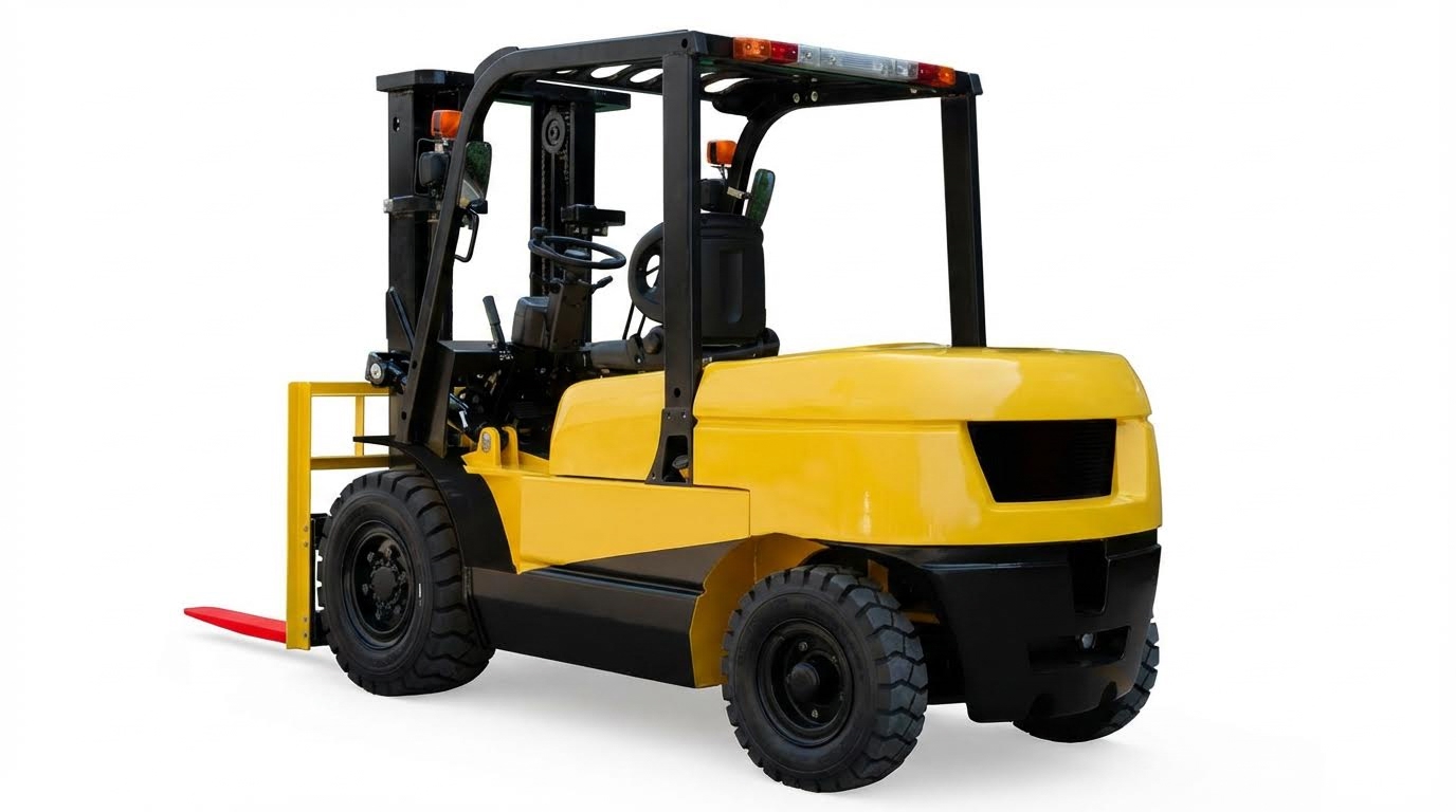
Forklift stability depended on a controlled relationship between the load, the chassis, and the rear counterweight. Electric models added the traction battery as an engineered mass that interacted with the dedicated counterweight. Designers treated the truck as a lever system, where geometry and weight distribution determined safe capacity. Understanding this interaction allowed engineers and safety managers to predict behavior under dynamic conditions such as braking, turning, and mast tilting.
Counterbalance Physics And Center Of Gravity
Counterbalance forklifts operated as class‑1 levers, with the front axle acting as the fulcrum. The combined center of gravity (CoG) of truck and load had to remain within the stability triangle formed by the front wheels and the pivot of the steer axle. When the load moved forward or the mast tilted, the CoG shifted toward the front axle, increasing the tipping moment. Designers therefore placed heavy counterweights at the rear and kept batteries and major components low to reduce CoG height. Standards and load chart calculations assumed that up to 80% of the combined truck‑plus‑load weight could sit on the front axle at rated capacity. If rear axle load dropped below roughly 20%, steering control and lateral stability degraded, especially on wet or uneven floors.
Interaction Of Mast, Load, Axles, And Rear Mass
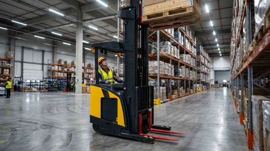
The mast assembly, carriage, and forks created a forward moment that increased with load weight, load center distance, and lift height. As operators raised the mast, the CoG moved upward and slightly forward, shrinking the stability margin and increasing the risk of longitudinal tip‑over. Rear counterweights and traction batteries compensated by generating an opposing moment about the front axle. Engineers tuned this balance so that, at rated load and specified load center, the rear axle still carried at least 20% of the total weight. Dynamic factors such as braking, acceleration, and cornering further shifted loads between axles, so manufacturers validated designs with worst‑case scenarios, including full-height lifts, mast tilt, and emergency stops. Incorrect operator practices, like adding people or loose weights to the rear, disrupted these validated conditions and violated safety regulations.
Battery Mass As Structural Ballast In Electric Trucks
In electric counterbalance forklifts, the traction battery formed a major portion of the rear mass and acted as structural ballast. Designers located large lead‑acid packs under the operator’s seat or along the chassis base to keep the CoG low and rearward. A typical 48 V, 600 Ah battery could add roughly 700 kg at the rear, enabling a 3,000 kg capacity truck to maintain its stability triangle with heavy loads. High‑voltage packs (80 V and above) often extended across the full chassis width, integrating with the counterweight casting. When fleets retrofitted from lead‑acid to lighter lithium‑ion batteries, the reduced mass (often 30–50% lower) required careful reassessment of load charts and, in some cases, supplemental counterweighting. Standards and OEM documentation therefore treated battery weight as a critical parameter in capacity ratings and stability testing.
Battery Placement, Type, And Weight Engineering
Battery engineering in electric forklifts linked structural stability with energy storage. Engineers treated the battery as both a traction power source and a calibrated counterweight. Placement, chemistry, and mass directly influenced center of gravity, axle loading, and safe rated capacity. Sound design required tight coordination between battery selection, chassis geometry, and load chart development.
Under-Seat Vs Rear-Mounted Battery Locations
Under-seat battery placement located mass low and near the truck’s longitudinal center. This configuration typically lowered the center of gravity by about 0.4 m compared with rear mounting, which improved stability during high lifts and braking. Counterbalance electric forklifts often placed 48 V or 80 V traction batteries beneath the operator platform, using the pack as part of the rear ballast system. High-voltage packs sometimes extended across the full chassis base, while smaller 24 V units could sit behind the seat when counterweight requirements allowed. Engineers had to balance accessibility for swaps and maintenance with mast clearance, cable routing, and protection from impact or debris.
Lead-Acid Vs Lithium-Ion: Energy Density And Mass
Lead-acid traction batteries historically provided 30–50 Wh/kg, which resulted in high mass for a given capacity. A 48 V 600 Ah lead-acid pack could occupy around 100 L and weigh several hundred kilograms, contributing significantly to counterbalance. Lithium-ion packs delivered roughly 150–200 Wh/kg, achieving identical or higher capacity in about 70–80% of the volume and at 30–50% lower mass. For example, a 36 V 600 Ah lithium pack of about 900 kg could match the runtime of a 36 V 400 Ah lead-acid pack weighing roughly 1,600 kg. This higher energy density allowed more compact battery compartments or integration of auxiliary devices, but designers then had to compensate for the reduced ballast effect through dedicated counterweights or revised chassis geometry.
Battery Weight Effects On Capacity And Load Charts
Battery mass directly entered the stability calculations that defined a forklift’s rated capacity. Load charts assumed a specific battery weight to maintain at least about 20% of the combined truck-plus-load weight on the rear axle at maximum rated load. Heavy lead-acid batteries between roughly 450 kg and 1,350 kg often acted as structural ballast, but they also shifted stability thresholds and could reduce effective capacity at high mast heights. When fleets retrofitted lighter lithium-ion packs, the center of gravity moved forward, which could either reduce or, with redesigned counterweights, recover 10–15% of capacity compared with suboptimal lead-acid setups. Engineers needed to recalculate derating curves, moment arms, and allowable load centers whenever battery mass changed, and update nameplates and documentation to remain compliant with safety regulations.
Chassis, Floor, And Compartment Design Constraints
Battery compartments required reinforced structures capable of withstanding at least twice the battery weight, in line with typical safety guidance. Designers integrated welded steel enclosures, retention brackets, and lockout mechanisms to prevent movement or door opening during operation. Lead-acid installations needed corrosion-resistant trays, drainage, and ventilation ducts to manage gases and spills, while sealed lithium-ion packs instead incorporated thermal sensors and wiring channels for Battery Management Systems. The mass of large packs, which could exceed 1,000 kg, also drove facility design, including minimum concrete slab thickness of about 150 mm at 27.6 MPa compressive strength for heavy traffic zones. Chassis geometry, mast cutouts, and cable routing envelopes constrained battery footprint and height, forcing trade-offs between capacity, accessibility for side-pull or roller trays, and ground clearance for rough-floor applications.
Maintenance, Safety, And Lifecycle Optimization
Maintenance practices, safety controls, and lifecycle planning determined the real cost and reliability of electric forklifts. Traction batteries acted as both energy sources and structural counterweights, so their condition directly influenced stability and rated capacity. Engineering teams needed integrated routines that covered mechanical inspection, electrical safety, and data-driven lifecycle decisions. This section focused on how operators and fleet managers optimized battery health, minimized risk, and planned upgrades over the truck’s service life.
Traction Battery Inspection And Service Routines
Traction battery maintenance routines historically differentiated between wet lead-acid and sealed lithium-ion designs. For lead-acid packs, daily checks included verifying that discharge did not exceed about 80% of rated capacity and that connectors remained tight and undamaged. Weekly tasks covered electrolyte level checks, topping up with distilled or demineralized water after full charging, and removing corrosion from terminals and trays. Monthly routines required recording cell voltages, electrolyte density, and temperature to detect imbalance or sulfation, followed by professional inspection if deviations exceeded historical baselines. Annual service typically included insulation resistance tests on both truck and battery, charger verification against manufacturer specifications, and repair of damaged paint or coatings to prevent tray corrosion.
LOTO, Charging Safety, And Thermal Management
Safe charging and handling of traction batteries relied on strict lockout/tagout procedures. Operators powered down the truck, removed the key, and disconnected the battery before any work on cables or terminals, using insulated tools to avoid arcing. Charging areas met ventilation, lighting, and signage requirements and included fire extinguishers and water supply, with smoking and metal jewelry prohibited. For lead-acid units, operators avoided letting discharged batteries sit, limited charge currents on sealed-vent types, and equalized wet cells about once per week to control sulfate buildup. Thermal management focused on keeping battery and ambient temperatures typically below about 45°C, charging at room temperature where possible, and stopping or reducing charge rates if batteries became hot or showed leakage to prevent thermal runaway or plate damage.
Lithium-Ion BMS, Monitoring, And Predictive Tools
Lithium-ion forklift batteries depended on integrated Battery Management Systems rather than routine fluid maintenance. BMS hardware monitored cell voltages, currents, and temperatures, enforcing cutoffs for overcharge, deep discharge, and overtemperature conditions. Data logging enabled technicians to track depth-of-discharge patterns, peak currents, and thermal cycles, which supported predictive maintenance and warranty compliance. Operators still inspected housings, connectors, and harness routing for wear or damage, and ensured charging used compatible equipment and remained clear of flammable materials. Modern systems also communicated with vehicle controllers or telematics platforms, allowing fleet managers to correlate battery stress with duty cycles and adjust shift patterns, charging windows, or truck assignments before failures occurred.
Managing Lifecycle Cost And Retrofit Projects
Lifecycle cost management balanced acquisition price, usable cycles, energy cost, and infrastructure requirements. Lead-acid batteries had lower upfront cost but required watering, equalization, and often spare packs plus swap equipment, increasing labor and floor space demands. Lithium-ion options carried higher purchase prices yet reduced maintenance labor, enabled opportunity charging, and typically delivered more cycles, which lowered cost per kWh delivered over 3–5 years. Retrofit projects that replaced heavy lead-acid packs with lighter lithium units needed engineering review of counterweighting, center of gravity, and load charts to preserve compliance with rated capacities. Successful retrofits evaluated charger compatibility, electrical interfaces, and floor loading, and often combined battery changes with updates to documentation, operator training, and preventive maintenance schedules to capture the full safety and productivity benefits.
Summary: Integrating Counterweight And Battery Design
Integrating counterweight geometry and battery engineering defined the stability envelope of modern electric forklifts. Designers treated the traction battery as both an energy source and a structural ballast that closed the stability triangle between mast, axles, and rear mass. Battery placement under the seat or across the chassis floor lowered the center of gravity by several decimeters and maintained the required 20% rear axle load at rated capacity. Load charts, mast height limits, and allowable load centers all depended on the assumed battery mass and location.
The transition from lead-acid to lithium-ion changed this balance. Lithium packs occupied 20–30% less volume and weighed 30–50% less for equal kilowatt-hours, which improved maneuverability and reduced floor loading but forced recalculation of counterweight sizing and rated capacity. Future platforms increasingly used modular battery bays, adjustable counterweights, and integrated BMS data to keep stability margins within regulatory limits while enabling fast battery swaps. Predictive monitoring and telematics supported proactive management of battery temperature, state of charge, and weight distribution.
In practice, engineers and fleet managers needed to treat counterweights, batteries, and chassis as a coupled system. Any retrofit that changed battery chemistry, weight, or compartment geometry required updated capacity plates, verification against standards such as OSHA requirements, and sometimes structural reinforcement of floors and battery enclosures. A balanced perspective recognized that lighter lithium systems reduced energy consumption and maintenance yet demanded more careful stability analysis. Facilities that aligned counterweight design, battery selection, and maintenance practices achieved higher uptime, safer operation, and lower lifecycle cost across mixed fleets.