Walkie stacker capacity defined how efficiently and safely warehouses handled vertical storage and short-distance transport. This article examined typical load and lift ranges, engineering limits, and operational rules that governed safe use. It also analyzed how maintenance practices preserved rated capacity over the equipment life cycle. Using these perspectives together allowed professionals to determine how much a lift stacker could safely hold in real operating conditions.
Typical Load And Lift Capacities For Walkie Stackers
Walkie stacker capacity specifications defined the safe working envelope for warehouse handling tasks. Engineers and planners relied on these values to match equipment to load mass, storage height, and aisle geometry. Understanding typical ranges in both load and lift helped prevent over-specification or, worse, chronic overloading. This section broke down capacity bands, height capabilities, configuration differences, and how duty cycle and travel distance shaped practical use.
Common Capacity Ranges In kg And lbs
Walkie stackers typically handled rated loads between 900 kg and 2,000 kg. In imperial units this corresponded roughly to 2,000 lb to about 4,400 lb. Several product families used discrete rating steps such as 2,200 lb, 3,000 lb, and 4,000 lb to simplify selection and compliance. Heavy-duty walkie designs for double-pallet handling worked near the upper end of this band, often around 2,000 kg. Engineers always treated these ratings as maximums at the specified load center, not general guidelines. Real-world usable capacity reduced if attachments, non-standard forks, or off-center loads shifted the center of gravity.
Standard And Maximum Lift Heights In mm And inches
Typical walkie stacker lift heights ranged from about 3,655 mm to 5,400 mm. Converted to inches, this represented roughly 144 in to 213 in of elevation. Common catalog points included 4,875 mm, 4,899 mm, and 5,400 mm for straddle, counterbalance, and fork-over variants. Several series supported elevated heights around 189 in and storage use up to about 192 in. One widely referenced configuration combined a 2,500 lb capacity with a 143 in maximum lift, illustrating how lower heights sometimes paired with moderate capacities. Engineers selected mast height based on top rack elevation, clearance to sprinklers or building structure, and residual capacity at full lift.
Comparing Straddle, Fork-Over, Reach And Counterbalance
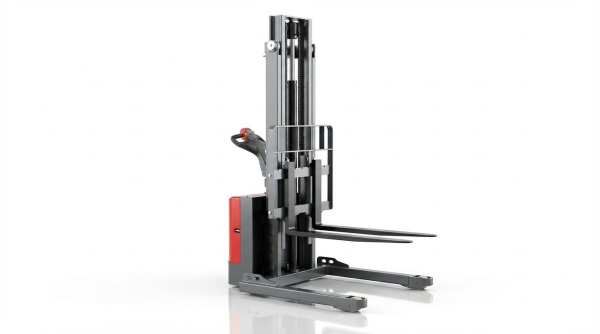
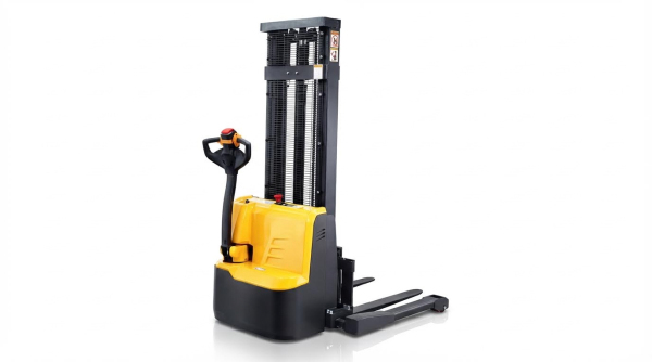
Straddle stackers used outriggers that straddled the pallet, which improved stability at height and supported lift heights near 4,875 mm to 4,899 mm. Fork-over pallet and platform stackers placed forks directly over the outriggers and typically achieved the highest lifts, up to about 5,400 mm, but required compatible open-bottom pallets. Walkie reach stackers added a pantograph or moving mast, enabling capacities around 3,000 lb at elevated heights near 189 in while working in narrower aisles. Counterbalance walkie stackers removed outriggers and relied on rear counterweight, which improved load access but usually reduced rated capacity and increased turning radius relative to straddle types. Engineers compared these architectures using stability triangles, load center diagrams, and aisle-width calculations.
Duty Cycles, Travel Distance And Aisle Constraints
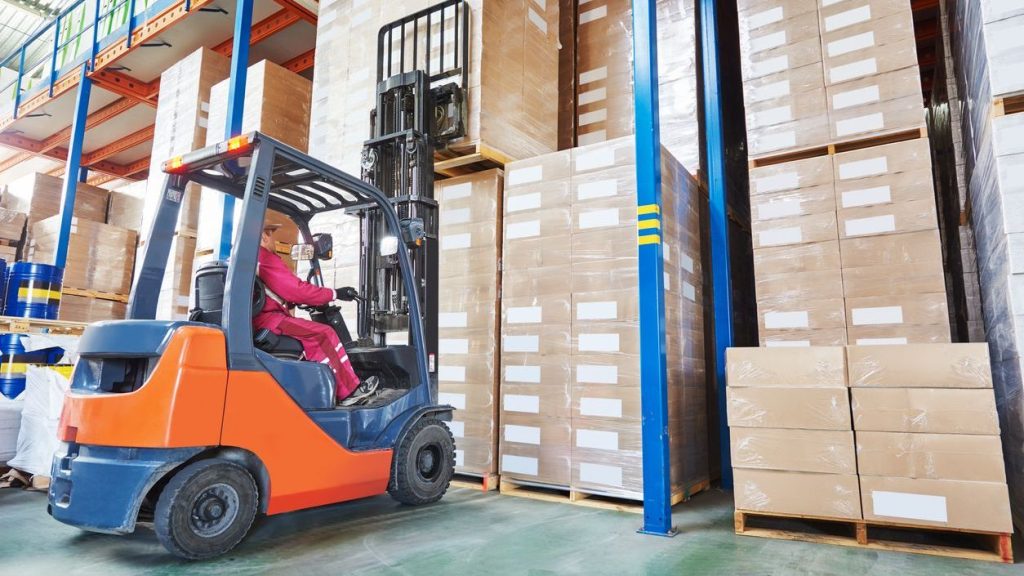
Walkie stackers operated most efficiently in short-travel, high-precision environments such as rack storage, bulk storage, and staging zones. Their typical 24 V electrical systems and compact chassis suited duty cycles with frequent lifts but limited horizontal travel distance. Narrow aisle layouts exploited the machines’ small turning radius, although extremely tight aisles constrained capacity use because operators needed reduced speed and conservative mast extension. Rated capacities assumed level floors and moderate duty; intensive multi-shift operation or long travel runs required de-rating to account for battery voltage sag, thermal limits in drive and lift motors, and increased wear. Planners therefore evaluated not only nameplate capacity and height but also cycle frequency, average travel path length, and aisle width to define realistic safe handling envelopes.
Engineering Factors That Limit Walkie Stacker Capacity
Engineering limits on walkie stacker capacity arose from a combination of geometry, structural strength, and powertrain capability. Designers balanced rated load, lift height, and stability against compact size and tight-aisle maneuverability. Actual usable capacity in a warehouse depended not only on the nameplate rating but also on the floor, slope, duty cycle, and maintenance condition of the truck. Understanding these constraints allowed engineers and operators to match stackers correctly to racking layouts, load types, and shift patterns.
Load Center, Mast Geometry And Stability Envelope
Manufacturers rated lift stacker capacity at a specified load center, typically 600 mm, using a rectangular stability triangle or polygon. As the load center increased beyond the rating point, overturning moments grew faster than counterbalancing moments, which reduced safe capacity. Higher masts with lift heights above 4,000 mm shifted the combined center of gravity upward and forward, shrinking the stability envelope at maximum elevation. Designers selected mast rail sections, chains, and tilt geometry to keep deflection, sway, and residual capacity within standards such as ISO 3691 and EN 1726. Attachments or non-pallet loads moved the effective load center and required derating calculations to maintain rollover and forward tip safety margins.
Floor Conditions, Slopes And Warehouse Layout
Rated capacities assumed operation on level, firm floors with specified friction coefficients and minimal surface defects. Uneven slabs, cracked joints, or localized settlement introduced dynamic rocking, which effectively reduced the lateral stability margin under elevated loads. On slopes above approximately 7°, the required uphill fork orientation and restricted travel height limited practical load mass to prevent loss of control. Narrow aisles and tight turn radii forced operators into sharper steering angles, which increased lateral load transfer and the risk of side tipping at higher elevations. Engineers therefore correlated capacity, wheelbase, and caster layout with minimum aisle widths, floor flatness tolerances, and permitted ramp gradients in the warehouse design.
Battery Voltage, Drive System And Duty Cycle Limits
Electric walkie stackers typically used 24 V traction batteries, and their lifting capacity depended on maintaining adequate voltage under load. As batteries discharged during the shift, voltage sag reduced pump motor speed and hydraulic pressure, which limited achievable lift height or slowed lifting under near-rated loads. Drive system sizing, including motor power, controller current limits, and gearbox ratios, constrained acceleration and gradeability when carrying maximum capacity. High-duty cycles with frequent lifts to 4,000 mm or above increased motor and hydraulic temperatures, triggering thermal protection and effectively derating capacity or lift frequency. Engineering specifications therefore defined rated capacity together with duty class, ambient temperature range, and recommended rest or charging intervals to prevent chronic overload of electrical and hydraulic components.
Safe Operation, Maintenance And Capacity Retention

Safe operation preserved walkie stacker capacity over the full service life. Operators and maintenance teams controlled real-world capacity through adherence to ratings, handling practices, and technical upkeep. Engineering limits defined the maximum, but day‑to‑day behaviors determined whether the machine actually achieved those limits. The following subsections focused on the key mechanisms that protected rated capacity and reduced failure risk.
Overloading Risks, Ratings And Nameplate Compliance
The capacity plate defined the maximum permissible load at a specified load center and lift height. Operators needed to treat this rating as an absolute limit, not a guideline, because overloads caused mast deflection, chain overstress, and structural fatigue. Overloading also triggered hydraulic pressure spikes that accelerated seal wear and increased the risk of sudden loss of lift. Safety standards required that lift stacker never carried partial loads that exceeded rated capacity at shifted load centers. Consistent nameplate compliance reduced accident probability and kept the stacker operating within its original design envelope.
Load Handling, Visibility And Travel Height Rules
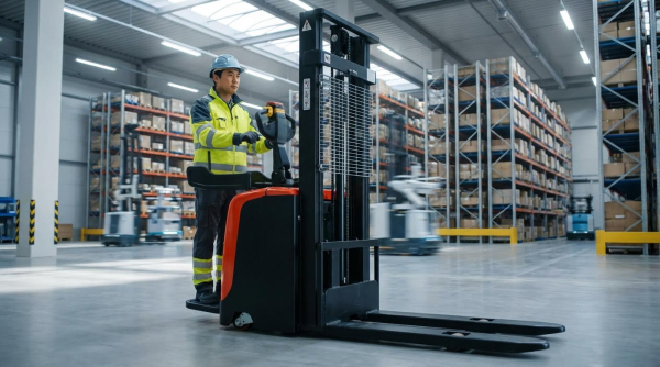
Safe load handling started with verifying that the pallet or container was stable and secure before lifting. Operators kept the load at roughly 300 mm to 400 mm above the floor while traveling on level ground to maintain a low center of gravity. Regulations and internal rules prohibited long-distance travel with forks raised above 500 mm because elevated loads reduced lateral stability and increased tip‑over risk. On slopes above 7°, the forks faced uphill when moving forward and downhill when reversing to keep the load pressed toward the mast. Clear sight lines, supported by low-profile power units and open mast designs, helped operators detect obstacles early and avoid abrupt steering corrections.
Hydraulic Oil, Seals And Valve Settings For Full Capacity
The hydraulic circuit directly governed the achievable lifting capacity at any moment. Oil volume had to match mast height, for example about 5 L for 2.5 m and up to 6 L for 3.5 m lifts, to avoid cavitation and incomplete extension. Incorrectly set overflow (relief) valves limited pressure and prevented the stacker from reaching its rated load, while excessively high settings risked hose or component rupture. Internal leakage across worn cylinder seals caused gradual load drop and reduced holding capability at height. Routine checks of oil level, contamination, seal condition, and relief valve pressure ensured that the hydraulic system could safely sustain the nameplate capacity.
Inspection, Training And Predictive Maintenance Practices
Structured inspection regimes preserved both safety and effective capacity. Daily pre-use checks verified forks, chains, wheels, and controls, while scheduled preventive maintenance addressed hydraulic, electrical, and structural elements before they degraded performance. Trained operators recognized early symptoms such as uneven lifting, slow mast response, or reduced travel power, which often indicated hydraulic leaks, low battery voltage, or drive system faults. Predictive maintenance techniques, including trend tracking of fault codes, hydraulic temperature, and battery health, allowed planners to intervene before capacity-limiting failures occurred. Combined with formal training and certification, these practices kept manual pallet jack operating close to their original design ratings over extended service intervals.
Summary: Determining How Much A Walkie Stacker Can Hold
Walkie stackers operated within their rating safely handled loads between 900 kg and 2,000 kg, with some designs supporting comparable capacities in pounds up to about 1,800 kg equivalent. Typical lift heights ranged from about 3,650 mm to 5,400 mm, with specific families such as straddle, fork-over, reach and counterbalance stackers optimized for different aisle widths, racking heights and pallet interfaces. Engineering limits arose from the stability envelope, mast and chassis geometry, load center, and the interaction with floor flatness, slopes and warehouse layout, while electrical and hydraulic subsystems constrained duty cycle and sustained capacity. These constraints meant that nameplate ratings applied only under defined conditions of load position, lift height, gradient and operating pattern.
From a safety and lifecycle perspective, the decisive factor was strict adherence to nameplate ratings and operating rules that prohibited overloading and discouraged partial loading practices that shifted the center of gravity unfavorably. Safe travel required keeping the load low, typically around 300–400 mm during movement, avoiding long-distance driving with elevated forks, and adapting speed to aisle width, surface conditions and slope, including specific uphill and downhill fork orientations above 7°. Capacity retention over time depended on maintaining hydraulic oil levels appropriate to mast height, preserving seal integrity, setting overflow valve pressure correctly, and ensuring adequate battery voltage for full lift performance. Structured inspection regimes, operator training, and predictive maintenance programs mitigated degradation from wear, electrical faults and environmental exposure, helping the stacker continue to deliver its original rated capacity.
In practice, determining how much a lift stacker could hold required more than reading the data plate. Operators and engineers had to consider the actual load dimensions, center of gravity, lift height, travel distance, slope and aisle geometry, then compare these conditions with the rated configuration. Future developments in sensor-based monitoring, on-board weighing, and stability control algorithms were expected to refine effective capacity in real time, reducing reliance on conservative manual estimates. However, even as technology evolved, the fundamental principles remained stable: respect the rated capacity, maintain the equipment to design standards, and operate within the defined stability envelope to ensure both safety and productivity.