A lifting device for transporting steel drums is shown solutions in almost every modern plant layout, from manual below-hook lifters to fully automated continuous drum elevators. This article maps that full spectrum using a structured engineering lens, starting with the core device types and progressing through design parameters, safety engineering, and standards compliance. You will see how load rating, gripping geometry, drive selection, and environmental constraints influence whether a vertical lifter, powered manipulator, or conveyor-integrated elevator fits a given duty. The closing best-practice summary consolidates these fundamentals into practical guidance for specifying, operating, and maintaining steel drum lifting systems with high safety and lifecycle performance.
Core Types Of Steel Drum Lifting Devices
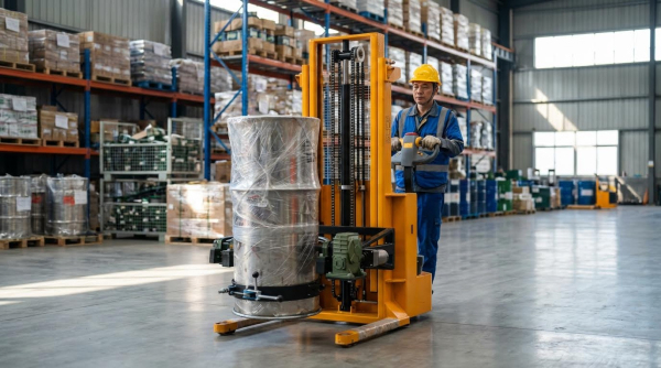
Engineering teams select a lifting device for transporting steel drums based on duty cycle, lift path, and required automation level. Each core device type addresses different constraints such as ceiling height, aisle width, and integration with conveyors or filling systems. Understanding these architectures helps match real plant constraints to safe, compliant drum handling solutions.
Vertical, below‑hook, and racker-style drum lifters
Vertical and below-hook lifters interface directly with overhead cranes or hoists to raise drums in a near-vertical attitude. Typical designs use chime clamps, radial shoes, or semi-circular cradles sized for 200 L steel drums with diameters near 560–600 mm. Engineers specify load ratings that exceed the maximum filled drum mass, which can approach or exceed 900 kg in extreme cases, while usual designs target 150–500 kg. Racker-style lifters extend this concept with articulated masts or tilting heads that place drums into horizontal rack positions for storage or decanting.
Below-hook devices must comply with ASME B30.20 and BTH-1 design categories, including defined design factors and fatigue considerations. The gripping geometry minimizes local stress at the drum chime and prevents ovalization or puncture. Mechanical balance bars or adjustable lifting eyes align the lifter’s center of gravity with the drum to reduce swing and side loading on crane hooks. These solutions suit low-throughput areas where an overhead crane already exists and where flexible, point-to-point drum positioning is required.
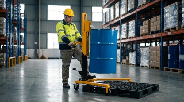
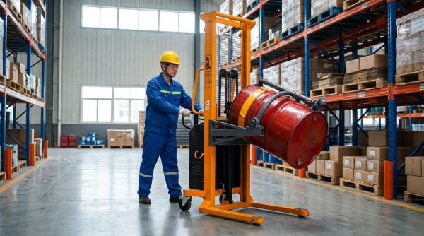
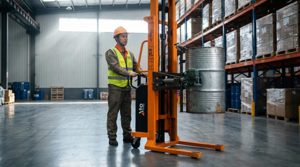
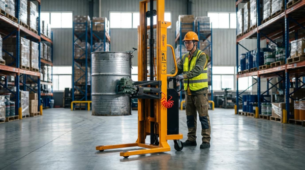
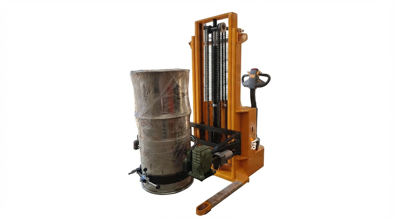
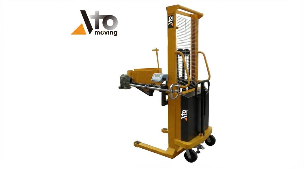
Powered drum trucks, stackers, and manipulators
Powered drum trucks and stackers provide floor-based mobility where overhead lifting is limited or unavailable. They typically use electric drive and lift, with integrated masts rated for 150–500 kg loads and lift heights from floor level up to about 3 m. Clamp heads or band-type shoes grip the drum body or chime, enabling vertical lifting, tilting, or full 360° rotation for dispensing. Engineers often select wheelbases and caster configurations to match aisle widths and turning radii in warehouses or process rooms.
Manipulators extend this concept with articulated arms or parallelogram linkages that allow offset handling, reaching into mixers, scales, or process vessels. Drive systems may be hydraulic for high torque at low speed, or electric for cleaner operation in indoor environments. Current limiters and torque control protect drums from over-clamping, especially for thinner-gauge or plastic drums. These devices support ergonomic handling by transferring the mass of a hydraulic drum stacker for transporting steel drums to the chassis, reducing operator push forces and musculoskeletal risk.
Continuous drum elevators and conveyor-integrated lifts
Continuous drum elevators act as automated vertical links between conveyor levels, mezzanines, and filling or palletizing stations. Typical systems handle 150–500 kg per carrier, with lift heights from 1 m up to 10 m or more and speeds in the 0.1–0.5 m/s range. Chain- or belt-driven platforms or clamp carriages raise drums smoothly, minimizing acceleration peaks that could destabilize liquids inside partially filled drums. Feed conveyors queue drums at the inlet, where sensors confirm position and orientation before transfer into the lift.
These systems operate as part of a continuous material flow, so control integration via PLC and HMI is standard. Safety architecture includes overload monitoring, anti-drop mechanisms, mechanical stops, and guarding or light curtains around moving elements. Noise levels typically remain below 75 dB(A) at 1 m, which supports occupational exposure limits. Engineers customize carrier geometry, infeed and discharge elevations, and accumulation logic to match upstream filling machines and downstream palletizers, delivering high-throughput solutions when a forklift drum grabber for transporting steel drums is shown as a bottleneck in line balancing studies.
Cobot-assisted and AGV-mounted drum handling systems
Cobot-assisted drum handling systems pair collaborative robots with engineered grippers to automate short-distance lifting and manipulation tasks. The cobot typically manages alignment, clamping, and tilting, while a separate lift column or small hoist provides vertical motion within a limited envelope. Force and torque sensing help maintain safe interaction with personnel and prevent over-clamping thin-walled drums. These systems suit flexible production cells where drum sizes or recipes change frequently and rapid reprogramming is valuable.
AGV-mounted drum handlers combine an automated guided vehicle or autonomous mobile robot with a mast, clamp, or platform designed for 200 L drums. The AGV transports drums between receiving, storage, filling, and shipping without manual driving, following mapped paths and traffic rules. Lift modules on the vehicle typically support loads in the 200–500 kg range and interface directly with floor-mounted stands, racks, or conveyor transfer points. When engineers evaluate a drum stacker for transporting steel drums in high-mix, high-automation facilities, cobot and AGV-based solutions enable lights-out or low-touch logistics while maintaining traceability and consistent handling forces.
Key Design Parameters And Selection Criteria
Engineering a lifting device for transporting steel drums is shown solutions requires a structured approach to design parameters and selection criteria. Engineers must align load rating, geometry, gripping method, drive technology, and environmental compliance with the actual use case. The goal is to achieve safe, repeatable handling of drums while integrating with existing material flow, including automated drum elevators and conveyor-based systems. The following subsections outline the main engineering levers that drive performance, safety, and lifecycle cost.
Load rating, drum geometry, and contents assessment
The starting point is a rigorous definition of the rated load and drum envelope. Filled steel drums typically weighed 180 to 270 kg, but 55‑gallon units could exceed 900 kg in high‑density applications, so engineers applied a conservative design basis. A continuous drum elevator, for example, operated between 150 and 500 kg per lift, which covered single or grouped drums within that range. Designers specified allowable drum diameter, usually 560 to 600 mm for standard 200‑liter drums, plus tolerances for out‑of‑round or dented shells.
Contents assessment determined not only weight but dynamic behavior. High‑viscosity liquids, slurries, or solids with shifting centers of gravity required higher safety factors and more robust anti‑swing provisions. Hazardous materials triggered additional constraints on drop prevention, leak containment, and regulatory compliance. Engineers also checked drum construction details such as chime profile, thickness, and closure type to ensure compatibility with the chosen gripping mechanism. These data fed directly into finite element checks, BTH‑1 design category selection, and hoist or cylinder sizing.
Gripping mechanisms: chime clamps, shoes, and platforms
Gripping design determined whether a lifting device for transporting steel drums is shown solutions could safely handle the full range of drum conditions. Chime clamps engaged the upper or lower rim and suited vertical, below‑hook lifters and continuous elevators where drums remained upright. Designers sized clamp jaws and pivot geometry to maintain sufficient normal force under worst‑case acceleration and tilt, while limiting local stress on the chime. For custom motorized lifters, rotating shoes with high‑friction pads provided circumferential contact and reduced risk of shell deformation.
Side‑grip shoes worked well for smaller 30‑gallon drums and for applications requiring rotation or dumping. Engineers often coupled one driven shoe with a free‑spinning shoe and added current‑limited electric actuators to prevent over‑tightening, as in devices using electric cylinders for gripping force. Platform‑type supports, including cradles or pallets, offered the most forgiving interface and accepted mixed drum materials, including plastics, at the cost of higher mass and footprint. Selection among clamps, shoes, and platforms depended on drum variability, required orientation changes, and acceptable cycle times. In all cases, designers incorporated positive retention features and “no‑drop” geometries that maintained grip even with partial power loss.
Drive systems: electric, hydraulic, and energy efficiency
Drive system selection balanced controllability, duty cycle, and energy performance. Electric drives with 3‑phase motors and chain or belt transmissions dominated continuous drum elevators and conveyor‑integrated lifts. These systems offered adjustable lifting speeds, typically 0.1 to 0.5 m/s, through variable‑frequency drives and integrated PLC control. Hydraulic drives, operating around 15 to 25 bar, provided high force density and smooth motion for compact drum manipulators, tilters, and counterbalanced stacker, especially where precise dumping torque was required.
Energy efficiency analysis considered not only motor rating but also utilization factor, acceleration profiles, and regenerative opportunities on downward travel. Engineers minimized throttling losses in hydraulic circuits by using load‑sensing pumps or proportional valves rather than fixed‑displacement units with relief throttling. For electric systems, correct motor sizing and high‑efficiency gear reducers reduced heat and extended component life. Noise levels below approximately 75 dB(A) at 1 m were achievable with well‑aligned drives and damped structures, which mattered in occupied workspaces. Integration with plant automation through PLC and HMI interfaces allowed optimization of start‑stop sequences, queue management, and interlocks to avoid idle running and unnecessary power draw.
Environmental, ATEX, and cleanroom design factors
Environmental conditions and regulatory zones strongly influenced the final configuration of a lifting device for transporting steel drums is shown solutions. For general industrial service, designers rated components for ambient temperatures between roughly −10 °C and +50 °C, with appropriate lubrication, sealing, and corrosion protection. In chemical and pharmaceutical plants, exposure to corrosive vapors or wash‑down cleaning drove the use of coated or stainless structural elements, sealed bearings, and IP‑rated enclosures. Where explosive atmospheres existed, ATEX‑compliant versions were required, which affected motor types, sensors, cable routing, and permissible surface temperatures.
ATEX or similar hazardous‑location requirements also shaped control strategies. Designers preferred intrinsically safe circuits, non‑sparking materials at potential impact points, and mechanical anti‑drop devices that did not rely solely on powered actuators. For cleanroom applications, particle generation and cleanability dominated. Engineers minimized horizontal ledges, selected low‑shedding belts or chains, and specified finishes that tolerated frequent disinfecting. All environmental variants still had to maintain core safety functions such as overload protection, emergency stops, and guarding or light curtains around moving drums. The selection process therefore linked process classification, cleaning regime, and hazard analysis directly to materials, components, and protective systems in the drum lifting device.
Safety, Standards, And Maintenance Engineering
Engineering a lifting device for transporting steel drums is shown solutions in incident statistics and safety codes. Designers must align structural, control, and guarding concepts with established regulations while enabling predictable maintenance. This section links device architecture with ASME, OSHA, and PHMSA requirements, then translates them into rigging, inspection, guarding, and lifecycle engineering practices.
Applicable codes: ASME B30.20, BTH-1, OSHA, PHMSA
Engineers specified steel drum lifting devices under ASME B30.20 for below-the-hook lifting devices and ASME BTH-1 for design criteria. BTH-1 defined design category, service class, minimum factors of safety, weld qualification, and proof-test levels for clamps, shoes, and platforms. OSHA regulations governed crane, hoist, and powered industrial truck interfaces, including inspection intervals, operator training, and lockout/tagout. PHMSA rules addressed the transported drum as a hazardous materials package, so the lifting solution could not compromise UN/DOT performance by deforming chimes, puncturing shells, or defeating closures. For automated drum elevators and conveyor-integrated lifts, control systems followed functional safety principles, with emergency stops, interlocks, and guarding designed to satisfy OSHA machine guarding requirements and applicable electrical codes.
Rigging, inspection intervals, and “no-hang” conditions
Rigging for steel drum handling relied on positive engagement of the drum chime or body, with slings and hooks sized for the combined mass of drum, contents, and lifting device. Engineers specified daily pre-use checks, monthly functional inspections, and annual comprehensive inspections, with shorter intervals for high-duty or corrosive-service equipment. Inspection scopes covered spreaders, clamps, shoes, load-bearing welds, chains, wire ropes, brakes, limit switches, and structural deformation, using non-destructive tests where required by BTH-1 or internal standards. “No-hang” rules prohibited lifting when drum mass or center of gravity was unknown, rigging was visibly damaged or improperly seated, packaging was loose, or personnel were present in the fall zone. For continuous drum elevators, controls prevented starts with uncleared faults and inhibited operation when overload, overspeed, or anti-drop devices detected unsafe conditions.
Guarding, interlocks, and emergency stop architecture
Guarding strategies for a lifting device for transporting steel drums is shown solutions in risk assessments that considered crush, shear, and impact zones. Designers used fixed guards around chains, sprockets, and pinch points, and installed interlocked doors or light curtains at drum infeed and discharge points on automated elevators. Interlocks forced the machine into a safe state when an access point opened, typically by removing the safety relay enable signal to drives and valves. Emergency stop architecture followed a fail-safe concept, with hardwired, mushroom-head E-stops located at operator stations, in travel paths, and at maintenance access points. Circuits used redundant channels and monitored safety relays so a single fault did not defeat the stop function. For powered drum trucks, counterbalanced stacker, and manipulators, deadman controls, travel speed limits, and tilt limits reduced the risk of tip-over or uncontrolled movement during transport and dumping.
Predictive maintenance, digital twins, and lifecycle cost
Maintenance engineering for drum lifting devices increasingly used condition-based and predictive strategies instead of purely calendar-based schedules. Sensors monitored motor current, hydraulic pressure, vibration, and cycle counts on clamps, cylinders, and hoist drives to detect wear before functional failure. Digital twin models of continuous drum elevators and AGV-mounted systems simulated load spectra, duty cycles, and temperature profiles, allowing engineers to refine lubrication intervals, component sizing, and inspection plans. Lifecycle cost analyses balanced capital cost against downtime, labor, and incident risk, often justifying higher-spec bearings, corrosion-resistant coatings, and modular components that reduced mean time to repair. For facilities handling hazardous materials, maintenance plans integrated PHMSA and OSHA requirements, ensuring that work on lifting devices did not compromise drum integrity, spill containment, or classified-area protections. For example, a forklift drum grabber or a electric drum stacker would require specific maintenance protocols to ensure compliance and safety.
Summary Of Best Practices For Drum Lifting Safety
A lifting device for transporting steel drums is shown solutions in a wide range of industrial settings, so safety engineering must focus on both the drum and the lifting system as a coupled unit. Steel drums often carried hazardous materials and could exceed 900 kg when filled, so uncontrolled motion or impact created high consequence events. Best practice therefore combined compliant equipment design, disciplined inspection regimes, and operator training anchored in formal procedures. Engineers also increasingly embedded automation, sensing, and interlocks into drum lifting devices to reduce human exposure while maintaining throughput.
From a design standpoint, best practice required that any lifting device for transporting steel drums was shown solutions with a documented rated capacity, verified against the heaviest credible drum mass including contents, ice formation, or residue buildup. Devices had to comply with ASME B30.20 and BTH‑1 for below‑the‑hook lifting equipment, and with OSHA and PHMSA rules where hazardous materials were present. Gripping interfaces, whether chime clamps, shoes, or platforms, needed positive engagement features that prevented release under shock, vibration, or tilt, supported by overload protection and “no‑hang” logic that stopped motion when clamps were not fully locked. For continuous drum elevators and conveyor‑integrated lifts, engineers specified anti‑drop devices, mechanical stops, and guarding or light curtains along the lift envelope.
Inspection and maintenance engineering underpinned safe lifecycle operation. Best practice defined three layers: daily pre‑use checks by operators, monthly functional inspections of brakes, safety devices, hydraulics, and controls, and annual comprehensive inspections, or more frequent where utilization was high or environmental exposure was severe. Any lifting device for transporting steel drums was shown solutions to be removed from service if deformation, cracked welds, oil leaks, or control anomalies were detected. Predictive maintenance, using sensor data on load cycles, motor current, and vibration, allowed planners to replace chains, wire ropes, and cylinders before failure, reducing unplanned downtime and incident probability.
Operationally, safe drum lifting depended on disciplined rigging and traffic control. Riggers had to determine drum mass and center of gravity, verify compatibility between drum geometry and the lifter tooling, and avoid lifting where packaging was loose, load stability was uncertain, or command signals were unclear. Loads were never allowed to pass over personnel, and exclusion zones were enforced with barriers or markings. In automated drum elevators, engineers programmed soft starts and stops, controlled acceleration, and limited lifting speeds to 0.1–0.5 m/s to avoid sloshing or tipping, especially for partially filled drums. Emergency stop circuits, designed to Category 3 or higher according to relevant safety standards, had to remove motive power while holding the load safely.
For environments with explosive atmospheres or cleanroom requirements, best practice extended to material and control selection. A lifting device for transporting steel drums is shown solutions using ATEX‑rated components, conductive wheels or grounding straps, and non‑sparking materials where flammable vapors were present. Cleanroom drum lifters used stainless steel, smooth welds, and sealed housings to allow effective decontamination and to prevent particle shedding. Across all applications, formal training, documented procedures, and periodic competency refreshers for operators and maintenance staff remained essential. As automation, cobot assistance, and warehouse order picker expanded, engineers balanced higher efficiency with rigorous risk assessment, ensuring that new technologies reduced, rather than shifted, the overall risk profile of drum handling operations.