Understanding how a pallet jack lifts is critical for specifying, operating, and maintaining equipment in modern warehouses and manufacturing plants. This article explains the full hydraulic architecture behind pallet jacks, from core components and the step‑by‑step lifting cycle to troubleshooting strategies and upgrade paths. It covers mechanical structure, hydraulic circuits, control linkages, and the physics of stability and load support. The final sections connect these fundamentals to safety standards, lifecycle cost decisions, and future trends in sensor‑enabled, data‑driven hydraulic systems.
Core Components Of A Pallet Jack System
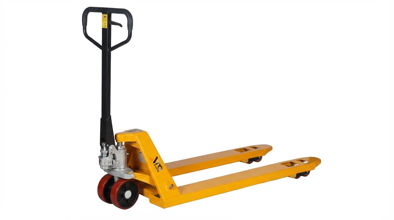
Understanding how a pallet jack lifts starts with its core components. The system combines a robust mechanical frame, a compact hydraulic circuit, and a simple but effective control interface. Each subsystem converts low operator effort at the handle into high lifting force at the forks. The interaction between these parts determines lifting capacity, stability, and service life.
Mechanical Structure: Forks, Frame, And Wheels
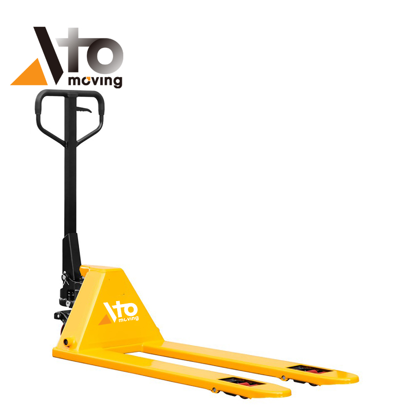
The mechanical structure carried the load and transmitted ground forces. Two tapered steel forks slid into the pallet openings and supported the load over their length, typically with a nominal lift height of about 100–200 millimetres. A welded or bolted frame connected the forks to the hydraulic unit and provided torsional stiffness so the jack stayed stable under asymmetric loads. Steer wheels at the handle end and load wheels near the fork tips shared the load and reduced rolling resistance. Polyurethane or nylon tread materials reduced floor damage and rolling friction, while hardened steel cores handled compressive stresses. This structure ensured that when the hydraulic system raised the forks, the wheels and frame kept the centre of gravity inside a safe stability triangle.
Hydraulic Circuit: Pump, Cylinder, Valves, And Fluid
The hydraulic circuit converted handle motion into lifting force. A small reciprocating pump drew hydraulic fluid from a reservoir and pushed it into a single-acting cylinder. Each pump stroke increased pressure in the closed fluid volume, forcing the piston to extend and lifting the fork carriage. Check valves maintained one-way flow into the cylinder during lifting, while a separate lowering valve created a controlled return path to the reservoir. The sealed system used low-compressibility hydraulic oil, which allowed efficient pressure build-up with minimal elastic losses. Trapped air pockets reduced effective stiffness, so operators bled air by cycling the handle without load. Proper fluid level, viscosity, and cleanliness directly affected how a hydraulic pallet truck lifts under rated capacity.
Control Interface: Handle, Linkages, And Release Lever
The control interface allowed the operator to command lifting, travel, and lowering with minimal effort. The main handle provided steering leverage and acted as the pumping lever for the hydraulic pump. Internal linkages translated handle movement into linear motion at the pump piston, setting stroke length and mechanical advantage. A three-position release lever or trigger integrated into the handle selected neutral, lift, or lower modes. In lift mode, the linkage engaged the pump and kept the lowering valve closed, so fluid flowed only toward the cylinder. In lower mode, a cam or rod opened the release valve, allowing pressurized fluid to return to the reservoir at a metered rate. The geometry and tolerances of these linkages determined how smoothly a low profile pallet jack lifted and how precisely the operator could modulate descent, especially under near-capacity loads.
Hydraulic Lifting Mechanism Step By Step
Understanding how a pallet jack lifts requires tracing the force path from the operator’s hands to the forks. The hydraulic circuit converts relatively low human input into high lifting force while keeping the load stable and controllable. Each phase, from handle stroke to controlled lowering, depends on correctly sized pistons, valves, and linkages. A clear view of these steps helps engineers optimize designs and technicians diagnose slow lifting, sinking, or erratic motion.
Force Transmission From Handle To Pump Piston
The lifting cycle starts when the operator pumps the handle through a defined arc. A pinned linkage converts this angular motion into a near-linear stroke on the pump piston. Mechanical advantage arises from lever arm ratios between the handle length and the pump pivot distance. This allows an operator to generate several hundred newtons of piston force with modest effort. The pump piston sits in a small-bore chamber, so the applied force creates relatively high fluid pressure. Check valves at the pump inlet and outlet force fluid to move in only one direction toward the main cylinder during the upstroke. Proper lubrication of handle pivots and tight clearances in the pump bore reduce energy loss and keep the lifting action smooth.
Pressure Build-Up And Cylinder Extension
Each handle stroke displaces a specific volume of hydraulic fluid into the lift cylinder. Because the fluid is nearly incompressible, this displaced volume increases pressure until it overcomes the load plus friction. The cylinder’s piston area is larger than the pump piston area, so pressure multiplies the input force and produces a higher output force on the lifting linkage. Fork elevation occurs as the cylinder rod extends and pushes on the jack’s scissor or direct-link mechanism under the frame. The lift height per stroke depends on pump displacement, cylinder area, and geometry of the linkage between cylinder and forks. If air enters the circuit, the compressible air pocket absorbs part of the stroke, causing spongy action and reduced lift height. Bleeding the system by cycling the handle under no load restores the direct pressure build-up needed for efficient lifting.
Load Support, Stability, And Center Of Gravity
Once the operator understands how a hydraulic pallet truck lifts, load placement becomes a stability question rather than just a force problem. The hydraulic cylinder supports the load through the frame and forks, but overall stability depends on the combined center of gravity of truck and pallet. Ideally, the pallet’s center of mass sits between the load wheels and as close as practical to the jack’s longitudinal centerline. This minimizes bending moments on the forks and reduces the risk of side tipping when turning. The hydraulic system must maintain pressure without significant internal leakage to prevent gradual fork sinking under static load. Excessive leakage across seals or valves shifts the effective support point over time, which can change the stability margin during storage or staging. Engineering calculations typically treat the pallet jack as a three-point support system and ensure the resultant load vector always falls within the support polygon.
Controlled Lowering And Valve Function
Lowering reverses the energy flow but still relies on precise hydraulic control. When the operator actuates the release lever, a lowering valve opens a metered path from the high-pressure side of the cylinder back to the reservoir. Gravity and load weight drive fluid out of the cylinder while the valve orifice limits flow rate to keep descent smooth. In manual units, the lever position often modulates valve opening, allowing fine control from slow creep to normal lowering speed. If contaminants or wear damage the valve seat or O-rings, fluid can bypass even with the lever in the neutral position, causing unintended sinking. In electric units, solenoid-operated valves and sometimes speed-control valves regulate lowering under electronic command. Proper valve sizing and spring selection prevent cavitation, chatter, or sudden drops, ensuring the forks track a predictable vertical path until the load rests fully on the floor.
Troubleshooting, Maintenance, And Design Upgrades

This section explains how a pallet jack lifts under real-world conditions and what happens when the hydraulic system starts to fail. It links typical symptoms to root causes, then outlines maintenance and upgrade strategies that extend service life and improve safety.
Common Failure Modes In Manual And Electric Units
When technicians investigate how a pallet jack lifts poorly or not at all, they usually find a small set of recurring faults. Manual units often lose lift because air enters the hydraulic circuit, seals harden, or the pump check valves leak. Typical symptoms include slow lifting with normal handle effort, forks that refuse to rise under load, or forks that gradually sink even with the handle neutral. Electric pallet trucks and stackers add electrical failure modes such as low battery voltage, faulty contactors, or controller faults that prevent the motor-driven pump from building pressure. In those units, slow or intermittent lifting, motor humming without fork motion, or thermal shutdowns usually indicate pump wear, clogged intake filters, or cavitation from low fluid levels. Across both types, external oil leaks at the cylinder rod, hose crimps, or fittings signal seal degradation and must be corrected before the jack loses all lifting capability.
Bleeding Air, Seal Replacement, And Fluid Care
Air trapped in the hydraulic circuit drastically reduces how a pallet jack lifts because compressible air pockets absorb pressure that should extend the cylinder. Bleeding air on a manual jack typically involves fully lowering the forks, removing all load, and pumping the handle 15–20 strokes to drive air back to the reservoir. If lifting performance does not recover, technicians inspect and replace critical seals such as the pump plunger O-ring or valve cartridge O-rings. Proper seal replacement requires safely supporting the jack, draining the fluid, cleaning all metal surfaces, and installing seals with compatible materials and correct dimensions. Fluid care directly affects pressure generation and component wear; contaminated or degraded oil causes noise, cavitation, and overheating, especially in electric units. A robust maintenance plan specifies inspection intervals, fluid change periods, ISO viscosity grade, and cleanliness targets, and always avoids mixing incompatible oil types.
Safety, Standards, And Lifecycle Cost Factors
How a pallet jack lifts also determines whether it meets applicable safety standards and internal company policies. International and regional regulations required that rated capacity, lift height, and stability margins be verified and maintained throughout the service life. Regular inspections must confirm that the hydraulic system holds the load without creeping, that the overload protection valve opens at the specified pressure, and that the lowering speed remains controlled under maximum rated load. Poorly maintained hydraulics increase lifecycle cost through unplanned downtime, damaged pallets, and potential injury claims. A cost-effective strategy compares the expense of scheduled seal kits, fluid changes, and functional tests against the replacement cost of the entire unit. Many operators adopt tiered maintenance levels, with daily pre-use checks, monthly hydraulic function tests, and annual detailed inspections documented for compliance and audit purposes.
Emerging Tech: Sensors, Telematics, And Predictive Care
Recent design upgrades changed how a pallet jack lifts and how engineers monitor its hydraulic health. Sensor-equipped units can measure lift pressure, cylinder stroke, and temperature to infer actual load, duty cycle, and fluid condition. Telematics modules transmit these parameters to fleet management platforms, which calculate remaining useful life for seals, oil, and bearings based on real usage instead of fixed time intervals. Predictive algorithms flag abnormal patterns such as increased pump run time per lift, rising oil temperature, or higher handle strokes required to reach the same fork height. These indicators allow maintenance teams to schedule seal replacements, fluid changes, or pump overhauls before lifting performance degrades or safety margins erode. For retrofit applications, low-cost pressure and position sensors combined with data loggers already deliver early-warning capability, improving uptime for high-utilization warehouse fleets.
Summary: Key Insights On Pallet Jack Hydraulics
Understanding how a pallet jack lifts required a systems view of its mechanical and hydraulic architecture. The forks, frame, and wheel assemblies converted hydraulic cylinder motion into vertical lift while maintaining a low profile and adequate ground clearance. Correct fork engagement and centered loading preserved stability and kept the center of gravity within the wheelbase during transport.
The hydraulic circuit explained how a manual pallet jack lifts in practical terms. Handle strokes drove a small displacement pump, which increased pressure in a sealed fluid volume and extended the lift cylinder. Valves controlled three core states: lifting, neutral travel, and controlled lowering. Air ingress, low fluid level, and worn seals reduced effective pressure and often caused slow lifting, sinking forks, or complete lift loss.
Troubleshooting focused first on simple checks that strongly influenced how a pallet jack lifts under real warehouse conditions. Technicians verified fluid level and quality, bled trapped air with unloaded pump strokes, and inspected for external leaks at hoses, fittings, and the cylinder rod. Persistent problems typically indicated O-ring or seal failure, valve seat wear, or pump element damage, which required component-level repair or replacement.
From a lifecycle perspective, preventive maintenance strongly affected both safety and cost per operating hour. Regular cleaning, lubrication of pivot points, scheduled fluid and filter changes, and periodic load tests kept the lifting mechanism within design performance. Compliance with applicable safety standards and operator training reduced overload abuse and misuse, which historically shortened hydraulic life and increased failure rates.
Future developments started to reshape how a pallet jack lifts and reports its own health. Integrated sensors, pressure and position monitoring, and telematics platforms enabled early detection of anomalies such as slow lift, excessive cycle counts, or abnormal temperature rise. Predictive maintenance algorithms used this data to schedule seal changes and fluid service before functional failure, improving uptime and supporting data-driven fleet management while retaining the simple, robust hydraulic principles that defined pallet jack design for decades.