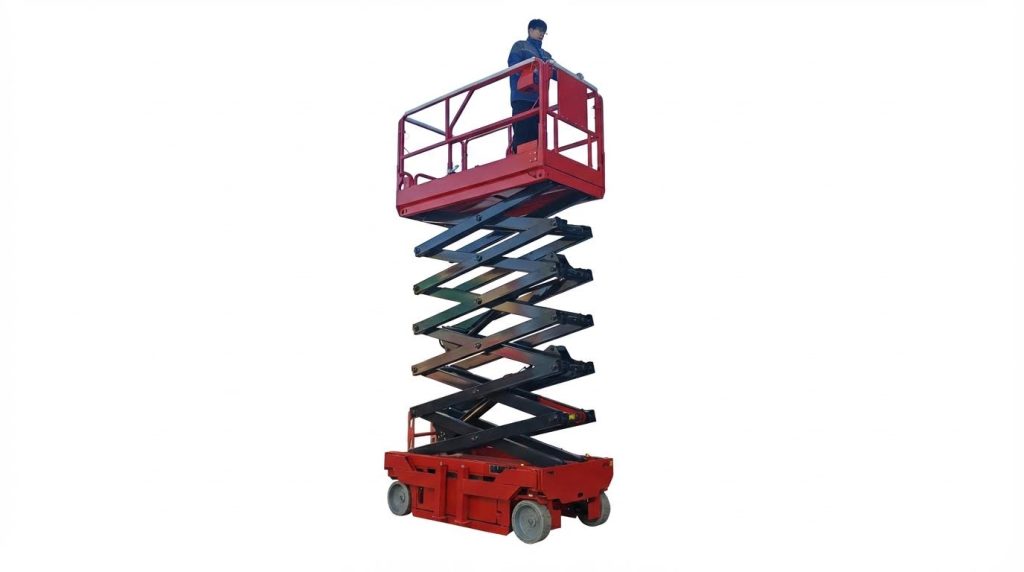
Aerial work platforms that refuse to raise the boom or scissor stack usually have faults in electrical supply, hydraulic generation, or structural and load‑sensing systems. This article explains a safe, systematic approach to lockout/tagout, initial diagnostics, and functional mapping so you can answer “why won’t my aerial work platform lift” with evidence instead of guesswork.
You will see how to trace power from batteries or engines through controls and interlocks, then verify hydraulic pressure, cylinders, and mechanical load paths. The final section summarizes best practices for safe, repeatable troubleshooting that aligns with regulatory expectations and modern maintenance standards.
Initial Safety, LOTO, And Diagnostic Strategy
Technicians asking “why won’t my aerial work platform lift” must start with safety and structure. A disciplined lockout/tagout (LOTO) and diagnostic strategy prevents unintended movement and electrical or hydraulic hazards. It also creates a clear path to separate safety interlock issues from hydraulic, electrical, or load-related causes. This section explains how to secure the machine, gather correct technical data, map failed functions, and assess site and loading conditions before deeper troubleshooting.
Lockout/Tagout Steps For Aerial Platforms
Before investigating why an aerial platform will not lift, technicians must place the machine in a fully controlled state. Park the unit in an approved area, on firm, level ground, away from traffic and overhead hazards, then chock wheels where roll-away is possible. Fully lower the boom or scissor stack into the stowed position and engage transport pins, locks, or straps so elevating and rotating assemblies cannot move unexpectedly. Activate emergency stops at both ground and platform controls, turn the key or selector to the off position, and remove the key to prevent re-energizing. Open battery or engine compartments, switch any battery or master disconnects to off, and padlock them if the design allows. Finally, tag both upper and lower controls with weather-resistant LOTO tags that state the fault description, date, and responsible person, and inform supervisors according to site procedures.
Verifying Manuals, Serial Data, And Settings
Once the platform is locked out, the next step is to confirm that technicians use the correct technical baseline for diagnostics. Record the full model and serial number from the identification plate, which typically also lists hydraulic main and lift relief settings, maximum platform height, and drive-height limitations. Use this data to pull the exact operating, service, and parts manuals, whether from a local digital library or an updated portable drive, so wiring diagrams, hydraulic schematics, and parameter tables match the machine. Verify that any user-adjustable settings, such as lift speed limits, drive-at-height interlocks, or configuration options, align with the documentation and job requirements. If the serial plate is damaged or missing, arrange a replacement and avoid guessing pressures or limits, because incorrect assumptions can hide the root cause of a no-lift condition or create unsafe test conditions.
Functional Mapping To Isolate Common Faults
When an operator reports “the lift will not go up,” the underlying problem may affect several functions, not just elevation. Before disassembly, perform a structured functional check after temporarily energizing the machine under controlled conditions, still within site safety rules. Test drive, steer, lift, lower, and any extend or rotate functions, then map which functions work and which do not. Look for patterns: for example, if lift and extend both fail while drive and steer operate normally, the issue may relate to a shared elevation enable circuit, limit switch, or hydraulic valve group. If every function at the platform fails but ground controls still operate, suspect control-station wiring, selector switches, or platform E-stops. This functional mapping narrows the diagnostic scope, reduces unnecessary component replacement, and quickly indicates whether the primary fault is electrical control, hydraulic supply, or a safety interlock.
Environmental And Load Conditions Checklist
Environmental and loading conditions often explain why an scissor platform will not lift or lifts very slowly. Confirm that the platform load, including tools and occupants, does not exceed the rated capacity stated on the data plate; overweight conditions can trigger protective limits or stall hydraulic systems. Inspect ground conditions for slope, soft soil, or unstable surfaces, because tilt sensors or stability logic may inhibit lift when the chassis is out of level. Consider temperature and weather: very low temperatures increase hydraulic fluid viscosity, while hot, humid conditions promote electrical moisture intrusion and overheating, both of which degrade lift performance. Check for strong wind, rain, or nearby obstacles that may cause the control system or operator to restrict motion. Document these environmental and load factors alongside the functional map so later electrical and hydraulic measurements are interpreted in the correct operating context.
Electrical Power, Controls, And Interlocks

When technicians ask “why won’t my aerial work platform lift,” electrical power and interlocks are prime suspects. A structured check of supply, controls, and safety circuits often reveals the root cause. This section explains how to evaluate batteries or engine power, control stations, safety devices, and wiring integrity before moving on to hydraulics.
Battery, Engine Power, And Ground Circuits
If you wonder why won’t my aerial work platform lift, start with its power source. For electric units, measure battery open‑circuit voltage and voltage under load at the lift function. Aged batteries, sulfation, or poor charging histories reduced voltage and caused undervoltage lockouts or slow operation. For engine‑powered platforms, verify fuel quality, fuel filters, and that the engine reached rated speed before demanding lift. Always confirm the dedicated ground circuit: aerial platforms used solid white conductors as returns rather than the chassis. Check the ground circuit breaker, continuity of white ground wires, and use those wires as the reference when placing voltmeter leads. Any high resistance or open in the ground path could prevent valve coils and contactors from energizing, leaving the lift inoperative.
Control Stations, E‑Stops, And Selector Switches
Control architecture often explained why won’t my aerial work platform lift even when power looked normal. Inspect both lower and upper control stations, because a mispositioned selector switch could disable the active station. Verify that emergency stop buttons at every station latched and released correctly; a single engaged E‑stop opened the control circuit and blocked all lift commands. Measure control supply voltage at joysticks or proportional controllers with the selector in each position to confirm transfer. Check that removable upper control boxes seated fully in their receptacles and that any interlock pins engaged. Faulty or contaminated key switches, selector switches, or potentiometers could intermittently break the control chain, so technicians tested continuity across each switch in its commanded position.
Limit Switches, Sensors, And Software Faults
Interlock devices frequently answered the question why won’t my aerial work platform lift when other functions still worked. Height, tilt, and overload sensors fed signals to the control module that could inhibit elevation. If the platform sat on a steep or uneven surface, a tilt sensor might legitimately block lift; relocating the machine to level ground was a quick diagnostic step. Technicians compared which functions failed together to map shared limit switches or valves and isolate the suspect device. On modern units, the control system logged fault codes for sensor out‑of‑range conditions or internal software errors. Reading diagnostic codes and live sensor values with the correct service manual allowed accurate identification of failed sensors versus wiring or controller issues, avoiding unnecessary parts replacement.
Wiring, Connectors, And Moisture Intrusion
Corrosion and moisture in harnesses often turned into the hidden answer to why won’t my aerial work platform lift. High humidity, rain, and wash‑downs promoted oxidation on connector pins and wicking of moisture under insulation. Inspect all harness runs to the lift valve manifold, limit switches, and control boxes for abrasion, crushed sections, or previous repairs. Open connectors and look for green corrosion products, bent pins, or looseness that could create intermittent opens under vibration. Technicians dried wet enclosures, applied appropriate contact cleaners, and replaced compromised connectors rather than relying only on sealants. They verified continuity and insulation resistance from the controller to each coil using the white ground return as reference. Restoring clean, low‑resistance circuits usually recovered reliable lift function without hydraulic intervention.
Hydraulic Supply, Actuation, And Mechanical Load
When technicians ask “why won’t my aerial work platform lift,” hydraulic issues often sit near the top of the fault list. The lift circuit depends on correct fluid condition, verified pressure, free cylinder motion, and a structure that carries load without binding. A systematic check of hydraulic supply, actuation, and mechanical load paths helps separate true hydraulic faults from electrical or control problems. The following subsections focus on practical field diagnostics that align with manufacturer guidance and inspection standards.
Hydraulic Fluid Level, Quality, And Temperature
Low or aerated hydraulic fluid frequently caused aerial work platforms to stall or lift very slowly. Start with the machine on level ground and confirm fluid level against the sight gauge or dipstick specified in the service manual. Fluid that appeared milky, dark, or with visible particles indicated water ingress, oxidation, or internal wear debris, all of which reduced pump efficiency and could damage valves and cylinders. Temperature mattered as well: cold fluid in winter or uncooled fluid in hot summer conditions increased viscosity, raised pressure losses, and delayed lift response. If an operator asked “why won’t my aerial work platform lift” during hot weather, technicians checked for degraded fluid, clogged coolers, and overheating that thinned the oil and reduced available pressure under load.
Pumps, Relief Valves, And Pressure Verification
If fluid condition looked acceptable, the next step involved confirming that the pump actually produced the pressure required on the serial plate. Technicians installed calibrated pressure gauges at the test ports specified by the manufacturer and compared readings against main and lift relief valve settings. A low reading across all functions pointed toward a worn pump, suction restriction, or slipping pump coupling, while normal drive or steer pressures with low lift pressure indicated a lift-specific relief or valve issue. Contaminated fluid sometimes caused relief valves to stick partially open, bleeding off pressure so the platform would not rise or would only creep. Documented pressure tests answered the core field complaint “why won’t my aerial work platform lift” with data, not guesswork, and supported safe adjustment of relief valves back to factory values.
Cylinders, Hoses, Leaks, And Mechanical Binding
Even with correct system pressure, internal or external leakage in the lift circuit could prevent elevation. Inspectors checked hoses, fittings, and manifolds for wet spots, atomized spray, or dirt accumulation that indicated leaks, especially around cylinder ports and swivel joints. Aerial work platforms also suffered from internal cylinder bypass, where worn seals allowed fluid to leak past the piston; the gauge showed pressure, but the boom or scissor stack failed to rise or drifted down under load. Technicians performed controlled lift tests and monitored for movement lag, drift, or uneven extension that suggested bypass or mechanical binding. Corrosion, bent scissor arms, misaligned pins, or dry pivot points increased friction enough that operators reported “why won’t my aerial work platform lift” even though hydraulic components seemed healthy at first glance.
Load, Stability Devices, And Structural Checks
When an aerial work platform refused to lift despite adequate hydraulic pressure, load and stability protections often explained the behavior. Technicians verified that the platform load stayed within the rated capacity on the data plate, including tools and materials, because overload conditions triggered interlocks or caused the lift to stall hydraulically. Outriggers, stabilizers, or axle extensions that failed to deploy or to confirm ground contact could inhibit boom elevation through sensors or software, especially on rough-terrain units. Structural inspections of welds, booms, scissor stacks, and chassis attachment points identified cracks, deformation, or twisted members that created binding or unsafe geometry under load. By combining structural checks with confirmation of load and stability device status, technicians answered “why won’t my aerial work platform lift” in a way that protected both the machine and personnel, not just restored motion.
Summary: Safe, Systematic AWP Lift Troubleshooting
Technicians asking “why won’t my aerial work platform lift” needed a structured, safety‑first process. A lockout/tagout routine isolated energy sources and prevented inadvertent motion during diagnosis. Systematic testing of all functions, rather than only the failed lift, revealed shared dependencies such as limit switches, valves, or interlocks. Using model‑ and serial‑specific manuals ensured correct pressure settings, wiring conventions, and control logic during every step.
From an electrical standpoint, reliable battery or engine power, solid ground circuits, and dry, intact connectors were essential for any lift command to execute. White ground conductors and dedicated ground breakers provided known reference points for voltage checks instead of using the chassis. Control stations, emergency stops, and selector switches had to be in the proper states, with sensors and software free of stored faults that could inhibit elevation. Moisture intrusion, corrosion, or loose terminals often explained intermittent “no lift” complaints, especially in hot, humid, or rainy conditions.
Hydraulic analysis answered another version of “why won’t my aerial work platform lift” when electrical checks passed. Adequate fluid level, correct viscosity for ambient temperature, and clean hydraulic oil supported stable pressure. Technicians verified pump output and relief valve settings against data plates and manuals, then inspected cylinders, hoses, and structural members for leaks, binding, or deformation. Load and stability devices, including outriggers and limit switches, had to confirm safe conditions before the control system allowed lift motion.
Going forward, the industry continued to move toward more sensors, software interlocks, and data‑driven maintenance. This evolution improved safety but required stronger diagnostic discipline, better documentation, and routine inspections of electrical, hydraulic, and structural systems. A balanced approach combined annual inspections, condition‑based maintenance, and thorough fault‑tree style troubleshooting. When technicians followed this safe, systematic workflow, they minimized downtime, answered “why won’t my aerial platform lift” with evidence, and restored reliable operation while maintaining regulatory compliance.
