Hydraulic scissor lifts relied on tightly integrated structures and fluid power systems to raise platforms safely and efficiently. This article examined the core scissor geometry and load paths, then linked these mechanics to hydraulic circuit design and control strategies. It also detailed common failure modes, maintenance practices, and diagnostics for hydraulic, structural, and electrical subsystems. Finally, it summarized best-practice guidelines and emerging design trends that improved reliability, safety, and lifecycle performance of industrial scissor lifts.
Core Scissor Lift Geometry And Load Path
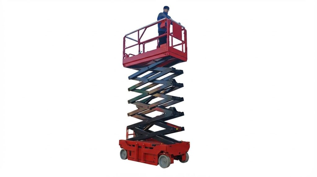
Core geometry defined the efficiency, capacity, and safety margin of hydraulic scissor lifts. Engineers relied on a clear understanding of load paths through the arms, pivots, and platform to avoid overload and instability. Geometry also governed cylinder force requirements and influenced hydraulic circuit sizing. Robust design balanced compact stowed height, required stroke, and structural stiffness.
Scissor Arm Kinematics And Mechanical Advantage
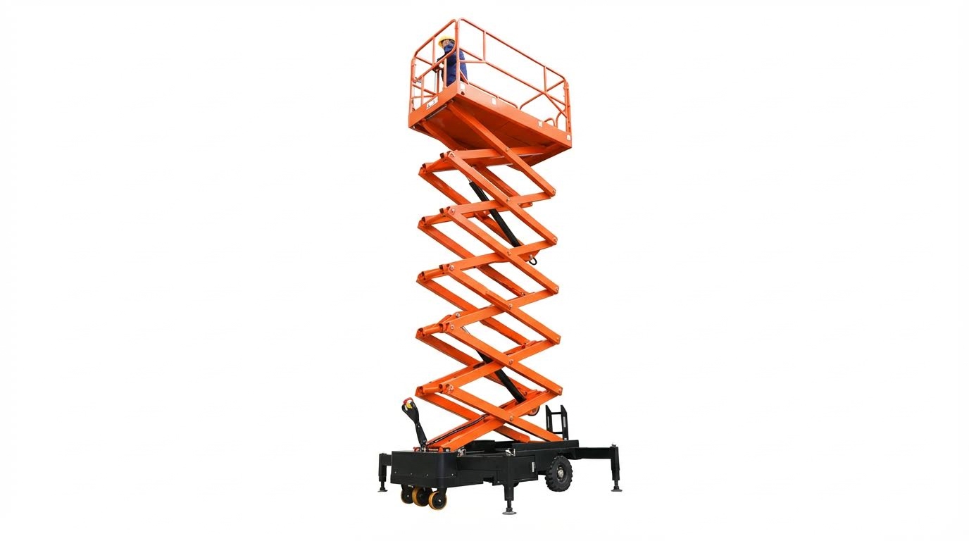
Scissor arm kinematics converted linear cylinder stroke into vertical platform motion. At low platform heights, the arm angle to the base stayed shallow, so the mechanical advantage remained high. The cylinder needed relatively low pressure but delivered limited vertical displacement per millimetre of stroke. As the platform rose and arm angle increased, mechanical advantage decreased, requiring higher cylinder force for the same load. Designers therefore sized cylinders and hydraulic pressure limits for the worst-case low-angle condition, where internal forces in pins and arms peaked. Kinematic analysis also set constraints on maximum platform height, folded length, and interference between crossing arms and hoses.
Platform, Base, And Pivot Point Design
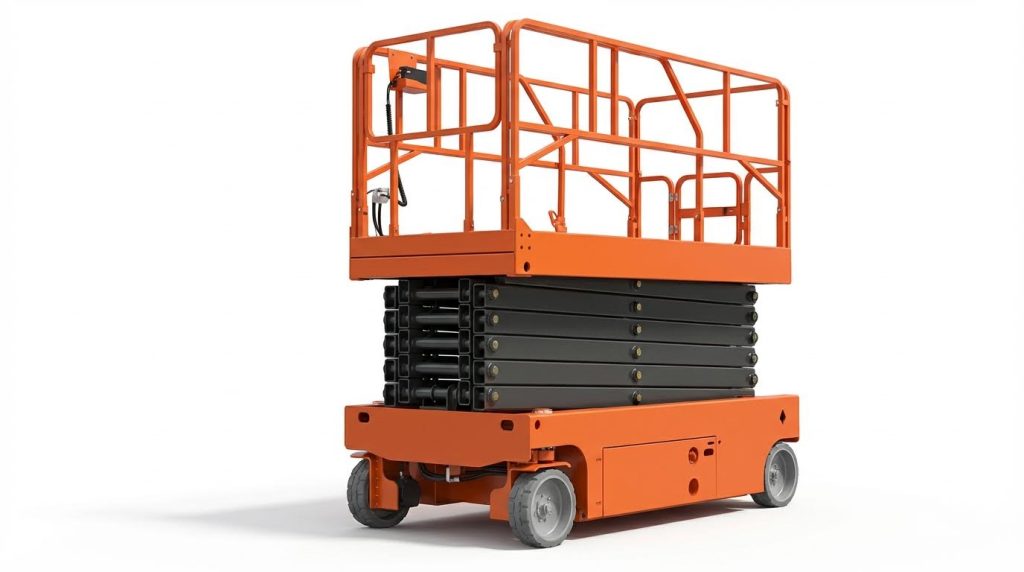
The platform distributed applied loads from personnel, tools, and materials into the scissor arms. Engineers specified deck plate thickness, stiffeners, and guardrail attachment points to control local deflection and meet safety codes. The base frame anchored the scissor assembly to the chassis or pit and transferred loads into the ground with adequate bearing area. Pivot point locations along the arms determined lift stroke, lateral stability, and required cylinder force. Bushings, pins, and brackets at these pivots carried cyclic shear and bending, so designers selected diameters and materials for defined duty cycles and inspected them for wear during maintenance. Proper pivot alignment limited binding and reduced hydraulic pressure spikes during motion.
Structural Stiffness, Deflection, And Stability
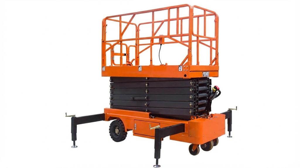
Structural stiffness governed perceived platform solidity and influenced operator confidence. Engineers controlled deflection of arms and platform using closed-section beams, appropriate arm depth, and bracing where needed. Vertical deflection under rated load stayed within limits defined by standards for industrial lifts. Lateral and torsional stiffness also mattered, especially for tall, narrow lifts exposed to side loads or wind in outdoor use. Stability analysis considered the combined centre of gravity of lift and load relative to the base support polygon. Designers evaluated overturning moments from eccentric loads and horizontal forces and compared them with restoring moments. They integrated stabilizers or outriggers where necessary and defined operational envelopes that operators followed during pre-use checks.
Load Ratings, Duty Cycles, And Fatigue Life
Load ratings represented the maximum permissible platform load, including personnel and equipment, under specified conditions. Engineers derived these ratings from static and dynamic load cases with defined safety factors against yield and buckling. Duty cycles described expected numbers of lift-lower operations and the proportion of time under load, guiding fatigue design. Scissor arms, pivots, and welds experienced high-cycle loading, so designers used fatigue-resistant details and verified stress ranges against S–N data. Hydraulic components and pins were sized for both peak load and cumulative cycles. Documented duty classes and maintenance intervals aligned with actual usage patterns to preserve fatigue life and keep structural safety margins intact over the lift’s service life.
Hydraulic Circuits And Lifting Operation

Hydraulic circuits in scissor lifts converted electrical or engine power into controlled linear motion at the lift cylinders. Designers balanced flow, pressure, and component sizing to achieve required platform speed, capacity, and positional accuracy. Safe operation depended on predictable behavior during lifting, holding, and lowering, even under varying loads and temperatures. Understanding circuit functions allowed engineers and technicians to diagnose faults quickly and implement robust control strategies.
Pump, Motor, And Cylinder Sizing Fundamentals
Engineers sized the hydraulic pump and electric motor to deliver the required flow at the maximum working pressure with adequate margin. Pump displacement and motor power determined platform raise speed, considering cylinder bore, stroke, and the scissor mechanism’s motion ratio. Cylinder bore area set the theoretical lifting force as product of pressure and effective area, while rod diameter influenced retraction force and buckling resistance. Designers checked duty cycles to avoid motor overheating and ensured reservoir volume limited oil temperature rise during repeated lifts.
Scissor geometry amplified cylinder stroke into larger platform travel, so small changes in cylinder size significantly affected performance. Engineers verified that maximum pressure under rated load stayed below relief valve settings and component pressure ratings. They also considered starting torque requirements for the motor, especially in cold conditions with high oil viscosity. This sizing process balanced energy efficiency, response time, and long-term reliability.
Relief, Check, And Lowering Valve Functions
Relief valves protected the hydraulic circuit by limiting maximum pressure, typically around 16 MPa in industrial scissor lifts. If load or blockage caused pressure to exceed the set point, the relief valve opened and diverted flow back to tank, preventing hose or cylinder rupture. Incorrect relief adjustment or contamination could cause slow lifting, inability to reach full height, or overheating from continuous bypass flow. Maintenance procedures required cleaning and readjusting relief valves when pressure readings deviated from specifications.
Check valves maintained load holding by preventing reverse flow when the pump stopped or when directional valves centered. Electromagnetic check or holding valves in aerial platforms locked cylinders to minimize drift-down, and faults in these valves led to unintended descent. Lowering valves controlled discharge from the cylinder side supporting the load, governing down speed and ensuring smooth motion. Open or leaking manual lowering valves, or stuck spools, caused slow lift, no-lift, or uncontrolled lowering, so technicians inspected these valves early in troubleshooting.
Oil Selection, Temperature Control, And Filtration
Hydraulic oil selection affected efficiency, wear, and low-temperature performance of scissor lifts. Manufacturers specified ISO VG grades such as HL-N46 or Super Highland 32, matching viscosity to expected ambient temperature between 0 °C and 40 °C. Excessively viscous oil increased pressure losses and start-up loads, while low viscosity reduced lubrication film thickness and accelerated pump and valve wear. Operators followed recommendations to change oil after 200 hours of initial operation and then roughly every six months under normal conditions.
Filtration strategies kept particle contamination below target cleanliness levels, using return-line filters, strainers, and periodic tank cleaning. Clogged strainers or filters restricted flow and caused slow lifting or cavitation, so maintenance schedules included regular inspection and replacement. Thermal control relied on correct reservoir sizing, ambient cooling, and avoiding prolonged stall conditions that heated oil rapidly. Abnormal temperature rise or noisy operation signaled issues such as internal leakage, relief valve bypassing, or pump degradation, requiring immediate inspection before further use.
Proportional Control, Drift, And Speed Regulation
Scissor lift designers used flow control and proportional valves to regulate platform speed and achieve smooth motion. Spill or metering valves allowed technicians to adjust scissor movement speed by turning plugs clockwise
Failure Modes, Maintenance, And Diagnostics
Hydraulic Leaks, Seal Wear, And Hose Degradation
Hydraulic scissor lifts operated on sealed circuits, so any leakage directly reduced lifting efficiency and safety margins. Typical leak locations included cylinder rod seals, manifold O-rings, quick-connects, and flexible hose crimps. Progressive seal wear caused internal bypass, which reduced effective cylinder force without obvious external oil loss. External leaks reduced system pressure, contaminated work areas, and increased slip hazards around the base frame.
Degradation mechanisms included thermal ageing of elastomers, chemical incompatibility with non-approved oils, and abrasion from contaminated fluid. Hose covers cracked under ultraviolet exposure and bending fatigue, while reinforcement layers corroded or broke under cyclic pressure. Technicians inspected for wet fittings, oil mist, cracked hose jackets, and softened rubber at clamp points. Corrective actions involved replacing damaged hoses and seals, restoring fluid to manufacturer-specified levels, and bleeding air before functional testing.
Unaddressed leaks led to reduced rated capacity, erratic platform motion, and higher risk of sudden creep or drop. Industry practice required leak checks during every pre-use inspection and detailed hose condition audits at defined hour intervals. Using manufacturer-approved seal materials and hose constructions helped maintain compatibility with specified hydraulic oils and temperature ranges. Documented leak repairs supported compliance with safety standards and internal maintenance procedures.
Slow Lift, No-Lift, And Drift-Down Troubleshooting
Slow or no-lift conditions indicated insufficient hydraulic pressure at the lift cylinder or mechanical interference in the scissor stack. When the motor ran but the platform did not rise, root causes included reverse phase rotation on three-phase units, damaged pumps, stuck or energized-open check valves, and misadjusted relief valves venting pressure. Contaminated strainers, partially closed manual lowering valves, and low oil levels also reduced volumetric flow and extended lift times. Technicians verified oil level, pump rotation, and system pressure at test ports before disassembling components.
No-lift with a stationary motor suggested electrical issues such as tripped breakers, insufficient supply voltage, failed contactors, or open control switches. Diagnostic steps followed a structured sequence: confirm power, verify control circuit continuity, check coil voltages on solenoid valves, then evaluate mechanical binding in the scissor arms or platform guides. Excess platform mass above rated load also prevented lift and required immediate unloading and capacity verification. Restoring correct relief valve settings to manufacturer values, typically in the tens of megapascals, ensured the circuit delivered design force while protecting structure and hoses.
Drift-down during a static hold test pointed to internal leakage rather than external structural deformation. Common sources included worn cylinder piston seals, contaminated or damaged holding valves, and leaking lowering valves or manual overrides left cracked open. Technicians measured drift rate under a fixed load and compared it with allowable limits in the service manual. Corrective measures involved cleaning or replacing valves, resealing cylinders, and flushing contaminated circuits to remove particles that prevented full valve closure.
Thermal Protection, Motor Faults, And Power Issues
Hydraulic power units on scissor lifts relied on electric motors protected by thermal devices to prevent winding damage. Frequent cycling, high ambient temperatures, or extended operation near maximum load increased motor current and temperature. Thermal protectors opened the circuit when the motor overheated, resulting in a non-running motor despite available line voltage. After cooling, automatic-reset protectors reclosed, but repeated trips indicated underlying overload or supply issues that required correction rather than bypassing the device.
Motor non-start conditions arose from single-phasing, low supply voltage, failed contactors, or open overload relays. Field diagnostics included checking line-to-line voltages, inspecting contactor contacts, and verifying control voltage at the coil terminals when the up command was active. Insulation resistance tests identified winding degradation before catastrophic failure. For motors that ran but delivered low torque, technicians evaluated supply sag under load, mechanical drag in the pump, and internal pump wear that reduced volumetric efficiency.
Power quality and wiring integrity strongly influenced hydraulic performance and reliability. Undersized cables created voltage drops, especially on long runs to mobile lifts, which reduced motor torque and
Summary Of Best Practices And Design Trends
Hydraulic scissor lift design and operation relied on a tight integration of structure, hydraulics, and controls. Effective practice combined robust scissor geometry, correctly sized hydraulic components, and disciplined maintenance to preserve lifting capacity and safety margins over the service life. Field data showed that hydraulic integrity, particularly leak prevention and control valve performance, directly affected platform behavior, including lift speed, drift-down, and stability. As fleets aged, structured inspection programs became the primary tool for containing unplanned downtime and incident risk.
Best practice in operation and maintenance emphasized sealed, leak-free hydraulic circuits, regular fluid changes, and strict adherence to manufacturer fluid specifications. Technicians inspected hoses, cylinders, and fittings for seepage or abrasion, verified relief valve settings, and confirmed correct operation of holding and lowering valves before returning equipment to service. Daily pre-use checks covered oil level, abnormal noise, rapid oil temperature rise, and erratic platform motion, with immediate lockout for any anomalies. Training and certification for operators, supported by periodic recertification, reduced misuse-related failures, such as overloading, improper stabilizer deployment, or defeating safety devices.
Design trends moved toward higher diagnostic transparency, tighter control of motion, and improved lifecycle reliability. Manufacturers incorporated more sensors for pressure, temperature, and position, enabling clearer fault codes and faster root-cause analysis of issues like slow lift, no-lift, or unintended drift. Controls evolved from simple on/off valves to proportional or electronically modulated systems, improving speed regulation and reducing shock loads on scissor arms and pivots. At the same time, designers maintained conservative structural factors of safety, refined weld details, and standardized inspection points to simplify structural integrity checks.
From an implementation perspective, asset owners benefited most when they paired modern designs with disciplined maintenance regimes. This included codified inspection intervals for cylinders, hoses, and valves; documented fluid and grease specifications; and clear criteria for component replacement rather than repair-in-place. Aligning maintenance data with observed failure modes allowed optimization of service intervals, reducing both premature overhauls and late interventions. Looking forward, integration with digital maintenance systems, predictive analytics on hydraulic condition, and further refinement of energy-efficient power units were expected to reduce operating costs while maintaining or improving safety performance.
