Safe scissor lift transport depended on rigorous engineering checks, controlled loading, and compliant on-road practices. This article followed the complete workflow defined in the outline, from pre-transport engineering checks through loading, restraint design, and unloading. It integrated OEM data, stability calculations, and field procedures aligned with regulatory requirements and practical site constraints. The goal was to give engineers and fleet managers a structured, calculation-aware approach that reduced tipping risk, equipment damage, and regulatory non-compliance across the entire transport cycle.
Pre-Transport Engineering Checks And Preparation
Interpreting OEM Limits, Weight, And CG Data
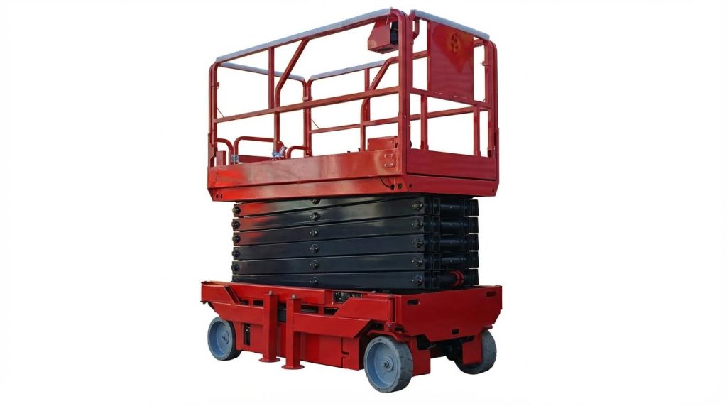
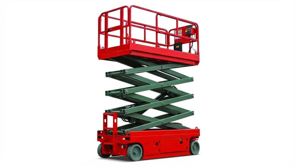
Engineers should start with the manufacturer’s manual and nameplate data. These documents state rated load, gross machine mass, maximum platform height, and approved tie-down points. Compare scissor lift mass and dimensions with the transport vehicle’s payload rating and deck size to avoid overloading. Confirm axle loads and deck load distribution so the lift’s center of gravity remains between the trailer axles. Use OEM center-of-gravity (CG) diagrams where available; if not, assume a CG near the chassis centerline, biased toward the drive axle. Always transport with the platform fully retracted to lower the CG and reduce rollover risk.
Structural And Hydraulic Pre-Transport Inspection
Before loading, carry out a focused structural and hydraulic inspection. Check the scissor arms, pivot pins, welds, and base frame for cracks, corrosion, deformation, or loose fasteners. Inspect the platform guardrails, toe boards, and gate latches to ensure they lock correctly and will not rattle free in transit. Examine hydraulic cylinders, hoses, and fittings for leaks, abrasion, or bulging, and verify that the lift raises and lowers smoothly during a brief functional test. Confirm tire or wheel condition, pressure, and wheel nut torque, since damaged or underinflated tires can destabilize the lift on ramps. Document defects and correct any safety-critical issues before authorizing transport.
Lockout, Battery Isolation, And Platform Securing
Once the lift passes inspection, place it in a transport-safe state. Fully retract the platform and engage any mechanical or hydraulic locking devices designed to prevent unintended elevation. Turn off the main power; for electric units, isolate the battery according to OEM instructions, typically by disconnecting the main battery plug or negative terminal. Secure disconnected leads so they cannot contact each other or grounded metal during vibration. Remove or tie down loose items on the platform, including tools, materials, and removable control boxes. Where available, apply lockout or tagout devices to the primary disconnect or key switch to prevent unauthorized operation during loading, transport, and unloading.
Regulatory, Permit, And Route Clearance Review
Before dispatch, verify regulatory compliance for the planned route. Compare combined vehicle and load dimensions with legal limits for height, width, length, and mass in each jurisdiction. If the loaded scissor lift exceeds standard limits, obtain oversize or overweight permits and determine any escort vehicle requirements. Measure the transport height from road surface to the highest point of the stowed lift to confirm clearance under bridges, overpasses, power lines, and tree branches. Check local rules on load securement, tie-down capacity, and the use of warning flags, lights, and signage for projecting or wide loads. Finally, select a route that minimizes sharp curves, steep grades, and poor road surfaces to reduce dynamic loads on the lift and its restraints.
Loading Methods, Stability Control, And Tie-Down Design
Ramp, Forklift, Crane, And Trailer Selection
Engineers selected the loading method by matching equipment ratings to the scissor lift’s gross mass and geometry. Flatbed trucks or trailers with integrated or portable ramps provided the primary transport platform, provided their payload rating exceeded the lift weight with at least 20% margin. Where the vehicle lacked a built-in ramp, operators used portable ramps specifically rated above the combined wheel load of the lift, ensuring secure anchorage to the deck. Forklifts or cranes only handled lifts when their rated capacities at the working load radius exceeded the lift weight and when approved lifting points were available.
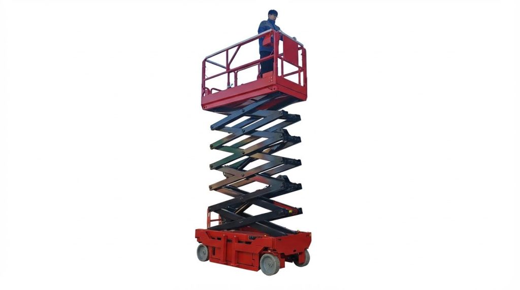
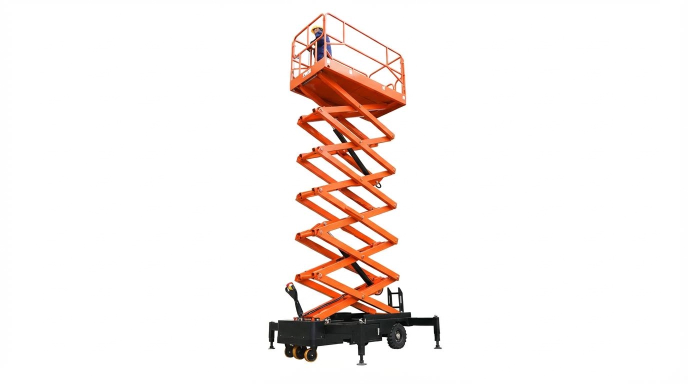
Self-propelled lifts typically drove onto the trailer at low speed, while non–self-propelled units required a winch or mechanical assistance. Purpose-built galvanized trailers with low decks improved stability by lowering the transport center of gravity and reducing ramp angles. Engineers oriented the lift so the platform structure faced forward and the wheelbase aligned centrally over the trailer axles to balance axle loads. For oversized or heavy-duty units, operators evaluated whether specialized low loaders or professional heavy-haul services were more appropriate.
Ramp Geometry, Friction, And Tipping Risk Control
Ramp design and positioning strongly influenced tipping risk during loading. Operators kept ramp angles low, typically below 15°, to limit the shift in center of gravity as the lift climbed. They verified that the ramp surface provided adequate friction, using textured steel, anti-slip coatings, or timber cleats to maintain tire grip under wet or dusty conditions. The ramp interface with the trailer deck required positive locking or pinning to prevent relative movement or kick-out during loading.
During ascent, operators maintained slow, steady motion to avoid dynamic pitching that could destabilize the lift. They aligned the lift square to the ramp to prevent lateral load transfer and side slip. Chocks or blocking at the ramp sides and trailer wheels reduced the risk of trailer movement or off-edge excursions. Before each operation, engineers checked ramp load ratings, weld integrity, and fasteners to ensure the structure withstood repeated wheel loads without yielding.
Winch-Assisted Loading For Heavy Units
For larger or heavier scissor lifts, winch-assisted loading improved control and reduced reliance on traction. Operators selected winches with line pull ratings exceeding the maximum required drawbar force, including an allowance for ramp slope and rolling resistance. They attached the winch cable only to manufacturer-approved towing or lifting points, avoiding guardrails, platform rails, or hydraulic components. A snatch block or pulley sometimes redirected the line to maintain straight alignment with the ramp centerline.
Winch operation proceeded at low speed, with continuous communication between the winch operator and spotters near the lift. Personnel stayed clear of the cable line of fire to mitigate risks from potential cable failure. Operators kept the lift’s drive controls in neutral and used service brakes only for fine control near the trailer crest. Once the lift reached its final deck position, they applied parking brakes or wheel chocks before disconnecting the winch.
Tie-Down Point Selection And Lashing Configuration
Tie-down design focused on keeping the scissor lift’s base rigidly coupled to the trailer under braking, cornering, and vertical road inputs. Engineers used high-strength ratchet straps or chains attached to designated tie-down points on the lift’s base frame and to certified anchor points on the trailer. They avoided connecting to platform rails, scissor arms, or removable covers, which could deform under preload. Typical configurations used at least four tie-downs, arranged symmetrically in an X-pattern fore and aft to resist longitudinal and lateral forces.
Operators tensioned lashings to remove slack without overloading structural members or suspension components. After securing, they manually pushed or rocked the lift to confirm minimal relative movement, then re-tensioned as necessary. Wheel chocks or blocks added a secondary restraint against rolling, especially on slightly sloped decks. For long-distance transport, engineers specified periodic checks of lashing tension because vibration and material creep could reduce preload over time.
On-Road Transport, Monitoring, And Unloading
Vehicle Dynamics, Speed, And Braking Management
On-road behavior of a transport vehicle carrying a scissor lift depended strongly on center of gravity height and load distribution. Operators kept the platform fully retracted and locked to minimize the center of gravity and reduce rollover risk. They verified axle loads remained within rated limits to maintain predictable braking and steering response. During travel, drivers maintained moderate speeds, especially on curves, ramps, and uneven pavements, to limit lateral acceleration.
Hard braking, sharp lane changes, and sudden steering inputs increased the risk of strap loosening or load shift. Drivers used longer following distances to allow progressive brake application and avoid thermal overload of the braking system. On rough surfaces, they reduced speed to limit vertical accelerations that could unload axles momentarily and reduce tire–road friction. Compliance with local speed limits for heavy or oversize loads remained mandatory and often stricter than general traffic limits.
Height and width clearances were critical when planning routes. Operators measured the combined vehicle and lift height and compared it with bridge and tunnel limits. They also considered crosswinds on exposed roads, because taller loads experienced higher overturning moments. Warning flags, lights, or wide-load signs improved visibility for surrounding traffic and reduced cut-in risks during turning.
Periodic Inspection Of Restraints In Transit
Restraint systems experienced relaxation, vibration, and settlement during the first phase of transport. Operators therefore scheduled early and regular stops to inspect chains, ratchet straps, and binders. They checked for slack, damaged webbing, bent hooks, and deformation at tie-down points on both the trailer and the scissor lift. Any strap contacting sharp edges required corner protectors or repositioning to prevent cutting.
During inspections, personnel verified that the lift base remained firmly seated on the deck or chocks. They attempted to rock the lift by hand to confirm that no relative motion occurred between lift and trailer. If movement appeared, they increased the number of tie-downs or improved the lashing geometry, typically using crossed patterns to resist lateral and longitudinal shifts. Strap tails were secured to avoid whipping, which could damage restraints or distract other drivers.
For long-distance transport, checks aligned with fuel or rest stops to minimize additional downtime. Operators documented each inspection, including retensioning actions, to support compliance with local heavy-transport regulations. They also visually confirmed that the platform stayed fully retracted, locking pins remained engaged, and battery isolation remained in place for electric units. Any detected hydraulic leaks or tire damage triggered immediate corrective action before resuming the trip.
Controlled Release Of Restraints And Safe Unloading
Safe unloading started with parking the transport vehicle on a flat, stable, and unobstructed surface near the intended deployment area. The driver applied parking brakes and, where appropriate, wheel chocks to prevent trailer movement. Before releasing restraints, operators verified that ramps or lift gates were correctly positioned and rated for the scissor lift mass. They planned the unloading path to avoid overhead obstructions and pedestrian traffic.
Restraints were released in a controlled sequence to manage stored tension. Personnel stayed out of the potential movement path of chains and straps, loosening each ratchet gradually and keeping body parts clear of pinch points. After removing all tie-downs, they rechecked that the platform remained locked down and that no loose items were present on the deck or the lift. Only then did they initiate movement down the ramp or off the trailer.
Self-propelled lifts descended ramps at very low speed, with smooth control inputs to avoid abrupt acceleration. For non-self-propelled units or steep ramps, a winch or additional personnel provided controlled guidance. Operators maintained three-point contact when walking near the equipment and used appropriate personal protective equipment, such as safety footwear and gloves. After unloading, they conducted a brief post-transport inspection, confirming structural integrity, hydraulic tightness, and correct operation before returning the lift to service.
Summary Of Best Practices And Future Trends
Safe scissor lift transport relied on disciplined engineering checks, controlled loading, and conservative driving practices. Best practice started with strict adherence to OEM data on mass, centre of gravity, approved tie-down points, and transport position. Operators retracted and locked platforms fully, isolated power supplies, and verified structural, hydraulic, and tyre condition before loading. Transport vehicles, ramps, forklifts, or cranes needed rated capacities exceeding the lift’s gross mass, with ramp geometry and friction managed to avoid loss of traction or tipping. During loading, self-propelled lifts moved slowly on secure ramps, heavier units used winches, and all configurations used symmetric, redundant tie-downs anchored to structural points on both lift and trailer. On-road safety depended on moderate speed, extended braking distances, and regular inspections of chains and straps, especially on long trips or rough routes. Stable, level ground and controlled release of restraint tension were essential during unloading to prevent unintended motion.
Future practice in this area trended toward deeper integration of telematics, automation, and advanced materials. OEMs increasingly embedded sensors to monitor strap tension, shock events, and tilt during transit, with data logged for fleet safety analytics. Digital twins and route-planning software were expected to check bridge clearances, gradient limits, and dynamic load effects in advance, reducing over-height and overweight incidents. Lightweight high-strength steels and aluminium alloys in trailers, combined with optimized lashing hardware, improved payload efficiency without sacrificing safety factors. Regulatory frameworks moved toward harmonised requirements for heavy equipment transport, including clearer prescriptions for minimum tie-down counts, working load limits, and documentation of pre-transport inspections. In practice, operators who combined OEM guidance, data-driven planning, and conservative engineering margins would continue to achieve low incident rates while handling larger and more specialised scissor lift fleets.

