Industrial plants relied on 55-gallon drums to store and move liquids, powders, and hazardous chemicals. Safe lifting systems minimized musculoskeletal injuries, crush hazards, and loss of containment during handling. This article reviewed design criteria, regulatory requirements, and PPE selection, then compared manual and mechanical handling strategies. It also examined available lifting devices, advanced automation and simulation methods, and concluded with engineering best practices for lifecycle-safe drum handling.
Key Design And Safety Criteria For Drum Lifting
Engineering safe drum lifting systems required a structured approach to mass, regulations, hazards, and task design. Designers evaluated drum weights, contents, and handling frequency before specifying equipment. Standards such as OSHA and ASME defined minimum safety thresholds but did not replace engineering judgment. A robust system integrated compliant hardware, trained operators, and documented procedures across the drum lifecycle.
Drum Mass, Center Of Gravity, And Load Rating
A typical 55-gallon drum weighed between 180 kg and 360 kg, and sometimes exceeded 900 kg for very dense contents. Engineers had to treat the drum and its contents as a single rigid body with a variable center of gravity (COG). Liquid sloshing, partial fill levels, or internal liners shifted the COG during acceleration, braking, or rotation. Designers therefore selected lifting devices with rated capacities well above the maximum credible drum mass, often using a minimum design factor of 1.5 to 2.0 on static load.
Below-hook lifters, clamps, and fork attachments used working load limits (WLL) based on the weakest load path element. Chain, hooks, and gripping mechanisms all had to meet or exceed the required WLL in the most unfavorable orientation allowed by the manufacturer. Where devices lifted drums horizontally, engineers verified that bending moments on the shell and chime remained within allowable limits to avoid local buckling or crushing. Load tests at 125% of rated capacity, as practiced by several manufacturers under ASME B30.20, provided additional assurance of structural integrity.
Engineers also considered the COG position relative to the lifting points to minimize tilt and dynamic instability. Three-arm grabs and under-drum supports helped center the load and reduce eccentricity. When rotating drums for pouring, designers specified positive locking mechanisms and controlled-rotation gearboxes to manage torque and prevent sudden shifts. These design decisions reduced the risk of dropped drums, uncontrolled swinging, or overload of hoists and supporting structures.
Regulatory Standards And Compliance (OSHA, ASME)
OSHA regulations focused on safe workplace practices rather than prescribing a single method for drum lifting. Requirements under 29 CFR 1910 and 1910.120(j) addressed hazard communication, hazardous waste operations, and general material handling safety. Employers had to ensure that lifting equipment matched the task, operators received training, and procedures limited exposure to hazardous contents. Failure to evaluate the drum’s condition and labeling before movement could violate multiple OSHA provisions.
ASME and ANSI standards provided detailed design and testing criteria for below-the-hook lifting devices. ASME B30.20 governed the construction, inspection, testing, and operation of these devices, while ASME BTH-1 defined design categories and service classes. Many commercial drum lifters were categorized as DESIGN CATEGORY B and SERVICE CLASS 1, meaning non-latching, limited-life service with defined load spectra. Each device required individual proof testing, often at 125% of rated capacity, with documentation in a load test certificate.
Engineers integrated these standards into internal specifications, procurement documents, and inspection checklists. Periodic inspections verified structural condition, deformation, corrosion, and integrity of chains, hooks, and gripping arms. Where forklift attachments were used, compliance extended to powered industrial truck rules, including capacity plate limits and stability requirements. Aligning plant procedures with OSHA and ASME guidance reduced liability and improved consistency across different drum handling devices.
Hazardous Contents, SDS Review, And PPE Selection
Safe drum lifting began with understanding the contents, not just the mass. Labels and Safety Data Sheets (SDS) identified whether materials were flammable, corrosive, toxic, or reactive. If labeling was missing or illegible, best practice treated the drum as hazardous until analysis confirmed otherwise. Engineers and safety professionals used SDS data to define segregation rules, ventilation needs, and emergency response plans for handling incidents.
PPE selection depended on both mechanical risks and chemical hazards. For non-hazardous contents, baseline PPE typically included safety shoes with toe protection, cut-resistant gloves, and eye protection. For corrosive or toxic materials, operators added chemical-resistant gloves, splash goggles, face shields, and sometimes chemical aprons or coveralls. Where over-pressurization was possible, shielding or remote-opening tools reduced the risk of sudden releases when removing bungs or lids.
Designers also considered secondary containment and spill control around lifting and transfer points. Using Mechanical Devices For Vertical Drum Lifting
Mechanical devices for vertical drum lifting reduced manual handling risks in industrial plants. Engineers selected equipment based on drum type, mass, and process requirements. Typical 55-gallon drums weighed between 180 kg and 360 kg, with specialized applications exceeding 900 kg. Proper device selection controlled drum stability, center-of-gravity alignment, and compliance with OSHA and ASME below-the-hook standards.
Forklift Attachments And Clamp-Style Drum Handlers
Forklift-mounted drum handlers allowed operators to lift and transport drums without leaving the cab. Typical devices engaged the drum by its chime, sidewall, or under the lower rim, using mechanical clamps or jaws. Engineers specified capacity at or above the maximum filled drum mass, with factors of safety aligned to ASME B56 and site standards. Clamp-style handlers needed compatibility with steel, plastic, or fiber drums and verification of top-lip geometry. Operators secured drums with positive-lock mechanisms and verified engagement before tilting or traveling. Facilities restricted travel speed, turning radius, and gradient when carrying elevated drums to prevent tip-over. Where hazardous materials were present, engineers integrated secondary containment pallets or overpacks and ensured clear visibility and traffic management.
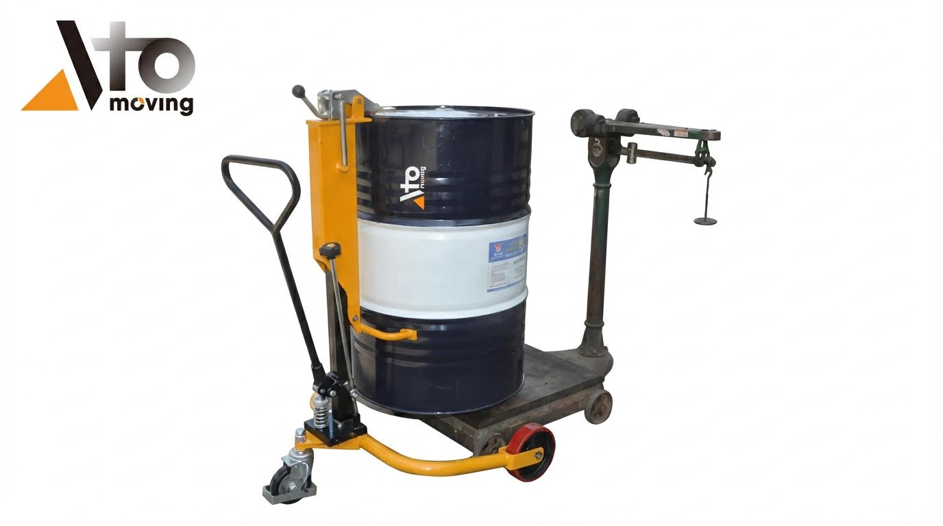
Below-Hook Lifters, Grabs, And Chain Slings
Below-hook drum lifters connected to overhead cranes, hoists, or monorails to lift drums vertically from congested areas or containment sumps. Commercial devices used three-arm grabs, rim clamps, or under-drum support frames rated up to approximately 900 kg to 2,000 lb. ASME B30.20 and BTH-1 governed design category, service class, and proof testing at 125% of rated capacity. Engineers selected lifters based on drum head type, closed or open, and presence of a top lip or chime. Chain sling-based systems used grade 80 or higher chain, with spring-loaded latches for positive engagement on steel, plastic, or fiber drums. Horizontal drum lifters supported drums at both chimes to prevent local shell buckling during lift. Plants implemented inspection programs for hooks, chains, and grab arms, checking deformation, corrosion, and wear before each shift. Tagging systems recorded serial numbers, proof-load certificates, and removal-from-service criteria.
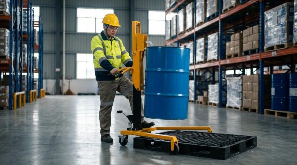
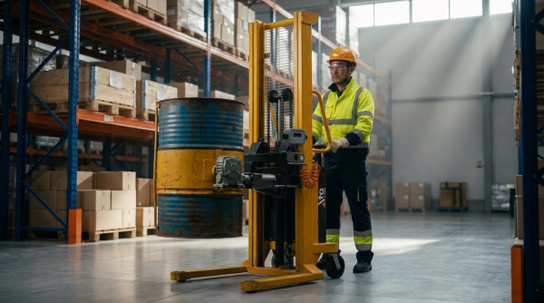
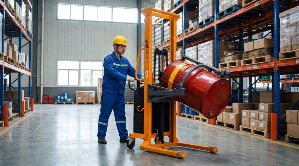
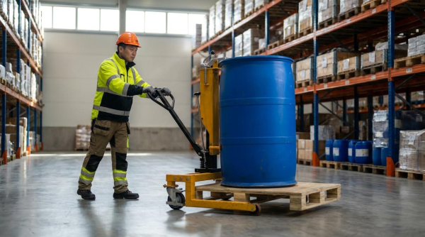
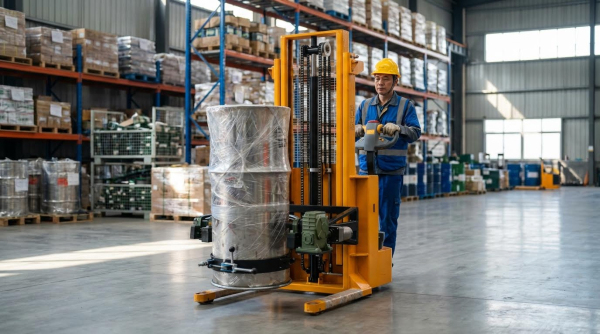
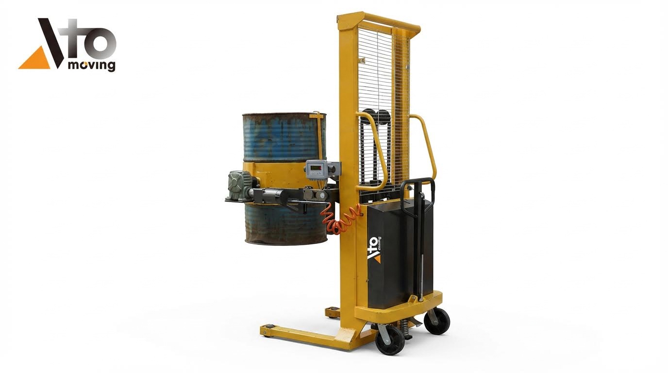
Mobile Drum Stackers, Rotators, And Tippers
Mobile drum stackers combined a wheeled chassis, mast, and gripping head to lift drums from floor level to rack height. Typical designs handled 55-gallon steel or fiber drums with capacities around 250 kg to 700 kg. Manual, hydraulic, or powered drives elevated the drum, while clamps secured the shell or chime. Drum rotators and tippers added controlled 180-degree or 360-degree rotation for pouring into reactors, mixers, or smaller containers. Some units provided hand-crank gearboxes for precise rotation; others used powered rotation for repetitive operations. Engineers verified that rotation axes passed close to the drum center of gravity to minimize torque and unexpected swing. Floor locks or outriggers stabilized the unit during lift and pour, especially at maximum height near 1.6 m to 1.7 m to drum bottom. Selection criteria included aisle width, turning radius, floor flatness, and required discharge height above receiving vessels. For flammable or corrosive contents, designers specified spark-resistant wheels, sealed hydraulics, and compatible seals and coatings.
Drum Storage Racks, Cradles, And Containment
Drum storage systems supported vertically or horizontally stored drums while maintaining access for lifting devices. Vertical racks typically limited stacking to two drums high, consistent with guidance to reduce instability and inspection difficulty. Engineers sized beams and posts for known drum masses and incorporated seismic or impact bracing where required. Horizontal cradles and rack systems stored drums on their sides, supporting both chimes to prevent shell deformation and rolling. Integrated fork pockets or crane lugs allowed safe handling of fully loaded rack modules. Spill containment pallets and bunded racks captured leaks, with sump volumes sized to at least 110% of the largest drum or a regulatory-specified fraction of total volume. Facilities avoided ad hoc stacking on pallets above two high because variable drum geometry and condition reduced stability. Regular inspection routines checked for corrosion, bulging, or damaged chimes, particularly at rack contact points. Designers ensured compatibility between rack spacing and the reach of forklifts, stackers, and below-hook lifters to avoid off-center lifts and side loading of equipment.</
Advanced Methods And Lifecycle Optimization
Advanced drum lifting systems in industrial plants integrated mechanical devices with automation, sensing, and data analytics. Engineers optimized full drum lifecycles, from receipt and storage to dispensing and disposal. This section focused on system-level methods that reduced risk, improved throughput, and lowered total cost of ownership. It also addressed how digital tools and smart maintenance strategies extended the safe service life of lifting attachments.
Integrating Hoists, Cranes, AGVs, And Cobots
Engineers integrated overhead hoists and bridge cranes with drum lifters to handle vertical lifting where forklifts had limited access. Below-hook drum lifters, compliant with ASME B30.20 and BTH-1, allowed controlled raising, lowering, and tilting of 55-gallon drums up to 1,000 kg, depending on model rating. Automated guided vehicles (AGVs) transported drums along fixed routes, while cobots handled localized tasks such as positioning drums under filling heads or into containment pallets. Successful integration required clear traffic segregation, interlocked safety zones, and standardized drum interfaces, such as consistent chime geometry and lifting points. Control systems synchronized hoists, AGVs, and cobots to avoid conflicts, using sensors to detect drum presence, misalignment, or obstruction before motion.
Digital Twins And Simulation Of Drum Workflows
Digital twins of drum handling areas replicated equipment, drum weights, and traffic patterns in a virtual environment. Engineers used simulation to test alternative layouts, crane spans, AGV routes, and storage rack configurations without disrupting production. Models incorporated realistic drum masses between 180 kg and 360 kg for typical filled 55-gallon units, plus higher values for dense liquids or solids. The simulations evaluated collision risk, bottlenecks at loading points, and ergonomic exposure at manual intervention stations. By iterating scenarios, teams selected lifting devices and drum lifter types that met throughput targets while maintaining safe clearances and stable drum trajectories. After deployment, operational data refined the digital twin, improving forecasts for peak periods and maintenance windows.
Predictive Maintenance For Lifting Attachments
Predictive maintenance strategies monitored drum lifters, clamps, and chain slings to prevent in-service failures. Standards such as ASME B30.20 required initial proof load tests at 125% of rated capacity, which manufacturers already performed on compliant below-hook devices. Plants then tracked service hours, lift counts, and overload events using counters or integrated sensors. Vibration, deformation, and corrosion indicators on hooks, chains, and gripping arms fed into condition-based maintenance algorithms. These algorithms scheduled inspections or part replacements before capacity loss or grip failure occurred, especially for lifters handling hazardous drums. Maintenance records, combined with incident reports and near-miss data, created a feedback loop that refined inspection intervals and retirement criteria for attachments.
Energy Efficiency And Sustainable Material Handling
Advanced drum handling systems also addressed energy consumption and environmental impact. Engineers compared electric hoists, battery-powered drum stackers, and internal combustion forklifts for typical drum duty cycles, favoring high-efficiency electric drives where feasible. Route optimization for AGVs and forklifts reduced idle time and unnecessary travel, lowering energy use and emissions per drum moved. Regenerative drives on hoists captured energy during drum lowering, feeding it back into the electrical system when compatible hardware existed. From a lifecycle view, robust, standards-compliant drum lifters reduced replacement frequency and scrap metal generation. Plants also considered secondary containment, spill control, and proper drum storage geometry to minimize product losses and contamination risks, supporting broader sustainability goals.
Summary And Engineering Best Practice Conclusions
Safe lifting of 55-gallon drums in industrial plants required a systems approach that combined mechanical design, regulatory compliance, and operational discipline. Engineers first defined drum mass envelopes, including worst-case contents up to approximately 900 kg in exceptional cases, and then selected lifting devices with clearly documented rated capacities and safety factors in line with ASME B30.20 and BTH-1. Designs treated center-of-gravity uncertainty, drum deformation, and chime integrity as critical variables, which influenced whether under-drum support, rim-grip, or full-enclosure devices were appropriate. Facilities that handled hazardous contents integrated SDS-driven requirements into equipment selection, PPE, and procedural controls.
Industry practice evolved toward minimizing manual handling and favoring engineered mechanical solutions such as forklift clamp attachments, below-hook drum lifters, and mobile drum stackers. Compliance with OSHA process safety expectations meant documenting risk assessments for manual versus mechanical handling, defining when team lifts were insufficient, and specifying approved equipment for each task. Plants that implemented standardized storage layouts, such as limiting stacks to two drums high and two wide, reduced instability and improved inspection access. They also adopted consistent securing methods, using rated straps, chains, or clamps for every move, including in-plant transfers and over-the-road transport.
Future trends pointed to greater integration of hoists, overhead cranes, AGVs, and collaborative robots into drum workflows, supported by digital twins to test layouts, cycle times, and failure modes before physical changes. Lifecycle optimization extended beyond initial device selection to include predictive maintenance of lifting attachments, periodic proof-load verification, and traceable inspection records. Sustainable material handling strategies favored energy-efficient drives, reduced empty travel, and equipment sharing across process areas. A balanced engineering perspective recognized that technology reduced risk but did not eliminate it; effective programs combined robust hardware, conservative design margins, well-trained operators, and continuous feedback from incident investigations to refine safe lifting systems over time.