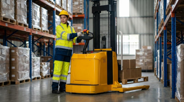
Straddle stacker lifts use a compact hydraulic powertrain, guided mast, and straddle base to move and stack palletized loads in tight aisles. Understanding how the hydraulic circuit, mast structure, and load support elements interact explains how a straddle stacker lift works from pedal or tiller input through to controlled fork motion.
This article breaks down the hydraulic powertrain and lift control, details mast, chain, and stability engineering, and examines fork geometry, straddle bases, and attachments. It then links these design choices to lifecycle risks, helping engineers and fleet owners specify, maintain, and troubleshoot stackers for safe, efficient warehouse operation.
Hydraulic Powertrain And Lift Control
Hydraulic powertrains answered the core question “how does a straddle stacker lift work” by converting mechanical or electric input into high-pressure fluid power. The hydraulic circuit drove the mast cylinders, controlled lift speed, and held loads at height under varying operating conditions. Effective lift control depended on correct component sizing, clean fluid, and calibrated valves that matched the stacker’s rated capacity and duty cycle.
Core Components Of The Hydraulic Circuit
The hydraulic circuit in a straddle stacker typically included a reservoir, pump, relief valve, control valve block, cylinder, filters, and hoses. Manual units used a foot or hand pump, while powered stackers used an electric motor-driven gear or vane pump sized around the lift motor rating, for example 1.5 kW at 12 V. The reservoir stored enough oil to feed the cylinder volume plus return flow without aeration, with headspace to accommodate thermal expansion. A relief valve limited maximum system pressure to protect the mast, forks, and chassis from overload. Directional and lowering valves routed flow to the lift cylinder and controlled descent. Return-line and suction filters maintained oil cleanliness, which reduced wear in pumps and valves and stabilized lift performance. Hoses and rigid lines connected these components and had to withstand peak working pressure with an adequate safety factor, typically at least 3:1 relative to relief pressure.
How Pressure Generates Lift And Controls Speed
In operation, the pump converted mechanical or electrical energy into hydraulic flow, which entered the lift cylinder. Pressure built when the forks met the load, and the product of pressure and cylinder piston area generated the lifting force. For example, a 2,000 lb (≈9 kN) rated counterbalanced stacker with a 50 mm bore cylinder required system pressures on the order of several tens of megapascals to raise full load safely. Lift speed depended on flow rate and cylinder area, so manufacturers matched pump displacement and motor power to achieve typical unloaded and loaded speeds, such as 0.13 m/s at 1,500 lb and 0.10 m/s at 2,700 lb. Flow-control orifices and proportional lowering valves smoothed descent and prevented sudden drops when the operator commanded lowering. Check valves and load-holding valves locked fluid in the cylinder chamber when the control handle returned to neutral, which answered a key aspect of “how does a straddle stacker lift work” by explaining how it held a pallet at height without continuous pump operation.
Common Hydraulic Failures And Diagnostics
Typical hydraulic faults in straddle stackers included slow or no lift, erratic motion, and fork drift under load. Low oil level or aerated fluid often caused slow lifting or spongy response; technicians checked the reservoir, topped up with the specified hydraulic oil, and bled air by cycling the mast through full stroke without load. Internal leakage through worn cylinder seals, scored piston rods, or damaged check valves led to forks creeping down even with the handle in neutral. External leaks at hose fittings, pump seals, or valve blocks left visible oil traces and reduced available pressure. A clogged suction filter or failing pump caused cavitation noise and weak lifting, which operators could detect as a strained or irregular pump sound. On electric stackers, low battery voltage or poor electrical connections produced symptoms similar to hydraulic failure, so diagnostics always started with verifying battery state, fuses, and motor operation before deeper hydraulic disassembly.
Energy Efficiency And Fluid Selection Trends
Hydraulic efficiency in straddle stackers depended on pump design, valve strategy, and fluid condition. Gear pumps with fixed displacement dominated compact stackers, but their continuous bypass losses at relief pressure reduced efficiency during standby. To answer efficiency aspects within “how does a straddle stacker lift work,” designers minimized throttling losses by sizing pumps to the typical duty cycle and using well-matched flow-control valves. Correct fluid viscosity reduced internal leakage while limiting friction losses, so OEMs specified ISO VG grades suitable for the operating temperature range of warehouses and loading docks. Fire-resistant water-glycol fluids, approved by industrial insurers, improved safety in high-risk areas but required compatible seals and slightly different maintenance practices. Cleanliness control through filtration and scheduled oil changes preserved valve metering characteristics and maintained consistent lift speed over the stacker’s life. Emerging trends included low-toxicity, biodegradable fluids for environmentally sensitive sites and higher-efficiency motor-pump units that reduced energy consumption per tonne-meter of lifted load.
Mast Structures, Chains, And Stability
The mast structure defines how a counterbalanced stacker carries vertical loads and maintains stability. When engineers ask “how does a straddle stacker lift work,” the mast, chain system, and stiffness limits form a large part of the answer. Correct mast selection and maintenance directly affect rated capacity, lift height, and residual stability. Design choices must align with pallet heights, aisle geometry, and the required stacking levels.
Single-Stage Vs. Telescopic Mast Designs
Single-stage masts used a fixed outer channel with one moving inner carriage section. They typically offered lift heights up to roughly 1.8 m, which suited low-level stacking and feeding workstations. Telescopic masts incorporated two or more nested channels that extended sequentially, increasing maximum lift height beyond 3 m in compact frames. This design allowed higher racking while keeping the collapsed mast height low for doorway clearance and transport.
In straddle stackers, single-stage masts provided higher inherent stiffness because only one moving section experienced bending. They worked well where operators lifted dense loads to moderate heights and needed predictable deflection. Telescopic masts introduced more joints, sheaves, and chain runs, which required tighter tolerances and better lubrication control. Designers compensated with higher-strength steels, larger section moduli, and carefully located cross-bracing to control column buckling and sway.
From a “how does a straddle stacker lift work” perspective, mast type governed the hydraulic cylinder arrangement and chain reeving. Single-stage designs often used a direct-acting cylinder that pushed the carriage. Telescopic designs frequently used one or two cylinders with chain or rope multiplication, where cylinder stroke translated into greater fork travel. Engineers balanced lift speed, stroke length, and available chassis space when choosing between mast types.
Chain, Roller, And Guide Systems In The Mast
Lift chains transmitted force from the hydraulic cylinder to the carriage and upper mast stages. Dual leaf chains with high yield strength, around 36.7 kN or higher per strand, offered redundancy and reduced stress per link. Heavier-capacity straddle stackers sometimes used dual roller chains to handle higher dynamic loads at maximum lift height. Correct chain pitch and width selection minimized elongation under repeated load cycles.
Guide rollers carried lateral and fore-aft loads between mast channels. These rollers usually ran on hardened tracks integrated into the mast profiles. Proper roller diameter and bearing selection limited contact stress and reduced friction, which supported smoother vertical motion and lower energy consumption. Engineers specified polyurethane or steel rollers depending on required stiffness, noise limits, and environmental conditions.
Side guides and wear pads controlled clearance between moving and fixed mast sections. Too much clearance increased mast sway and misalignment of forks relative to the pallet. Too little clearance caused binding, high friction, and roller spalling. Lubrication of chains, sheaves, and roller bearings played a direct role in how reliably a straddle stacker lifted over time. Poor lubrication led to noise, jerky motion, and accelerated wear of pins, bushings, and tracks.
To answer “how does a straddle stacker lift work” in diagnostic terms, technicians inspected chains for elongation, corrosion, and cracked plates. They checked roller free rotation and looked for flat spots that indicated overload or impact. Any chain stretch beyond roughly 2–3% or visible roller damage reduced safe working load and required replacement. Regular tension checks ensured equal load sharing between parallel chains, which maintained vertical tracking of the carriage.
Deflection, Load Charts, And Stability Limits
Mast deflection governed how much the forks tilted forward or sideways under rated load at full height. Engineers calculated deflection using mast section stiffness, chain elasticity, and carriage clearances. Excessive deflection increased the effective load center and reduced the stability margin of the straddle base. It also made pallet entry and extraction less precise at upper rack levels.
Load charts translated structural and stability calculations into practical limits for operators. Charts typically specified maximum capacity at a defined load center, for example 1,000 kg at 600 mm, and derated capacity at greater heights. As mast height increased, allowable load decreased to keep the combined center of gravity within the stability triangle formed by the wheels and straddle legs. Operators who understood these charts understood a core part of how a straddle stacker lift worked safely.
Stability limits also depended on straddle width, wheelbase, and floor conditions. Narrow bases or high loads with offset centers increased rollover risk during travel and turning. Engineers used finite element analysis and tilt tests to verify that the machine resisted tipping under defined side and longitudinal slopes. Safety factors covered dynamic effects such as braking, acceleration, and uneven floors.
In practice, technicians monitored for permanent mast bending, cracked welds, and elongated bolt holes as signs that design limits had been exceeded. Any visible twist or non-parallelism between mast channels indicated loss of stiffness and required immediate assessment. Maintaining correct mast alignment, chain tension, and adherence to the published load chart ensured that the theoretical stability model matched real-world behavior. This alignment closed the loop between design calculations and the actual way a battery-powered stacker lift worked in daily warehouse operations.
Fork Geometry, Straddle Base, And Load Support
Fork geometry, straddle base layout, and auxiliary load supports determine how a counterbalanced stacker transfers forces into the mast and floor. These elements explain a crucial part of how does a straddle stacker lift work in real warehouses. Correct matching of fork dimensions, base width, and pallet type governs stability, maneuverability, and component life.
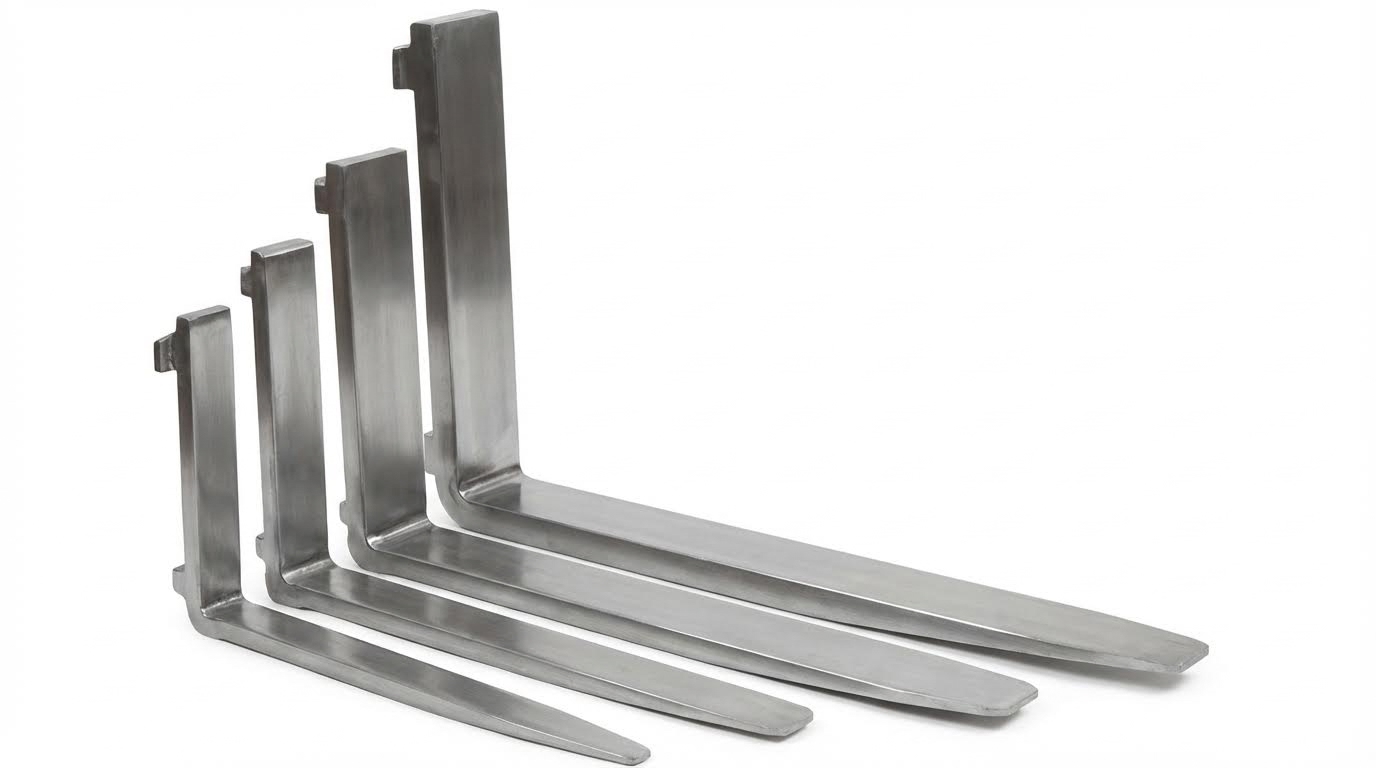
Fork Dimensions, Load Center, And Pallet Types
Fork length, width, and thickness define the structural capacity and usable load center. Typical electric straddle stackers use fork lengths from 0.9 m to 1.2 m with adjustable spacing from about 0.33 m to 0.75 m. Engineers rate capacity at a specified load center, often 400 mm, 450 mm, or 600 mm from the fork heel. If the load center shifts forward beyond this value, effective capacity drops and mast bending moments increase.
Fork thickness and section modulus must resist bending under rated loads, for example 1,200 kg or 1,500 kg. A common configuration uses fork thickness around 65 mm and individual fork widths near 150 mm for medium-duty units. Closed-deck pallets, block pallets, and Euro pallets require different fork entry clearances and tip chamfers. When asking how does a straddle stacker lift work with mixed pallets, the answer lies in pairing fork geometry with pallet opening height and stringer spacing.
Shorter forks improve maneuverability in narrow aisles but reduce support for long or flexible loads. Longer forks allow double-pallet handling but demand higher torsional stiffness in the carriage and mast. Engineers must balance fork length, section size, and steel grade to limit deflection while maintaining acceptable truck weight and cost.
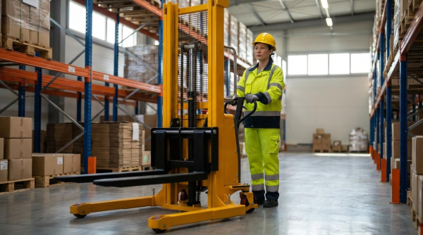
Fixed Vs. Adjustable Straddle Bases And Wheels
The straddle base carries the vertical reaction loads from the mast and stabilizes the stacker laterally. Fixed bases use welded or bolted frames with a constant inside dimension, for example 690 mm or 1,070 mm between straddles. Adjustable bases employ telescoping or bolted side frames that change the internal opening, often from about 0.9 m to 1.3 m. This adjustability lets one truck handle both narrow Euro pallets and wider industrial pallets while retaining clearance around pallet legs.
From a functional viewpoint, how does a straddle stacker lift work without tipping when side loads act? The answer includes wheel layout and base width. Load wheels sit near the fork tips or under the straddles and carry a large portion of the lifted mass. Steering wheels, typically polyurethane with diameters around 100 mm to 200 mm, support the rear and provide directional control. Wider straddle spacing increases the roll moment of inertia and raises the allowable side offset of the load before instability.
Wheel material selection affects rolling resistance, floor wear, and vibration transmission into the mast. Polyurethane wheels with precision bearings reduce starting effort and noise while surviving point loads from uneven floors. Engineers size axles and brackets to handle combined vertical, lateral, and impact loads, especially when turning with elevated pallets.
Attachments, Custom Platforms, And Use Cases
Attachments and platforms adapt straddle stackers for non-standard loads such as drums, coils, dies, and fixtures. Slip-on platforms can mount over existing forks, with typical sizes like 600 mm × 600 mm, 800 mm × 760 mm, or 1,000 mm × 900 mm. These platforms shift the effective load center and often increase the projected area, which raises mast bending and base reactions. Designers therefore derate the Safe Working Load when using extended platforms or cantilevered attachments.
Examples include boom attachments with hooks for lifting slung loads, cylindrical rams for roll handling, and drum grabbers for 200 L drums. Each attachment introduces new load paths and potential eccentricities relative to the straddle base. When evaluating how does a straddle stacker lift work with these accessories, engineers consider worst-case load positions, including off-center and elevated conditions. Custom platforms may incorporate non-slip surfaces, bridge plates, or cutouts to interface with presses, conveyors, or racks.
Attachment interfaces usually rely on fork pockets, pin-on mounts, or quick-change carriages. Proper locking mechanisms prevent accidental disengagement during travel or tilt. Documentation must state the combined capacity of truck plus attachment at defined load centers to remain compliant with safety standards.
Safety Devices, SWL Compliance, And Standards
Safety devices around the forks and straddle base ensure that structural design limits translate into safe field operation. The Safe Working Load (SWL) plate states rated capacity, load center, and maximum lift height. Operators must not exceed these values, especially when using long forks, wide bases, or heavy attachments. Overload can cause excessive fork deflection, mast bending, or loss of stability.
Mechanical or electronic overload protection can limit hydraulic pressure or cut lift when the load exceeds design thresholds. Flow control valves regulate lowering speed so that the load descends smoothly even under maximum rating. Safety interlocks may prevent travel with the forks above a defined height, reducing the risk of overturning. For anyone analyzing how does a straddle stacker lift work safely, these control layers are as important as steel dimensions.
International and regional standards specify design and test requirements for industrial trucks and lifting devices. These standards cover static and dynamic stability tests, proof load testing, labeling, and guarding. Regular inspections verify fork wear, crack initiation at welds, wheel condition, and chain elongation. Maintaining SWL compliance over the lifecycle demands periodic derating or component replacement when wear, corrosion, or damage reduces structural capacity.
Summary: Key Design Choices And Lifecycle Risks
Understanding how does a straddle stacker lift work requires viewing the machine as an integrated system. The hydraulic powertrain, mast structure, and load support geometry interact to convert fluid pressure into controlled vertical motion while keeping the center of gravity inside a stable straddle footprint. Design choices on cylinder sizing, mast type, chain routing, fork dimensions, and straddle width therefore set the limits for capacity, lift height, maneuverability, and residual stability. Over the lifecycle, these same decisions drive maintenance demand, downtime risk, and total cost of ownership.
From a technical perspective, the hydraulic circuit defined the available lifting force and speed profile, while flow control elements governed smooth lowering and energy efficiency. Incorrect fluid selection, contamination, or seal wear created pressure loss, drift, and overheating, so robust filtration and clear maintenance intervals were critical. Mast selection between single-stage and telescopic types balanced compact lowered height against maximum lift, with chain, roller, and guide design controlling friction, deflection, and noise. Load charts and stability calculations linked these structural choices to safe working load across the full lift range.
On the load support side, fork length, section modulus, and adjustable fork spacing had to match pallet design and load center distances to avoid overload at height. Fixed or adjustable straddle bases determined which pallet footprints could be handled and how close the counterbalanced stacker could approach racking, while wheel type and layout set turning radius and floor loading. Attachments and custom platforms extended functionality but introduced new bending and torsion paths that required explicit SWL marking and compliance with relevant standards. Across the lifecycle, operators and engineers needed to monitor hydraulic performance, mast wear, and structural fatigue, applying preventive inspections and timely component replacement to keep the original design safety margins intact as the equipment aged.