Straddle stackers played a critical role in high-density warehouses, retail backrooms, and light manufacturing lines. This article examined their core design and operating principles, contrasted them with pallet jacks and counterbalance trucks, and mapped typical performance envelopes for narrow-aisle work. It also reviewed safety engineering, operator training, and regulatory expectations, including accident modes, inspection routines, and lockout/tagout practices.
Beyond safe operation, the discussion covered maintenance strategies, diagnostics, and energy management across the equipment lifecycle, from daily checks to quarterly overhauls and fault troubleshooting. Finally, it provided practical selection and implementation guidelines so plants could match stacker specifications, safety programs, and maintenance regimes to their throughput, aisle geometry, and rack layouts.
Core Design And Operating Principles Of Straddle Stackers

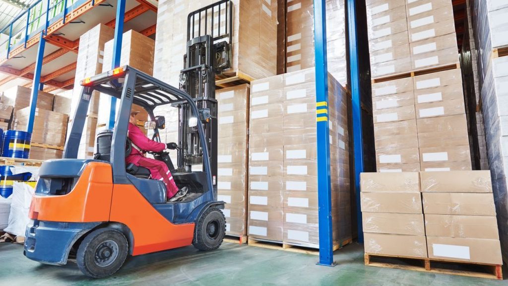
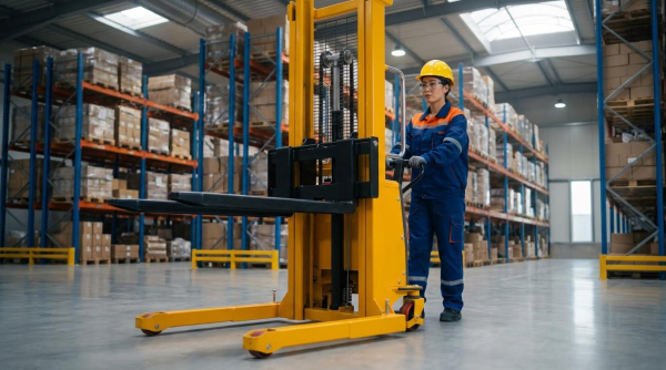
Straddle stackers operated as pedestrian-controlled lift trucks optimized for narrow aisles and second-tier racking. Their design combined compact chassis dimensions, outrigged straddle legs, and a high-lift mast to position loads where a pallet jack could not reach. Engineers used these machines where full counterbalance forklifts were unjustified or physically constrained. Understanding their comparative role, structural layout, and stability behavior was essential for safe, efficient deployment.
Straddle Vs. Pallet Jacks And Counterbalance Trucks
Straddle stackers bridged the gap between low-lift pallet jacks and ride-on counterbalance trucks. Unlike electric pallet jacks, they lifted pallets to heights up to roughly 3–4.8 m, enabling storage on upper rack levels. Their straddle legs supported the load from the sides, which reduced the need for a heavy counterweight and allowed a narrower, lighter chassis. Compared with counterbalance forklifts, they achieved smaller turning radii and better maneuverability in aisles often below 2 m wide. However, they required compatible pallets or load bases that could sit between or over the straddle legs.
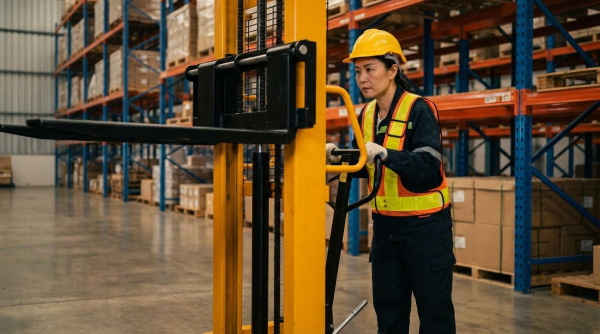
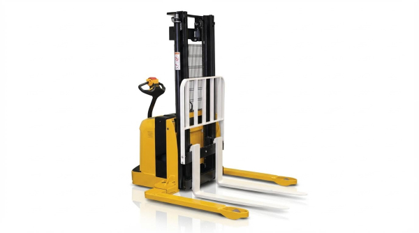
Key Components: Mast, Straddle Legs, And Drive System
The mast typically used rolled steel channels with thick inner rails to maintain capacity at height and resist bending. Lift chains, hydraulic cylinders, and a carriage with forks translated hydraulic pressure into vertical motion, with optional duplex or triplex masts for higher reach. Straddle legs extended laterally from the chassis and carried load wheels, forming a wide wheelbase that improved lateral stability and reduced tip-over risk during turning and lifting. The drive system usually combined a 24 V brushless AC traction motor, an electric pump motor, and an inverter or motor controller that regulated torque, acceleration, and regenerative braking. An ergonomic tiller or control handle integrated travel, lift, lower, horn, and emergency reverse functions to support precise low-speed positioning.
Load Moment, Stability Triangle, And Narrow-Aisle Dynamics
Stacker stability relied on the relationship between load weight, load center distance, and the geometry of the support points, often described as the stability triangle. Engineers evaluated load moment as the product of load and horizontal distance from the front axle or pivot line; increasing either variable pushed the combined center of gravity toward the triangle boundary. High lifts, off-center pallets, or extended loads above the second tier reduced the stability margin and increased tip-over probability. In narrow aisles, operators needed to minimize steering input with elevated loads, keep forks low while traveling, and avoid lateral impacts that could shift the center of gravity outside the support polygon. Floor flatness, rack clearances, and turning radii all influenced safe maneuvering envelopes.
Typical Performance Specs And Application Envelopes
Industrial straddle stackers typically offered rated capacities between 1 000 kg and 1 800 kg at standard load centers, often 600 mm. Maximum fork heights ranged from about 3.8 m to 4.8 m, with some models designed for approximately 4.8–4.9 m reach to access high shelving. Travel speeds under full load were usually near 5–6 km/h, balanced against stopping distances and pedestrian safety. Chassis widths around 0.8–0.85 m and steering arcs near 180–190° supported tight turning radii for aisles slightly wider than the pallet length plus clearance. These characteristics made straddle stackers suitable for beverage distribution, general manufacturing, and retail backrooms where vertical storage density and pedestrian-scale equipment were priorities.
Safety Engineering, Training, And Regulatory Compliance
Safety engineering for straddle stackers relied on a structured understanding of failure modes, human factors, and equipment limits. Facilities used this framework to align with occupational safety regulations and internal standards. Effective programs combined engineered safeguards, procedural controls, and continuous operator training. Digital tools increasingly supported documentation, monitoring, and verification of compliance activities.
Primary Accident Modes And Engineering Controls
Historical data showed four dominant accident categories for straddle stackers: tip-over, loss of steering control, falling loads, and collisions. Tip-over events typically occurred when operators exceeded capacity, mispositioned loads, or operated on uneven floors or ramps. Engineering controls addressed these risks through low center-of-gravity chassis, wide straddle legs, stability triangle–based design, and speed or lift-height interlocks. Regenerative and service braking, emergency reverse switches, horn systems, and mast guards further reduced collision and load-fall hazards. Facilities enhanced these controls with marked pedestrian zones, speed-limited areas, and impact-resistant rack protection.
Pre-Shift Inspection And Lockout/Tagout Practices
Pre-shift inspections functioned as the primary barrier against unsafe operation of straddle stackers. Checklists typically covered wheels and tires, forks, mast, chains, rollers, guards, carriage, hydraulic cylinders and hoses, handle, steering, brakes, warning lights, horn, and emergency stop devices. Operators verified lift and lower functions, checked for leaks, deformation, corrosion, and abnormal noises, and confirmed battery charge and cabling integrity. Any defect that affected safety required immediate removal from service and initiation of a lockout/tagout procedure. Lockout/tagout isolated the electrical and hydraulic energy sources, applied physical locks, and attached clear tags until qualified personnel completed repairs and documented the return-to-service test.
Load Handling, Balancing, And Data Plate Interpretation
Safe load handling depended on a correct understanding of capacity, load center, and the stability triangle. Operators read the manufacturer’s data plate to determine rated capacity at a specified load center distance and maximum lift height. Exceeding the rated load or extending the load center, for example with long pallets or overhanging product, increased the load moment and reduced stability. Best practice placed the load symmetrically on both forks, fully supported, with the heaviest mass closest to the mast and within the straddle legs when possible. Facilities defined procedures for unusual loads, such as tall, offset, or shrink-wrap-only pallets, and restricted travel speed and lift height to maintain a safe margin against tip-over and falling loads.
Integrating Video Training And Digital Safety Programs
Short, focused safety videos for straddle stackers and related equipment formed a practical foundation for operator training. These modules typically covered hazard recognition, inspection steps, data plate use, and correct load handling in narrow aisles. Facilities embedded videos into blended programs that included instructor-led sessions, written assessments, and hands-on evaluations on the actual truck type. Digital safety platforms then tracked training completion, refresher cycles, and incident history at the operator level. Some sites integrated pre-shift inspection apps, near-miss reporting, and telematics data to create feedback loops that continuously updated training content and targeted coaching toward recurring unsafe behaviors or high-risk zones in the facility.
Maintenance Strategies, Diagnostics, And Technology Trends
Maintenance strategies for straddle stackers relied on structured intervals, standardized checklists, and data-driven diagnostics. Plants used tiered daily, weekly, monthly, and quarterly routines to control failure risk and lifecycle cost. Electric architectures, battery systems, and control electronics required disciplined inspection and documentation. Emerging digital tools, including telematics and AI-based analytics, started to transform how facilities monitored condition, predicted failures, and optimized utilization.
Preventive Maintenance Intervals And Checklists
Effective preventive maintenance for straddle stackers combined time-based and hour-based intervals. Daily checks typically covered visual inspection of hydraulic cylinders and hoses for leaks or cracks, mast assemblies for deformation or corrosion, and forks for bending or damage. Operators also verified wheel condition, warning lights, horn, emergency stop devices, and basic lift and lower functions before use. Weekly or 50-hour tasks usually focused on brake system behavior, steering gear cleanliness, and brake clearance, with values held within 0.2–0.8 mm to maintain predictable stopping performance.
Monthly or 200-hour inspections expanded the scope to structural integrity of chassis, fasteners, linkages, and fork carriages, plus detailed checks of chains, rollers, and guards. Technicians inspected hydraulic oil levels against mast height requirements and checked for cylinder leakage or hose sweating. Electrical checks included electrolyte level, battery connections, key switches, contactors, micro switches, controllers, and wiring harnesses. At roughly 600 operating hours, maintenance programs repeated these tasks and added deeper component inspections, such as motor carbon brush and commutator wear, contactor resurfacing, and brake pad cleaning or replacement.
Maintenance checklists worked best when they were specific, measurable, and tied to work orders. Failed inspection items required immediate documentation with notes or photos and formal fault reporting. Plants typically locked and tagged out affected stackers until repairs were completed and verified. Consistent use of standardized forms improved regulatory compliance and created a data trail for reliability analysis and continuous improvement.
Troubleshooting Hydraulic, Drive, And Control Faults
Systematic troubleshooting started with clear symptom definition and basic safety isolation, including power-off and lockout procedures. For drive issues where the counterbalanced stacker could not move, technicians first checked control circuit fuses, main fuses, power switches, and battery connections. Blown fuses, burned contacts, or loose terminals frequently caused no-move conditions and required replacement or tightening. If the stacker moved only forward or only reverse, investigations focused on individual drive contactors and control boards for stuck or burned contacts.
Uncontrolled motion, such as inability to stop, indicated serious contactor or control failures. In these cases, operators had to cut power immediately and remove the unit from service. Hydraulic faults, such as forks that would not lift, often traced to overload operation, insufficient hydraulic oil, low battery voltage, or malfunctioning pump motors. Internal leakage in lift cylinders, incorrect overflow valve settings, or damaged lift switches also caused slow or no-lift behavior. Technicians verified load against the data plate, checked oil level, confirmed battery charge, and then measured hydraulic pressure and flow.
Controls and sensors required careful diagnosis because intermittent faults were common. Incorrect handle position, damaged micro switches, or faulty emergency switches could block travel or lifting even when major components were intact. Standard practice used a progression from simple to complex checks: visual inspection, mechanical free movement, electrical continuity, and finally functional testing under load. Documented troubleshooting trees reduced downtime and supported consistent repair quality across shifts and sites.
Energy Systems, Charging, And Runtime Optimization
Straddle stackers used 24 V electrical systems with traction and pump motors sized for narrow-aisle duty cycles. Daily routines included checking battery charge level and electrolyte height, then topping up with purified water after full charging if required. Operators inspected battery covers, cables, and connectors for damage or corrosion to prevent voltage drops and heat buildup. Specific gravity measurements after full charge, for example around 10.67 lb/gal for certain electrolyte formulations, confirmed correct state of charge and battery health.
Hydraulic oil volume correlated with mast height, so technicians maintained defined fill levels, such as approximately 5–6 L for lift heights between 2.5 m and 3.5 m. Weekly tasks included cleaning steering gear, verifying brake clearance, and removing oil and dust that increased drag and energy consumption. Monthly and quarterly checks validated electrical contact quality, polished contactors, and assessed motor wear, all of which affected current draw and runtime. Facilities that conducted power studies over 2–4 weeks collected data on run-time, idle time, available charge, and amp-hours to understand real energy demand.
Runtime optimization strategies balanced charging patterns, shift scheduling, and fleet sizing. Opportunity charging during breaks helped maintain state of charge without deep cycling, extending battery life. Advanced controllers and regenerative braking recovered energy during deceleration and lowering, reducing net power use. Plants used collected energy data to right-size battery capacity, adjust charger placement, and identify underutilized or overstressed trucks, driving both cost reduction and higher availability.
AI, Telematics, And Digital Twins For Stackers
Telematics systems for straddle stackers captured operating hours, travel distance, lift cycles, impacts, and battery metrics. This data supported condition-based maintenance by triggering service when vibration levels, current draw, or fault codes exceeded thresholds. Fleet managers used dashboards to compare utilization across trucks, identify chronic problem units, and enforce access control or speed limits by operator or zone. Integration with safety programs allowed correlation of near-miss events, impacts, and training records for targeted interventions.
AI-driven analytics processed historical maintenance and sensor data to predict failures before they caused downtime. Algorithms detected patterns such as rising contactor temperatures, increasing motor current at constant load, or growing hydraulic cycle times that signaled emerging issues. Plants then scheduled repairs during planned outages instead of reacting to breakdowns. Digital twins, representing stackers as virtual models, enabled simulation of duty cycles, aisle layouts, and energy usage scenarios. Engineers evaluated how different mast heights, battery capacities, or shift patterns affected reliability and total cost of ownership.
These technologies also improved compliance and documentation. Automated logging of inspections, faults, and lockout events reduced manual paperwork and audit risk. Over time, combined AI and telematics data refined preventive maintenance intervals, moving from rigid time-based schedules to risk-based strategies. The result was a gradual shift from reactive and calendar-driven maintenance toward predictive, data-informed lifecycle management for straddle stacker fleets.
Summary And Practical Selection Guidelines For Plants
Straddle stackers operated in warehouses and plants offered a compact, high-lift solution for narrow aisles where counterbalance trucks were impractical. Their design combined a straddling leg geometry, high-reaching masts, and electric drive systems to handle palletized loads up to roughly 1 800 kg within confined rack layouts. Safety engineering centered on the stability triangle, load moment limits, and separation of pedestrians from operating zones, supported by structured training and pre‑shift inspections. Effective lifecycle management depended on disciplined preventive maintenance, accurate diagnostics of hydraulic and electrical faults, and optimized charging strategies for 24 V traction batteries.
When selecting straddle stackers for a plant, engineers needed to start from the application envelope rather than the catalog rating. Key parameters included maximum rack height, minimum aisle width, pallet type, and typical load mass and center of gravity. The chosen model’s rated capacity at the required lift height and load center had to exceed the worst‑case load, as documented on the data plate. Turning radius and straddle leg clearance had to match aisle geometry, floor flatness, and any pit or dock interfaces. Plants with multi‑shift operation benefited from higher‑efficiency AC drive systems, regenerative braking, and battery capacities sized using power studies that measured run‑time, idle time, and amp‑hour draw.
From a risk perspective, facilities had to evaluate historical incident data and prioritize features that mitigated tip‑over, loss of steering control, falling loads, and collisions. This evaluation supported investment in engineering controls such as optimized mast and chassis stiffness, enhanced braking systems, and clear operator visibility through flat‑face masts. Digital tools, including telematics and video‑based safety programs, enabled monitoring of impacts, overload events, and unsafe driving patterns, which informed targeted retraining. Future developments were expected to increase sensor integration, predictive maintenance using machine data, and closer coupling between digital twins and real‑time fleet management, but plants still needed robust fundamentals: trained operators, enforced procedures, and a documented maintenance regime.