Walkie stacker capacity defined how much a lift stacker could safely hold, lift, and transport in real warehouses. This article examined typical walkie stacker capacities and specifications, then explained the engineering factors that derated the headline rated load. It also covered how to select and manage walkie stackers in practice by reading capacity plates, matching loads to pallets and racking, and using maintenance and digital tools to preserve capacity. Finally, it summarized how to use the rated load safely so that real-world operation stayed within engineering and regulatory limits.
Typical Walkie Stacker Capacities And Specs
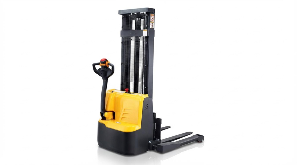
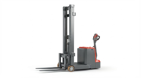
When engineers ask “how much can a walkie stacker hold,” they refer to its rated capacity under defined test conditions. Typical walkie stacker capacities and specs depend on load center, lift height, and geometry, not just motor size. This section explains common capacity ranges, standard load centers, mast effects, and key dimensions so you can match stackers to real warehouse constraints.
Common Capacity Ranges And Use Cases
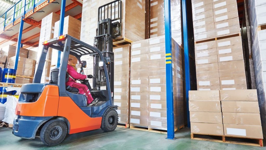
Walkie stackers typically hold between 1,000 kg and 2,000 kg at the rated load center, with some designs reaching 3,000 kg to 4,000 kg. In imperial units, that range equals roughly 450 kg to 1,800 kg for common pedestrian-operated units, and up to 2,000 kg for heavier-duty straddle configurations. Light-duty walkie stackers around 1,000 kg suit low-throughput zones, small manufacturing cells, and occasional pallet moves. Mid-range units around 1,500 kg to 2,000 kg fit most warehouse pallet handling, dock work, and feeder operations to conveyors or production lines. Higher-capacity walkie reach or straddle stackers handle dense racking, heavier packaging, or mixed-size pallets where reserve capacity improves safety margins. Engineers should always check whether the quoted capacity applies at the required lift height and load center, not just at ground level.
Load Center Standards And Their Implications
Rated capacity answers “how much can a walkie stacker hold” only at the specified load center. Standards typically use 500 mm or 600 mm load centers, measured from the fork heel to the load’s center of gravity. If the actual load center shifts beyond that value, the effective capacity drops because the overturning moment increases. Long pallets, overhanging loads, or stacked containers push the center of gravity forward and derate the safe load. Engineers should compare pallet length and typical load geometry against the rated load center and consult capacity charts for extended forks or attachments. Using a stacker at the wrong load center without derating calculations increases tipping risk, especially at higher lifts or on grades.
Lift Height, Mast Types, And Stability Limits
Lift height heavily influences how much a walkie stacker can safely hold at the top of the stroke. Standard models lift to roughly 2,500 mm, while high-lift triplex masts reach about 5,500 mm. As height increases, the load’s center of gravity rises and shifts along the mast, increasing overturning and deflection. Manufacturers therefore rate capacity at a reference height and often reduce allowable load at maximum elevation. Single-stage and duplex masts usually maintain higher capacity across their range, while triplex masts trade some high-lift capacity for greater reach. Capacity plates or load charts specify how much the stacker can hold at intermediate and maximum heights. Engineers should select mast types based on racking elevations and required residual capacity at top beam level, not only on maximum stated lift height.
Key Dimensions: Wheelbase, Aisle Width, And Radius
Geometric parameters define both maneuverability and how much a walkie stacker can hold without compromising stability. Typical wheelbases range from about 1,210 mm to 1,610 mm; a longer wheelbase improves longitudinal stability but increases turning radius and aisle requirements. Minimum turning radii often fall between 1,460 mm and 2,290 mm, depending on chassis length and whether support legs or pedals extend. Aisle width requirements tie directly to pallet size and turning radius, with common specification values up to roughly 3,900 mm for 90-degree stacking with standard pallets. Shorter wheelbase walkie stackers work better in very narrow aisles but may require tighter derating margins at high lifts or with long loads. When engineers evaluate “how much can a walkie stacker hold” for a given site, they must consider whether the required wheelbase and aisle width for stability still fit the existing layout.
Engineering Factors That Derate Rated Capacity
Rated capacity answered the question “how much can a walkie stacker hold” only under ideal test conditions. Real sites rarely matched those conditions, so effective capacity usually dropped below the plate value. Engineering factors such as load position, lift height, surface quality, wheel layout, and powertrain temperature all reduced the safe working load. Understanding these derating mechanisms allowed engineers and safety managers to set realistic limits and avoid tip‑over or structural overload.
Load Center Shift, Height, And Tipping Moment
Rated capacity for lift stacker typically referred to a 1000–2000 kg load at a 500 mm or 600 mm load center. This rating assumed the load center sat directly above the fork heel and at a defined reference height. When the load center moved forward, the overturning moment increased as M = W × d, where W was load and d was horizontal distance. Even a 100 mm shift could reduce how much a walkie stacker could hold by several hundred kilograms according to capacity charts.
Lift height also affected tipping moment. As the mast extended toward 2500–5500 mm, the combined center of gravity of truck and load rose. The stability triangle from the wheel contact points stayed fixed, so the margin to the tipping line shrank. Manufacturers therefore published capacity curves that decreased with height, especially for triplex masts at maximum elevation.
Operators often underestimated the impact of tall, offset, or unevenly packed loads. A high, forward‑biased center of gravity behaved worse than a compact cube at the same mass. Engineering controls such as load backrests and strict load center limits helped maintain stability, but the primary safeguard remained respecting the derated values from the load chart, not just the headline rating.
Floor Flatness, Friction, And Site Conditions
Rated capacity assumed a level, dry, and clean floor with controlled flatness. In practice, slabs often deviated by ±3–5 mm per meter, included joints, or had local settlement. When a walkie stacker crossed a depression or high spot, one support wheel could unload while another overloaded, shifting the instantaneous stability triangle and increasing tip‑over risk. Engineers therefore recommended additional derating on poor floors, especially near racking or pits.
Friction between wheels and floor also limited how much a walkie stacker could hold, particularly on grades of 3–8%. A coefficient of friction μ of at least 0.4–0.6 was desirable for polyurethane tires on concrete. Contaminants such as oil, dust, or water reduced μ, increasing braking distance and reducing drawbar pull. On a 5% slope, a 1500 kg load generated a downslope component of roughly 735 N, which could exceed available traction if the surface was polished or coated.
Ambient conditions further influenced effective capacity. High humidity or condensation degraded floor friction and affected braking consistency. Temperature swings changed tire hardness and hydraulic oil viscosity, which altered dynamic response. From an engineering standpoint, site surveys and periodic floor condition measurements were essential before declaring how much a walkie stacker could safely hold in a given zone.
Tires, Wheel Layout, And Structural Design
Tire material, size, and wear state directly impacted stability and usable capacity. Walkie stackers typically used polyurethane drive and load wheels, for example ϕ210×85 mm load wheels and ϕ230×75 mm drive wheels. As tread wore or flat‑spotted, contact patch geometry changed, which shifted the effective support polygon. Uneven wear between left and right sides introduced tilt, increasing lateral tipping risk at height.
Wheelbase and wheel layout defined the stability triangle and turning behavior. Typical wheelbases ranged from 1210 mm to 1610 mm, with corresponding turning radii from about 1460 mm to 2290 mm. A longer wheelbase improved longitudinal stability but increased turning radius and aisle width requirements. Straddle legs, outrigger spacing, and caster positions all influenced how much a walkie stacker could hold when cornering or braking, since dynamic load transfer moved forces toward the outer wheels.
Structural design of the chassis, mast rails, and fork carriage set the ultimate mechanical limits. Engineers sized sections and welds for rated bending moments and fatigue life with safety factors defined in standards such as ISO 3691 and EN 1726. However, repeated overloading, impacts with racking, or corrosion reduced residual strength over time. Visual inspection alone often missed microcracks, so conservative derating was recommended for equipment with unknown impact history or visible deformation.
Battery State, Motors, And Thermal Limits
Electric walkie stackers generally operated on 24 V batteries with capacities from roughly 180 Ah to 280 Ah. The nameplate rating assumed nominal voltage and adequate battery state of charge. As the battery discharged, terminal voltage sagged under load, reducing current capability of the drive and lift motors. This voltage drop slowed lift speed from typical 75–90 mm/s under full load and could prevent reaching relief valve pressure, effectively lowering how much the walkie stacker could lift to rated height.
Motor and controller heating imposed additional derating. Drive motors of about 1.2–2.2 kW and lift motors of 2.2–3.0 kW generated significant heat during repeated high‑load cycles, especially when handling near the upper capacity range of 1000–2000 kg or when negotiating 3–8% grades. Thermal protection algorithms in modern controllers limited current to protect windings and power electronics. This current limiting reduced available torque and hydraulic pressure, which translated into a lower practical capacity during intensive duty cycles.
Hydraulic oil temperature also played a role. Hot, low‑viscosity oil increased internal leakage across valves and cylinders, reducing effective lifting force at a given pump pressure. Conversely, very cold oil increased pressure spikes and mechanical stress. From a lifecycle engineering perspective, maintaining battery health, ensuring adequate cooling airflow, and designing duty cycles within thermal limits were key to keeping the real‑world answer to “how much can a walkie stacker hold” close to the rated value throughout a shift.
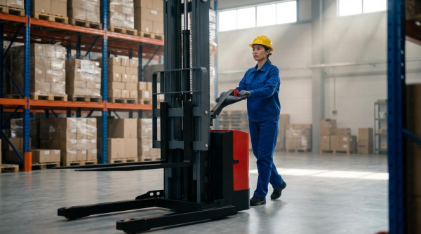
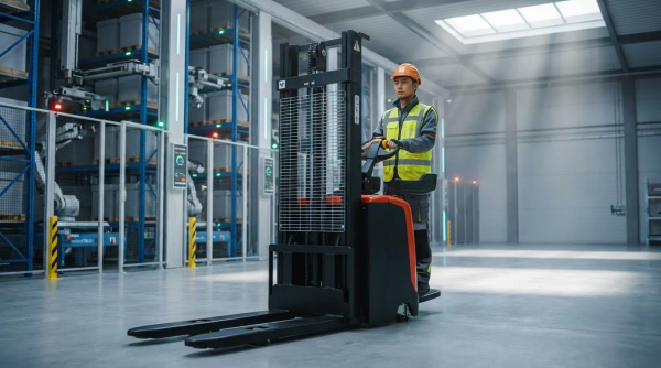
Selecting And Managing Walkie Stackers In Practice
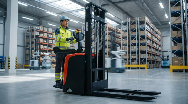
Operators who ask “how much can a walkie stacker hold” need more than a single capacity number. Real-world handling capacity depends on reading the data plate correctly, matching the stacker to pallets and grades, and maintaining the machine so the original rating stays valid. Modern sensing and digital tools also help keep loads within safe limits by monitoring weight, height, and site conditions in real time.
Reading Capacity Plates And Load Charts
The capacity plate answers the core question: how much can a lift stacker hold under defined conditions. It lists rated capacity in kilograms, the reference load center (often 500 mm or 600 mm), and maximum lift height for that rating. Engineers must treat this as a conditional value, not a universal limit. Load charts or tables near the plate usually show how capacity decreases when the load center increases or when lift height rises. For example, a stacker rated 1,600 kg at 500 mm and 3,000 mm lift may only hold about 1,000–1,200 kg at 600 mm and 5,000 mm. Operators should verify that forks, attachments, and mast configuration match the data on the plate. Any attachment that shifts the center of gravity forward, such as a pantograph reach or long custom forks, effectively reduces the safe load, even if the plate shows a higher base rating.
Matching Capacity To Pallets, Racks, And Grades
To decide how much a battery-powered stacker can hold in a given aisle, start from the pallet and racking geometry. Standard warehouse pallets place the load center near 500 mm, but long loads, overhanging cartons, or double-stacked pallets move the center outward. That shift can derate a nominal 2,000 kg stacker to well below 1,500 kg at high lift. Rack beam heights also matter, because capacity usually reduces as lift height approaches 5,000–5,500 mm. Engineers should map typical storage heights and choose a stacker that keeps expected loads within 70–80% of the derated chart values. Site grades and floor slopes further limit real capacity. Typical walkie stackers handle about 3–8% grade when loaded, but that rating assumes the nominal capacity load. On ramps, best practice is to reduce allowable load weight, keep the heaviest loads on the flattest routes, and avoid turning on inclines to preserve lateral stability.
Maintenance Practices To Preserve Capacity
Rated capacity assumes the stacker remains in near-new mechanical condition. Worn forks, elongated chain links, or bent masts change stress paths and reduce safety margins. Routine inspections should check fork heel thickness, fork tip alignment, and mast roller wear against manufacturer limits. Tire condition strongly affects how much a walkie stacker can hold without instability. Polyurethane wheels that develop flat spots or lose tread increase vibration and reduce friction, especially at 3–8% grades. Battery health also influences effective capacity: low voltage under load can slow lift speeds from about 90 mm/s toward the lower end of the design envelope and may prevent full-height lifting of rated loads. Scheduled hydraulic fluid changes, leak checks, and brake inspections keep the system able to control heavy pallets precisely at height. Documented preventive maintenance also supports compliance with safety regulations and internal audit requirements.
Digital Tools, Sensing, And Predictive Monitoring
Modern walkie stackers increasingly incorporate sensors that refine the answer to “how much can a walkie stacker hold right now.” Integrated load cells or pressure-based estimators measure actual load mass at the forks and compare it with the capacity curve for the current mast height. Some systems derate automatically as the mast extends, preventing lifts that exceed safe tipping moments. Height encoders, tilt sensors, and wheel speed sensors feed into controllers that limit travel speed with heavy loads or on detected slopes. Fleet management platforms log overload attempts, hard braking events, and battery discharge patterns. Engineers can analyze this data to adjust training, revise route layouts, or change maintenance intervals before components reach critical wear. Predictive monitoring of motor current, hydraulic pressure, and temperature trends helps keep stackers operating within their designed envelope, so the rated capacity on the plate continues to reflect safe, real-world performance.
Summary: Safely Using Walkie Stacker Rated Load
When engineers and supervisors ask “how much can a walkie stacker hold,” the safe answer always refers to rated capacity, not theoretical strength. Typical walkie stackers held 1000 kg to 2000 kg at a 500 mm or 600 mm load center, with heavy-duty units reaching 3000 kg to 4000 kg in controlled conditions. However, real-world capacity dropped once operators raised the load, shifted the center of gravity, or worked on grades and uneven floors. Safe operation therefore depended on understanding derating mechanisms, not only the headline number on a data sheet.
From a technical standpoint, rated load reflected a stability problem more than a pure strength limit. As lift height increased toward 2500 mm to 5500 mm, the overturning moment grew faster than the counteracting moment from truck mass and wheelbase. Floor flatness, friction coefficient, and aisle geometry further constrained how much a lift stacker could hold without approaching tipping thresholds. Tire stiffness, wheel layout, and mast design all contributed to the allowable combination of weight, load center, and height. Battery voltage sag and motor thermal limits also reduced usable performance during long shifts.
In practice, safe capacity management required disciplined use of capacity plates and load charts, plus matching pallets, rack elevations, and grades to the specific stacker configuration. Facilities that monitored floor condition, maintained tires and hydraulic systems, and enforced battery care preserved close-to-rated performance over the equipment life. Digital load sensing, height sensing, and event logging already supported real-time derating and overload prevention. Future systems would likely integrate predictive analytics, tying maintenance, usage history, and sensor data into dynamic capacity envelopes. The core principle would remain unchanged: treat “how much can a battery-powered stacker hold” as a conditional engineering limit that depends on geometry, environment, and equipment health, not a fixed marketing value.