Forklift pallet handling required precise understanding of rated capacity, load centers, and stability limits to prevent accidents. Engineers and safety managers relied on data plates, load-moment principles, and capacity-derating formulas to match pallets and stacks to the true lifting capability of each truck. At the same time, safe pallet stacking practices, OSHA-compliant storage geometry, and controlled travel and placement techniques determined overall warehouse safety and throughput. This article walked through fundamentals of forklift rated capacity, engineering calculations for pallet loads, safe stacking and handling methods, and concluded with consolidated best practices for industrial operations.
Fundamentals Of Forklift Rated Capacity
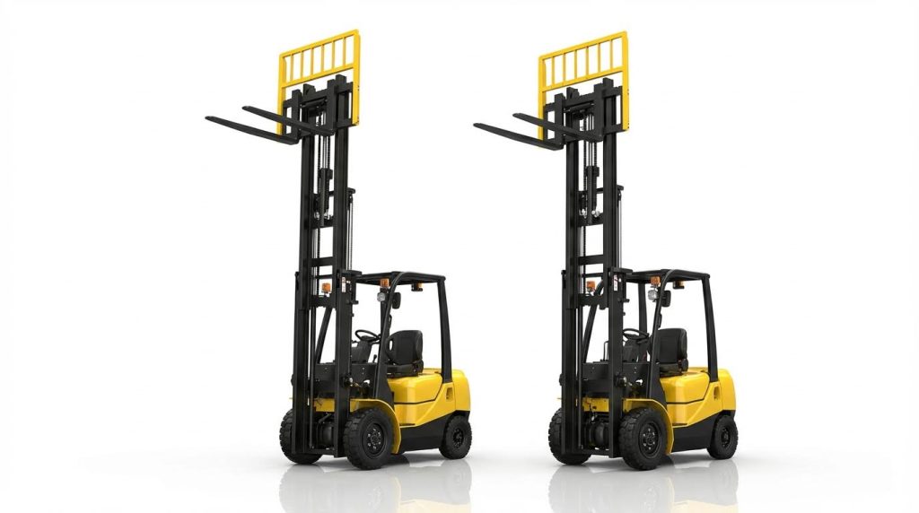
Fundamentals of rated capacity defined how engineers and operators established safe lifting envelopes for forklifts. This section explained the data plate, load center, and stability relationships that governed capacity. It also examined the derating effects of attachments and environmental or terrain conditions. Together, these concepts formed the basis for all subsequent engineering calculations and operating practices in the article.
Reading And Interpreting The Data Plate
The data plate specified the truck’s rated capacity under defined reference conditions. Typical plates listed maximum load, rated load center distance, mast height, and sometimes allowable capacities at different lift heights or mast tilts. The rated capacity assumed an evenly distributed load, located at or within the stated load center, with the mast vertical and forks low, on level ground at low travel speed. When operators used longer pallets or lifted loads further out, the actual safe capacity dropped below the plate rating. Engineers and safety managers used the data plate as the starting point, then applied derating formulas for real-world loads, attachments, and environments. Regulatory bodies such as OSHA and ANSI required that operators never exceed the published capacity values for the relevant configuration.
Load Center, Load Moment, And Stability
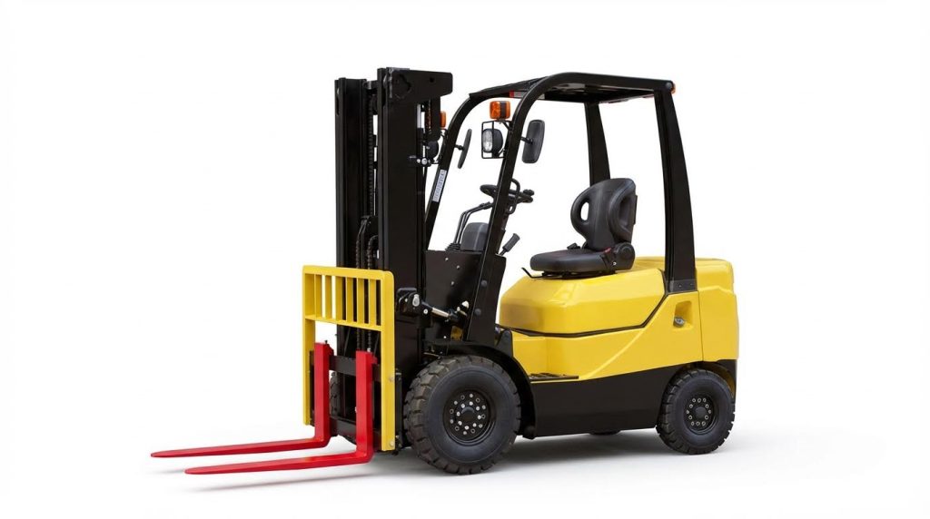
Load center described the horizontal distance from the fork face to the load’s center of gravity. For standard pallets, counterbalance forklifts used 500 mm load centers and reach trucks used 600 mm, based on typical 1.2 m × 1.0 m pallets. Load moment equaled load weight multiplied by the horizontal distance from the front axle, which acted as the fulcrum. As the load center increased, the moment increased and reduced the maximum safe load to keep the total moment within design limits. Doubling the load center approximately halved the safe capacity, as shown in examples where a 1,500 kg rating at 500 mm dropped to about 1,250 kg at 600 mm. Stability depended on keeping the combined truck–load center of gravity within the stability triangle formed by the wheels, so operators needed to keep loads low and tilted back while traveling.
Effect Of Attachments On Lifting Capacity
Attachments such as side-shifters, clamps, or extended forks added weight ahead of the mast and moved the effective load center outward. This extra mass reduced the net payload the forklift could lift while staying within its rated moment limit. Manufacturers provided revised capacity charts or updated data plates for specific attachment combinations, which showed lower allowable loads at given heights and load centers. Engineers calculated available capacity by subtracting attachment weight from the rated capacity and then adjusting for the increased load center. Advanced designs, including lightweight high-strength forks, reduced attachment mass and helped preserve more of the original rated capacity, but operators still needed to treat any attachment as a derating factor. Regulatory standards required that modified capacity information remained clearly displayed on the truck whenever attachments changed the original rating.
Environmental And Terrain Impacts On Capacity
Environmental and terrain conditions changed how close a forklift could safely operate to its nominal capacity. Slopes greater than about 5° reduced stability and could lower effective safe capacity by roughly 30% due to the shifted combined center of gravity. Rough or uneven ground introduced dynamic loads and pitching, which increased the risk of tipping when operating near the rated limit. Altitude affected hydraulic performance, with hydraulic efficiency dropping by about 3% per 300 m increase in elevation, so high-altitude sites required derating or specialized kits. Cold conditions required lower-viscosity hydraulic fluids and adjusted tire pressures to maintain traction and response. Engineers and safety managers therefore applied additional safety margins and procedural controls when operating on gradients, non-paved yards, or at high altitudes, even if the static load remained within the data plate rating.
Engineering Calculations For Pallet Loads
Engineering calculations for pallet loads allowed engineers and supervisors to convert nameplate capacity into realistic safe working limits. These calculations relied on basic statics: load center, load moment, and center of gravity (CG). Applying these concepts correctly reduced tip-over incidents and structural failures in warehouses and yards.
Calculating Actual Load Center And CG
The actual load center was the distance from the fork face to the load’s combined center of gravity. For a uniform rectangular palletized load, engineers calculated it by dividing the load length in the fork direction by two. A standard 1.2 m by 1.0 m pallet, lifted from the 1.2 m side, had a theoretical load center of 0.6 m, but counterbalance forklift ratings typically used a 0.5 m standard load center. Uneven or non-uniform loads shifted the CG away from the geometric center, so engineers estimated the CG by resolving individual item weights and positions using moment summation. This CG distance then entered directly into capacity and stability calculations.
Capacity Reduction Formulas And Examples
Forklift and loader capacities decreased as the actual load center exceeded the rated load center on the data plate. Engineers treated the truck as a lever system and used proportional relationships based on constant overturning moment. A common practical formula for uniform pallet loads was: Safe Capacity = Rated Capacity × (Rated Load Center ÷ Actual Load Center). For example, a truck rated 24,000 lb at a 0.91 m (36 in) load center lifting a pallet with a 1.22 m (48 in) load center had an effective capacity of 24,000 × (36 ÷ 48) ≈ 18,000 lb. Similar logic applied to smaller trucks; a 3,000 lb truck at a 0.61 m (24 in) load center handling a 0.76 m (30 in) load center had a safe capacity of about 2,400 lb. These calculations assumed level ground, upright mast, low fork height, and no additional attachments.
Double-Stacked Pallets And Raised CG Risks
Double-stacked pallets significantly raised the combined load’s center of gravity in both height and sometimes in the fork direction. The vertical CG moved upward, which reduced the stability margin against tipping, especially during travel, turning, or braking. If the upper pallet was not identical in geometry and weight distribution, the horizontal CG could shift away from the nominal load center used in capacity calculations. Engineers evaluated double stacks by modeling them as a single composite load, determining the combined CG height and fork-direction distance, then checking against the truck’s load chart and mast height limits. As the CG height increased, dynamic effects became more critical, so operators had to reduce travel speed, avoid sharp steering inputs, and keep the mast tilted back within manufacturer limits.
Applying Engineering Safety Factors In Practice
Engineering practice did not rely on theoretical capacity alone; it incorporated explicit safety factors. After calculating a theoretical safe capacity using load-center formulas or moment balancing, engineers often applied an additional reduction of about 20% to account for real-world uncertainties. These uncertainties included minor CG estimation errors, pallet damage, uneven weight distribution, and small floor slopes. For example, if calculations indicated a 4,000 lb safe capacity for a specific pallet configuration, engineers limited operational loads to approximately 3,200 lb. Facilities integrated these margins into internal load charts, standard operating procedures, and warehouse management systems. This approach aligned with OSHA and ANSI requirements to never exceed rated operating capacity and to consider load moment principles during planning and operator training.
Safe Pallet Stacking And Handling With Forklifts
Pallet Selection, Inspection, And Stack Geometry
Pallet selection directly influenced stack stability and forklift capacity utilization. Operators selected pallets with intact deck boards, uncracked stringers, and no protruding nails to maintain uniform support. Pre-use inspections checked for splits, crushed blocks, moisture damage, and contamination that could reduce stiffness and cause sudden failure under load. Damaged pallets reduced effective load capacity and increased deflection, which shifted the load center and raised tip-over risk.
Stack geometry controlled how loads transferred forces into the floor and racking. Stable stacks used uniform pallet sizes, matching pallet footprint to load dimensions to avoid overhang that shifted the center of gravity outward. Best practice placed the heaviest items at the bottom, with weight evenly distributed across the pallet to maintain a low, centered CG. Vertical, columnar stacking with interlocking patterns and proper wrapping limited lateral movement during transport and lifting.
Height Limits, Racking, And OSHA Requirements
Stack height limits depended on pallet condition, load type, aisle width, and truck lift capacity at the required lift height. Excessive height raised the combined center of gravity and reduced the stability margin, especially during braking or turning. Racking systems required pallets that fully engaged the support beams with no significant overhang, to prevent local overstress and punching through. Matching pallet width to rack beam spacing prevented point loading and torsional twisting.
OSHA standard 1910.176(b) required stored materials to be secured against sliding, collapsing, or tipping. OSHA also required at least 450 mm clearance between stored materials and sprinkler heads to preserve fire protection performance. Facilities implemented load rating labels on racks and enforced maximum pallet counts per bay to prevent structural overload. Operators verified that combined pallet and product mass remained within both rack ratings and truck capacity at the working load center.
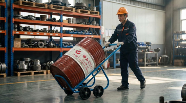
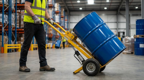
Travel, Lift, And Placement Procedures For Operators
Safe operation began with approaching the load slowly, square to the pallet, with forks level and spaced to support the outer stringers. Operators inserted forks fully under the pallet to maximize support length and avoid point loading on deck boards. They lifted smoothly, then tilted the mast slightly back to seat the load against the backrest and lower it to a travel height of roughly 150–300 mm. This configuration kept the center of gravity low and rearward, improving longitudinal stability.
During travel, operators maintained moderate speeds, avoided sharp turns, and reduced speed further when operating near rated capacity. They planned routes to minimize slopes, rough surfaces, blind corners, and pedestrian conflicts. When placing loads, the forklift stopped close to the target, applied the parking brake when required, and leveled the forks before lowering. Operators set the load down fully, released fork tilt, and reversed straight back until forks cleared the pallet before lowering forks to a safe travel or park position.
Predictive Maintenance And Smart Load Monitoring
Predictive maintenance supported safe pallet handling by preserving rated lifting and braking performance. Regular inspections covered forks, mast channels, chains, hydraulic hoses, and tires, with documented criteria for wear limits and immediate removal from service when exceeded. Hydraulic leaks, abnormal mast noises, or uneven lifting indicated developing faults that could reduce effective capacity or cause uncontrolled movements. Tire condition and pressure directly affected stability, especially when transporting stacked pallets at height.
Smart load monitoring systems used sensors on mast, tilt, and hydraulic circuits to estimate real-time load moment. These systems compared measured load and load center against rated capacity curves and could warn operators or automatically limit lift functions when approaching unsafe conditions. Data logging enabled trend analysis, identifying operators who routinely worked near capacity or equipment showing abnormal stress patterns. Integrated approaches that combined predictive maintenance with electronic load monitoring reduced tip-over incidents and unplanned downtime while keeping pallet stacking operations within engineered safety margins.
Summary Of Best Practices For Forklift Pallet Handling
Forklift pallet handling required a combined focus on rated capacity, engineering calculations, stacking geometry, and maintenance. Operators needed to treat the data plate as the primary capacity reference, then adjust for real load center, attachment mass, and terrain. Engineering-based formulas for load center and load moment helped convert theoretical capacity into a conservative safe working load, especially for oversized pallets or double-stacked units. Applying explicit safety factors of at least 20% further reduced the risk of tip-over, falling loads, or structural damage.
Safe stacking practices relied on sound pallet selection, even weight distribution, and control of stack height relative to racking and sprinkler clearances. Placing the heaviest items low, avoiding overhang, and matching pallet dimensions to rack beams preserved a low, stable center of gravity. OSHA and ANSI requirements mandated that stored materials resist sliding, collapsing, or tipping, and that forklift loads never exceeded the truck’s adjusted capacity. Following structured travel, lift, and placement procedures, with the mast slightly tilted back and the load kept low during motion, minimized dynamic instability.
Predictive maintenance and smart monitoring technologies increasingly shaped future practice. Regular inspection of forks, chains, mast, tires, and hydraulics, backed by oil analysis and scheduled component replacement, reduced unplanned downtime and preserved lifting performance. IoT-based load sensors, inclination monitoring, and auto-derating systems supported operators by warning of overloads or unsafe angles in real time. The industry trend moved toward integrating these digital tools with rigorous operator training and engineering-based planning, providing a balanced evolution where higher productivity aligned with quantifiable safety margins and regulatory compliance.