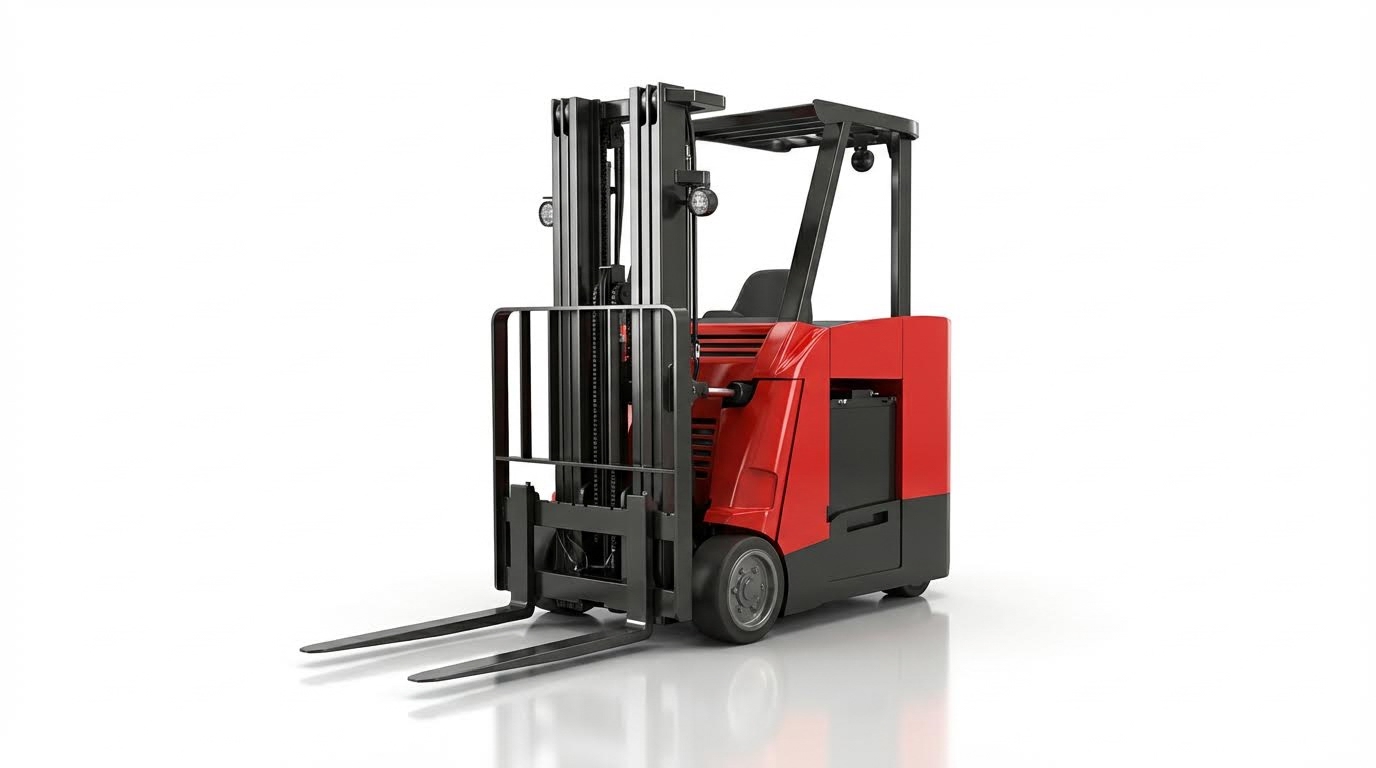
Stand-up forklifts operated in narrow aisles relied on carefully tuned speed settings, stability systems, and hydraulic controls to balance throughput and safety. This article examined how travel, lift, and cornering speeds interacted with regenerative braking, rollback control, and electronic speed limits to shape real-world performance.
It also reviewed modern control architectures, including motor controllers, ECUs, and programmable operator modes, and showed how technicians used diagnostic tools and verification runs to tune parameters. Finally, it connected speed optimization with safety systems, battery health, maintenance planning, and lifecycle cost, providing a structured framework for configuring and operating stand-up trucks in demanding warehouse order picker environments.
Key Speed Parameters In Stand-Up Forklift Operation
Key speed parameters defined how stand-up forklifts balanced throughput, safety, and component life. Travel, hydraulic, cornering, and braking-related settings interacted through the truck’s control system. Correct tuning aligned these parameters with aisle width, rack height, load profile, and operator skill. Poorly configured settings typically reduced productivity, increased near-misses, and accelerated wear.
Travel Speed, Acceleration, And Deceleration
Travel speed parameters limited maximum truck velocity in loaded and unloaded conditions. Typical unloaded stand-up forklifts operated around 12 km/h, with lower limits for loaded travel or sensitive areas. Acceleration curves controlled how quickly current ramped into the drive motor, shaping the response from pedal input to wheel torque. Deceleration settings defined how fast the truck reduced speed when the operator released the accelerator, before any service brake input. Technicians usually adjusted these values through controller parameters such as VMAX, ACCEL_CURVE, and DECEL_RATE, then validated settings with measured test runs.
Hydraulic Lift, Lower, And Tilt Speed Settings
Hydraulic speed settings governed lift, lower, tilt, and attachment functions through the hydraulic pump motor and proportional valves. Control units allowed separate parameters for starting speed, inching speed, maximum speed, and acceleration or deceleration of hydraulic motions. Slower lift and tilt speeds reduced mast sway and improved load stability, especially at high elevations or with fragile goods. Lowering speed required careful calibration to prevent hard landings that damaged pallets or forks. Adjusting hydraulic speeds for applications that did not require maximum performance reduced energy consumption and extended pump, valve, and mast component life.
Cornering, Reach, And Mast-Height Speed Limits
Cornering speed reduction systems automatically decreased travel speed based on steer angle and current speed. This limited lateral forces that could destabilize the truck in tight turns or narrow aisles. Reach interlock functions reduced or locked travel when the reach carriage extended, protecting components and improving stability with off-center loads. Mast-height speed limiting tied travel speed to mast elevation, often cutting speed by up to 50% above the primary stage. Mast lift limit switches with programmable stops prevented contact with low ceilings or overhead services, while bypass modes allowed controlled override for special tasks. These layered limits formed a coordinated stability envelope around the truck’s dynamic behavior.
Regenerative Braking, Plugging, And Rollback Control
Regenerative braking converted kinetic energy into electrical energy when operators released the accelerator, feeding power back into the battery. Parameter settings defined how aggressively the truck decelerated under regen, influencing stopping distance and operator comfort. Plugging described the controlled braking and reversal that occurred when operators commanded opposite travel direction while moving; technicians tuned plugging strength to balance quick directional changes with tire and drivetrain wear. Rollback control limited reverse movement on grades after pedal release, sometimes holding the truck stationary for several seconds before controlled descent. Electro-magnetic parking brakes and anti-roll back functions provided additional ramp hold capability, allowing safe operator exit on slopes without mechanical chocks.
Control Systems And Tuning Methods For Speed
Modern stand-up forklifts used electronic control systems to manage speed, torque, and hydraulic performance with high precision. Engineers tuned these systems through structured parameter sets that governed drive motors, hydraulic pumps, and braking behavior. Correct tuning improved throughput, reduced energy use, and extended component life while maintaining compliance with site safety policies.
Motor Controllers, ECUs, And Drive Parameter Sets
Electric stand-up forklifts relied on AC motor controllers and vehicle control modules to regulate travel speed. These units adjusted motor current and frequency to enforce limits such as maximum travel speed, acceleration curves, and regenerative braking strength. Parameter sets typically included values like Max_Travel_Speed, ACCEL_CURVE, DECEL_RATE, and separate lift and lower speed limits. Technicians configured these via service software, then validated that real-world speeds stayed within specified km/h limits and stopping distances. Proper tuning also coordinated drive and hydraulic demands to avoid voltage sag and maintain stable performance under varying loads.
Operator Modes, PIN Access, And Speed Lockouts
Control systems often supported multiple operator modes to adapt speed to different skill levels and tasks. Typical configurations included Performance, Standard, and Eco modes, each with distinct limits for maximum speed, acceleration, and hydraulic response. Supervisors used PIN-based access control to unlock higher-speed profiles only for trained operators or specific shifts. Speed lockouts integrated with features like Guardian-type stability systems, reach interlocks, and mast-height limits to automatically cap speed when stability margins decreased. This layered approach allowed fleets to standardize safe behavior while still enabling high productivity in suitable zones and applications.
Diagnostic Tools, Testing, And Verification Runs
Technicians used dedicated diagnostic tools to read, adjust, and log speed-related parameters from controllers and ECUs. These tools displayed live data such as travel speed, motor current, battery voltage, and hydraulic pressure during test runs. After a parameter change, standards-compliant practice required verification runs that measured no-load and loaded travel speed, lift and lower rates, and rollback behavior on a grade. Technicians checked that cornering speed reduction, regenerative braking, and over-speed alarms triggered at the intended thresholds. Documented test results supported regulatory compliance, internal safety audits, and consistent performance across the fleet.
Safety, Productivity, And Lifecycle Considerations
Safety, productivity, and asset lifecycle formed an interdependent triangle in stand-up forklift speed optimization. Engineers and fleet managers had to configure speed parameters so that stability limits, operator behavior, and energy usage remained within safe envelopes while still meeting throughput targets. Modern electronic control architectures allowed precise tuning of these envelopes, but incorrect settings increased incident risk, component wear, and battery degradation. A structured approach that linked speed settings to layout, load spectrum, and maintenance feedback delivered the best long-term results.
Stability Systems, OSS, And Over-Speed Management
Advanced stability systems used mast height, tilt angle, steer angle, and travel speed inputs to limit risk of tip-over or load loss. Guardian-type stability logic reduced travel speed when the mast passed the primary stage and also restricted forward tilt by about two degrees, especially with elevated loads. Operator Sensing Systems monitored seat or presence switches and enforced neutral shift, parking brake alarms, and seat belt indication to prevent unsafe dismounting or unrestrained operation. Over-speed alarms and programmable travel speed ceilings ensured operators did not exceed validated limits, especially in congested or mixed-traffic zones. Together, these systems allowed higher baseline productivity while keeping dynamic stability margins within acceptable design criteria.
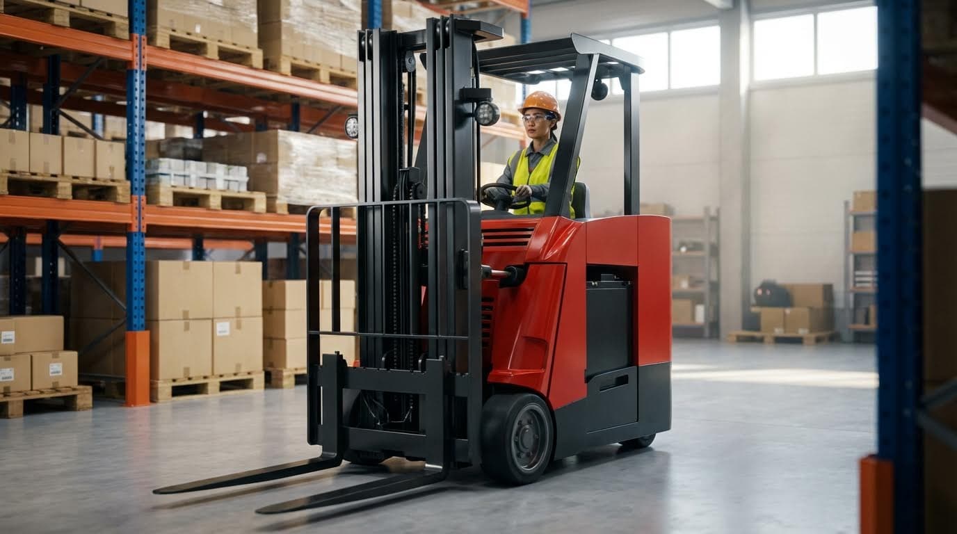
Matching Speed Profiles To Aisle Layout And Loads
Speed profiles needed to align with aisle width, turning radii, and racking geometry. Stand-up forklifts that operated in 8–10 foot aisles benefited from reduced cornering speeds and tighter acceleration curves to maintain control in confined spaces. Reach interlock and mast-height-based speed reductions protected masts, rollers, and rails when the reach mechanism extended or when working near low ceilings or overhead obstructions. Load-dependent speed reduction, using hydraulic pressure or load weight sensing, limited travel speed with heavier pallets to preserve stability and braking performance. Engineers typically validated these profiles through on-site test runs, confirming clearance margins, stopping distances, and maneuvering times for representative load cases.
Energy Efficiency, Battery Health, And Duty Cycles
Speed and acceleration settings directly influenced energy consumption and battery stress across a shift. Higher maximum travel speeds and aggressive acceleration curves increased peak current draw, raising battery temperature and accelerating depth-of-discharge cycles. Regenerative braking and adjustable plugging response allowed recovery of a portion of kinetic energy, but excessive aggressive plugging could increase thermal loading on controllers and motors. Matching speed maps to realistic duty cycles, including average travel distance, stop frequency, and lift pattern, reduced unnecessary current spikes and extended battery life. Lift interrupt levels, linked to state-of-charge, protected batteries by disabling lift at predefined discharge thresholds, aligning truck performance with the installed battery type and capacity.
Maintenance Intervals, Hour Meters, And Auto Power-Off
Planned maintenance hour meters supported lifecycle management by triggering inspections based on true operating hours rather than calendar time. Adjustable maintenance intervals allowed fleet managers to align service frequency with actual duty severity, such as high-cycle narrow-aisle operations or cold-storage environments. Engine auto-off and auto power-off functions reduced idle hours, limiting unnecessary wear on contactors, pumps, and cooling components while also saving energy. These shutdown timers required careful tuning so that trucks powered down during genuine inactivity without disrupting workflows that involved frequent short pauses. Integrating speed-related checks, such as no-load maximum travel speed and lowering speed verification, into preventive maintenance ensured that earlier tuning remained valid over the truck’s service life.
Summary: Balancing Speed, Safety, And Total Cost
Stand-up forklift speed optimization required a structured balance between travel performance, safety systems, and lifecycle cost. Technicians tuned travel, hydraulic, and braking parameters inside motor controllers and ECUs, then validated changes with controlled test runs. Properly configured acceleration curves, cornering speed reduction, and load-based limits increased throughput while keeping trucks stable in narrow aisles and at height.
Safety architectures such as stability systems, operator sensing, anti-roll-back, and over-speed alarms reduced incident risk without eliminating productivity. Regenerative braking, programmable hydraulic speeds, and lift interrupt levels helped align energy use with battery capacity and duty cycle demands, extending component life and runtime between charges. Planned maintenance hour meters and auto power-off features further lowered operating cost by reducing idle consumption and enforcing inspection discipline.
From an implementation perspective, fleets benefited from tiered operator modes, PIN-based speed access, and site-specific profiles matched to aisle width, rack height, and load mass. Future developments continued to move toward more integrated vehicle control modules, finer-granularity parameter maps, and data-driven optimization based on logged operating profiles. The most cost-effective configurations did not simply maximize speed; they calibrated speed envelopes to the real warehouse layout, training level, and maintenance capability, achieving sustainable gains in both safety and total cost of ownership.