Understanding how a straddle stacker actually lifts, carries, and stabilizes a pallet is critical for safe and efficient warehouse design. This guide breaks down how does a straddle stacker lift work from the ground up: leg geometry, mast and fork motion, hydraulic lift circuits, and electric drive and braking. You will also see how capacity, load center, and aisle dimensions tie directly into stability and equipment selection. Use it as an engineering-level overview to match stacker design to your application while protecting operators, product, and infrastructure.
Core Straddle Stacker Design And Working Principles
This section explains the core geometry and kinematics that answer the question “how does a straddle stacker lift work” from a structural point of view. The focus is on how the legs, mast, carriage, and forks define the safe load envelope and motion path so you can match the machine to your pallets, aisles, and racking.
Straddle leg geometry and load envelope
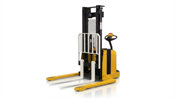
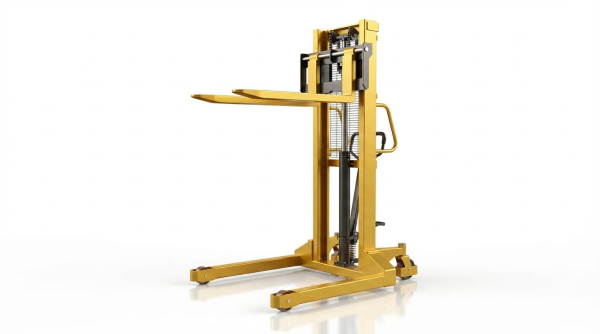
Straddle stacker legs do two main jobs: they carry the truck’s weight and they “straddle” the pallet or load so the mast can sit close to the center of gravity. Their geometry directly sets what you can pick up, how narrow your aisles can be, and how stable the stacker feels under load.
Typical key dimensions that define the leg geometry and load envelope are shown below.
| Parameter | Typical range / value | Why it matters |
|---|---|---|
| Overall leg width (outside–outside) | 1270–1400 mm spec data | Must clear pallet or stillage width while still fitting your aisles. |
| Fork length | ≈1125 mm spec data | Defines usable pallet length and required rack beam depth. |
| Rated load center | ≈600 mm from fork heel spec data | Determines the safe load envelope in front of the mast. |
| Overall length (with forks) | 1650–1750 mm spec data | Impacts turning radius and minimum aisle width. |
| Turning radius | ≈1400 mm spec data | Defines how tightly the stacker can rotate in aisles. |
| Rated capacity | ≈1200 kg class spec data | Combined with load center to set the safe working envelope. |
From a mechanics point of view, the legs form the “base triangle” that resists tipping. When you ask “how does a straddle stacker lift work without tipping,” the answer is: by keeping the combined center of gravity of truck plus load inside this triangle as the mast raises.
To keep the load envelope safe, engineers balance three geometric relationships:
- The leg span must be wider than the pallet or load, but not so wide that aisle width becomes excessive.
- The fork length and rated load center must match typical pallet dimensions so the center of mass stays close to the mast.
- The wheelbase and turning radius must allow the truck to rotate within your aisle width while keeping the legs fully under the rack or load.
Practical selection tips for leg geometry
When selecting a straddle stacker, check: pallet width across the stringers, any overhanging product, minimum aisle width between racks, and whether you need to enter closed pallets or only open-bottom pallets. Then compare these with the published leg width, turning radius, and fork length values on the data sheet. This is the quickest way to avoid interference issues and stability complaints later.
Mast, carriage, and fork kinematics
The mast, carriage, and forks convert hydraulic pressure into controlled vertical motion. This is the core of how a straddle stacker lift works in daily operation: the hydraulic cylinder pushes chains or directly moves the carriage, which slides along the mast rails while the forks carry the load at a defined load center.
Typical mast and lift-related parameters look like this.
| Parameter | Typical range / value | Engineering impact |
|---|---|---|
| Rated lift height | ≈2840–3500 mm spec data | Maximum pallet placement height in racking. |
| Mast height (lowered) | ≈2128–2600 mm spec data | Clearance needed for doors, mezzanines, or low beams. |
| Mast height (extended) | ≈3960–4210 mm spec data | Defines maximum reach into high bay storage. |
| Lift motor rating | ≈3 kW, S3 15% duty spec data | Sets available hydraulic power and typical lift speed. |
| Battery configuration | 2×12 V / 125 Ah to 24 V 50 Ah Li-ion spec data | Limits duty cycle and how often you can lift per shift. |
In most designs, the mast is a welded upright with cold-formed channels. The carriage rides these channels on load rollers, guiding the forks in a nearly vertical path. The hydraulic cylinder either drives the carriage directly or via leaf chains and a pulley arrangement. During design, engineers calculate maximum working pressure, flow rate, and cylinder wall thickness to ensure safe lifting and prevent structural failure using standard hydraulic design methods.
To understand the kinematics in simple terms, follow this sequence when the operator lifts a pallet:
- The operator commands lift; the electric motor drives the hydraulic pump, generating flow and pressure sized for the rated load based on system design.
- Pressurized oil enters the lift cylinder; the piston extends and either raises the carriage directly or tensions the chains over sheaves.
- The carriage slides up the mast rails; the forks, fixed to the carriage, carry the load at the defined 600 mm load center.
- As height increases, the combined center of gravity moves forward and upward, so the leg base and counterweight must still keep it inside the stability polygon.
Why duty cycle and pressure ratings matter
Lift systems are designed around maximum working pressure, target lift speed, and expected duty cycle. Engineers select pump displacement, motor power, and cylinder bore so the system can repeatedly lift rated loads without overheating or overstressing structural parts following standard hydraulic design practice. If you push the stacker beyond this envelope—overloading or running continuous lifts—the mast rollers, chains, and cylinder seals wear out much faster.
When you put the leg geometry and mast kinematics together, you get the complete picture of how a straddle stacker lift works: the legs define the footprint and load envelope on the floor, while the mast and carriage move that load vertically along a constrained path, always trying to keep the center of gravity within the stable base defined by the straddle legs.
Hydraulic Lift System, Powertrain, And Control
This section explains the “muscle and nerves” of the machine so you can answer in detail: how does a counterbalanced stacker lift work, how fast it should move, and what limits its duty cycle. The focus is on how hydraulic components, electric drive, and braking interact to give safe, repeatable lifting in tight warehouse aisles.
Hydraulic pump, cylinders, and pressure ratings
The hydraulic system converts electrical power into linear lifting force at the mast. Design starts from the required load, lift height, and target lift speed, then works backwards to pump size, cylinder bore, and system pressure. That is the engineering core of how does a battery-powered stacker lift work during the vertical lifting phase.
| Component / Parameter | Function in the lift system | Typical engineering considerations |
|---|---|---|
| Hydraulic pump | Supplies oil flow to the lift cylinder(s) to raise the carriage and forks. | Selected for required flow and pressure to meet lift speed and load demands hydraulic pump selection. |
| Electric lift motor | Drives the hydraulic pump. | Power rating checked against maximum pump pressure × flow plus efficiency losses pump and motor power calculations. |
| Lift cylinder(s) | Convert oil pressure into linear force to raise the mast stages or chains. | Bore sized from required lifting force; wall thickness checked against maximum working pressure and buckling cylinder pressure and wall checks. |
| System working pressure | Upper pressure limit for safe operation. | Set during design; used to size hoses, fittings, and structural members, with safety factors against yield maximum working pressure. |
| Relief valve | Protects against overloads and pressure spikes. | Opens slightly above normal working pressure to prevent structural damage to mast and cylinder. |
| Return and suction lines | Feed oil back to tank and from tank to pump. | Sized to keep pressure drop and oil velocity within accepted limits to avoid cavitation and heat. |
In practice, the design workflow for the hydraulic system follows a consistent pattern. Engineers define the load and lift requirements, draft hydraulic schematics, select each component, then verify performance against stability and strength checks hydraulic system design process. This structured approach ensures the stacker lifts smoothly without overstressing the mast or chassis.
Key design checks for cylinders and pressure ratings
When you analyse how does a electric platform stacker lift work at the component level, three checks are critical:
- Bore sizing: Cylinder area × system pressure must exceed the maximum required lifting force with margin.
- Wall thickness: Calculated against hoop stress and buckling for the maximum working pressure wall thickness calculations.
- Stability and structure: Mast, frame, and leg weldments are checked to ensure pressure‑induced loads do not cause permanent deformation stability checks.
Flow control, lift speed, and duty cycles
Flow control hardware determines how quickly the forks move and how repeatable that motion is under different loads. Duty cycle limits protect the pump, motor, and oil from overheating during continuous use. Understanding this part is essential if you want to tune how does a lift stacker lift work for a specific warehouse shift pattern.
| Parameter | Impact on operation | Typical design / usage notes |
|---|---|---|
| Pump flow rate | Directly sets theoretical lift speed for a given cylinder area. | Chosen to balance productivity (higher speed) with control and available motor power flow and pressure selection. |
| Metering / flow control valves | Regulate oil flow during lifting and lowering. | Used to limit maximum lift speed and smooth out load‑dependent speed changes. |
| Check and counterbalance valves | Prevent uncontrolled fork descent on hose failure or valve leakage. | Hold the load in position and give controlled lowering even with varying loads. |
| Rated lift motor duty cycle | Defines how long the lift motor can run in a given period. | Example: 3 kW lift motor at S3 15% duty cycle lift motor duty rating. |
| Thermal limits | Oil and motor temperatures must stay below design thresholds. | High‑frequency lifting cycles require larger oil volumes, cooling paths, or derated speeds. |
| Target lifting speeds | Set productivity expectations. | Large straddle carriers reach up to 12 m/min under load and 20 m/min without load lifting speeds; straddle stackers use lower but same‑order values. |
For warehouse stackers, designers usually cap travel speed around 5 km/h, both laden and unladen, to control stopping distances and operator reaction time typical travel speed. The combination of pump flow, valve sizing, and motor duty cycle defines how many full lift cycles you can safely run per hour without overheating.
- Short, intermittent lifts at low height use only a fraction of the duty cycle and thermal capacity.
- Frequent lifts to maximum height with near‑rated load push the hydraulic system towards its duty limits.
- Designers may derate lift speed or recommend rest intervals for very intensive applications.
Practical tips for matching flow and duty cycle to your application
When specifying a stacker for a real warehouse:
- Estimate average lift height and load per cycle (not just the worst case).
- Calculate approximate lift time from pump flow and cylinder area, then add dwell and travel time.
- Compare the resulting “motor on” time per hour with the lift motor duty class (such as S3 15%).
- If the calculated duty exceeds the rating, choose a higher‑rated motor, reduce lift speed, or accept lower throughput.
Electric drive, batteries, and braking systems
The powertrain answers the second half of how does a manual platform stacker lift work: how it travels, stops, and gets its energy. Modern units use compact AC drive motors, electromagnetic brakes, and battery packs sized for a full shift in typical duty.
| Subsystem | Key spec / feature | Role in operation |
|---|---|---|
| Electric drive motor | Approx. 1.27 kW rating at S2 60 min drive motor rating. | Provides tractive effort for forward and reverse travel. |
| Type of drive unit | AC drive unit AC drive specification. | Gives good torque control, regenerative capability, and reduced maintenance versus DC drives. |
| Travel speed | ≈ 5 km/h laden and unladen travel speed. | Balances productivity with safe stopping distance in narrow aisles. |
| Battery configuration | Typical range: 2 × 12 V / 125 Ah to 24 V / 50 Ah lithium battery voltage and capacity. | Supplies energy for both drive and hydraulic lift circuits over the shift. |
| Service brake | Electromagnetic brake brake type. | Automatically applies when the drive is disabled; provides controlled stopping and parking. |
| Power supply (large straddle systems) | Three‑phase four‑wire, 380–440 V, 50 Hz three‑phase power configuration. | Used as reference for larger straddle carriers; stackers use onboard batteries instead of grid supply. |
In operation, the control system coordinates drive, lift, and braking so the operator can keep forks low during travel and only lift when in position. Electromagnetic brakes engage automatically when the operator releases the travel control or activates the emergency stop, which is a major contributor to safe stopping in tight warehouse layouts electromagnetic service brakes.
- Battery state of charge directly affects how long rated lift and travel speeds can be maintained.
- AC drive technology helps recover some energy during deceleration, extending runtime in stop‑start duty.
- Scheduled maintenance should include checks on hydraulic pressure systems, braking response, and control electronics to prevent failures during peak usage scheduled maintenance practices.
How drive and lift systems interact in real use
From an engineering point of view, how does a electric platform stacker lift work during a full cycle looks like this:
- The operator travels at low speed (around 5 km/h) with forks 100–150 mm above the floor recommended fork height.
- Once aligned, travel is stopped and the brake holds position.
- The lift motor drives the pump, pressurising the cylinder and raising the load at a speed limited by flow‑control valves.
- At target height, valves close and the cylinder holds pressure; the structure carries the load.
- For lowering, valves meter oil back to tank, giving a controlled descent regardless of load within the rated capacity.
This closed loop between electric drive, hydraulics, and control logic is what turns raw motor power and oil pressure into safe, predictable material handling.
Capacity, Stability, And Equipment Selection
Load center, leg width, and aisle constraints
Capacity and stability on a counterbalanced stacker are mainly controlled by three geometry variables: load center, leg width, and aisle width. Understanding these is essential if you want to answer “how does a straddle stacker lift work” in real warehouses, not just in theory.
| Parameter | Typical value / range | Why it matters for capacity & stability |
|---|---|---|
| Rated capacity | ≈ 1200 kg to 2000 kg typical spec range | Maximum safe load at the rated load center and lift height. |
| Standard load center | ≈ 600 mm from fork heel common rating point | Defines overturning moment; longer load = higher moment = lower usable capacity. |
| Overall leg width (outside) | ≈ 1270–1400 mm typical range | Sets the “straddle” footprint and lateral stability; must clear pallet or load. |
| Overall length | ≈ 1650–1750 mm typical range | Influences turning radius and minimum aisle width. |
| Turning radius | ≈ 1400 mm typical spec | Key input for aisle design and rack layout. |
In simple terms, the hydraulic system creates vertical force, but geometry decides whether the truck tips or stays stable. For a given capacity, if you increase the load center (longer pallets, offset loads) you consume the stability margin that the wide straddle legs provide.
Practical rules for matching load and geometry
Use these quick engineering checks when selecting or operating a straddle stacker:
- Keep the load CG as close as possible to the fork heel; avoid overhanging loads beyond the rated 600 mm load center.
- Ensure the pallet or stillage fits fully between the straddle legs; never ride a pallet on top of the legs.
- De-rate capacity whenever using non-standard pallets or long loads; manufacturers typically base ratings on standard pallets at 600 mm load center.
- Confirm aisle width is at least the turning radius plus a safety margin for operator clearance and pallet overhang.
- Remember that the published capacity is valid only on level, firm floors with the mast vertical.
From a “how does a straddle stacker lift work” perspective, the straddle legs act as a wide base triangle resisting the overturning moment created by the hydraulic lift of an elevated load. If aisle width forces you to choose a narrower leg span, you trade away some lateral stability and may need to step down in working height or capacity.
Lift height, mast type, and application fit
Lift height and mast design determine how high you can store product and how the machine behaves dynamically when the load is raised. These factors also feed directly into capacity de‑rating curves, which are central to how does a straddle stacker lift work safely at different rack levels.
| Mast / height parameter | Typical value / range | Selection impact |
|---|---|---|
| Rated lift height | ≈ 2840–3500 mm common range | Sets maximum storage level you can service. |
| Mast height (lowered) | ≈ 2128–2600 mm typical range | Must clear doorways, mezzanines, and low beams. |
| Mast height (extended) | ≈ 3960–4210 mm typical range | Defines required clear height under sprinklers and roof structures. |
As the mast extends, the combined center of gravity of truck plus load moves upward and slightly forward. The hydraulic system can still lift, but the stability triangle shrinks, so the allowable load often reduces at higher lift heights.
- Single-stage masts are simpler and stiffer but have higher lowered height for a given lift height.
- Two- or three-stage masts reduce lowered height for the same lift but add more moving sections and deflection.
- Higher masts require tighter control of floor flatness and racking clearances to avoid contact when the mast flexes.
Quick selection checklist for mast and height
Before finalizing a straddle stacker, verify:
- Highest pallet top height (rack beam + pallet + load) you must reach.
- Required under‑beam clearance above the top storage level.
- Building clear height at the worst location, including sprinklers and ductwork.
- Door and tunnel heights versus mast height (lowered).
- Any future plan to add extra racking levels that would need more lift height.
When you combine capacity, load center, leg width, and mast height, you get the real operating envelope of the machine. That envelope, more than the nameplate rating, defines how does a straddle stacker lift work in your specific warehouse and what safety margin you truly have at each rack level.
Final Engineering Considerations And Best Practices
Engineering a safe straddle stacker application means treating geometry, hydraulics, and powertrain as one linked system. Leg width, fork length, and load center define the stability triangle on the floor. Mast height, carriage design, and lift kinematics decide how the center of gravity moves as the load rises. Hydraulic components, duty cycle, and flow control then govern how smoothly and repeatably that motion happens over a shift.
If any part is mismatched to your pallets, aisles, or racking, the risk shows up as near‑misses, early wear, or tip‑over potential. Oversized loads at long load centers eat into stability margin even when the hydraulic system can still lift. High lift heights on uneven floors amplify mast deflection and operator error. Undersized motors or poor cooling quietly reduce available throughput long before failure.
Operations and engineering teams should therefore start with the real warehouse: pallet sizes, load weights, rack elevations, aisle widths, and duty profile. Then select a stacker, such as an Atomoving unit, whose leg geometry, mast type, hydraulic ratings, and battery capacity match that envelope with clear reserve. Finally, lock in safe procedures: forks low during travel, no overloads, strict respect for rated load center and height, and scheduled maintenance on hydraulics, brakes, and controls.
Frequently Asked Questions
How does a straddle stacker lift work?
A straddle stacker lifts loads using a hydraulic system powered by either manual or electric mechanisms. The forks, located under the load, are raised and lowered to lift pallets or other materials. Straddle Stacker Safety Tips.
What should you do before using a straddle stacker?
Before operating a straddle stacker, perform pre-operation checks. Inspect for damages, verify fluid levels, and ensure all safety features are functional. This helps prevent accidents and ensures smooth operation. Safety Guidelines.
Are straddle stackers designed for small tight spaces?
Yes, straddle stackers are compact and ideal for tight spaces. They offer more versatility than standard forklifts, making them perfect for warehouses with limited space. Compact Straddle Stackers.