Understanding how a pallet jack lifts requires looking at both its hydraulic circuit and its mechanical structure. This article explains the core components that carry the load, how the pump, pistons, and valves convert operator input into vertical fork motion, and which design parameters govern capacity and durability. It also covers maintenance practices, typical hydraulic faults, and emerging digital technologies that enhance monitoring and safety. The goal is to give engineers and operators a clear, system-level view of hydraulic pallet truck lift design for safe, efficient material handling.
Core Components Of A Pallet Jack Lift System
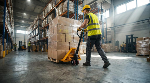
Understanding how a pallet jack lifts starts with its core mechanical and hydraulic components. Each element in the structure, wheel set, control handle, and hydraulic circuit defines how forces travel from the floor to the load. Correct design of these subsystems improves stability, reduces rolling resistance, and protects the hydraulic unit. This section breaks down the physical load path and the interfaces between operator input, wheels, and the hydraulic lift circuit.
Forks, chassis, and load path fundamentals
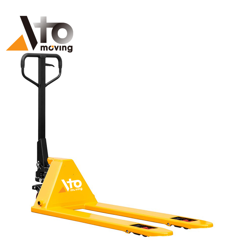
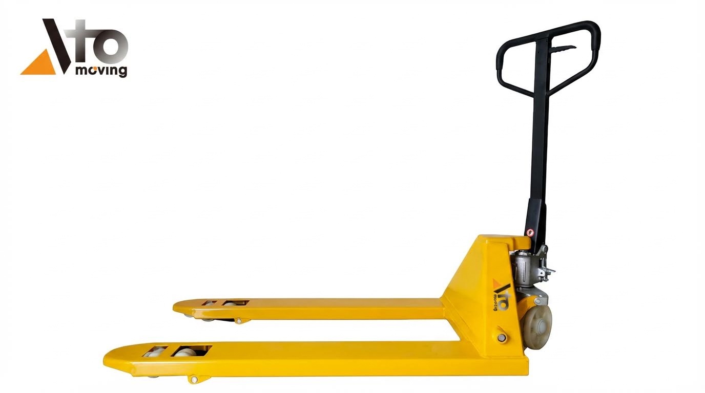
The forks form the primary load-carrying members in a pallet jack lift system. Designers taper the fork tips and keep the fork thickness low to ease entry under standard pallets while limiting floor gouging. The chassis ties the forks to the hydraulic unit and provides a rigid path for vertical and horizontal forces. When a load rests on the forks, forces transfer through the fork sections into the chassis, then into the steering and load wheels, and finally into the floor. To keep stresses within limits, engineers specify structural steels with adequate yield strength and design the fork cross section for the rated capacity, typically 1,000–2,500 kg in industrial models. Proper fork spacing matches pallet openings so the load center aligns with the hydraulic lift point and minimizes bending moments.
Steering, load wheels, and ground contact
Steering and load wheels define how a low profile pallet jack lifts and moves without overloading the operator. The load wheels at the fork tips carry most of the vertical load once the forks raise the pallet a few centimeters. These wheels usually use polyurethane or nylon treads to balance low rolling resistance, noise, and floor protection. The steering wheels under the tiller end support the remaining load and provide directional control through a kingpin and bearing assembly. Ground contact geometry, including wheel diameter and axle spacing, affects required push force, ramp performance, and the risk of ground strikes at dock plates or thresholds. Proper wheel material selection also influences how smoothly the hydraulic lift action feels, because high-friction wheels can amplify jerk when the load starts moving.
Pump handle, linkages, and operator input
The pump handle converts human input into hydraulic energy, which explains a key part of how a pallet jack lifts a heavy pallet with modest effort. When the operator pumps the handle, a mechanical linkage drives the small-displacement hydraulic pump. Designers choose lever arm lengths to keep handle forces within ergonomic limits while still achieving the pressure needed for loads up to roughly 2,500 kg. The handle assembly also integrates the lowering trigger or lever, which actuates a valve in the hydraulic circuit to release pressure in a controlled way. Linkages between the handle, pump piston, and control valve must minimize backlash and wear, because excessive play creates a spongy feel and reduces lifting precision. Bushings and pivot pins require periodic lubrication to keep input forces predictable and to avoid side loads on the pump shaft.
Hydraulic circuit layout and key elements
The hydraulic circuit is the core subsystem that explains how a pallet jack lifts using fluid power instead of direct mechanical jacking. A positive displacement pump draws hydraulic oil from a small reservoir and forces it into the main lift cylinder when the operator strokes the handle. Check valves ensure one-way flow into the cylinder and prevent backflow when the handle returns. As pressure builds, the piston in the lift cylinder extends and drives a linkage that raises the forks relative to the chassis. A separate lowering valve connects the cylinder back to the reservoir when actuated, allowing oil to return and the piston to retract under load weight. Designers often integrate a pressure relief valve to cap system pressure and protect the structure if the operator attempts to lift above the rated capacity. Compact packaging of pump, reservoir, valves, and cylinder inside the jack frame protects components from impact while keeping hose lengths short and minimizing leakage points.
Hydraulic Operation: From Pump Stroke To Fork Lift
Hydraulic operation explains how a pallet jack lifts a load using pressurized fluid and compact mechanical linkages. The system converts short pump strokes from the operator into high-pressure oil flow, which extends a piston and raises the forks. Understanding this sequence helps engineers optimize lift performance, diagnose faults, and design safer material handling systems.
Positive displacement pump and fluid flow
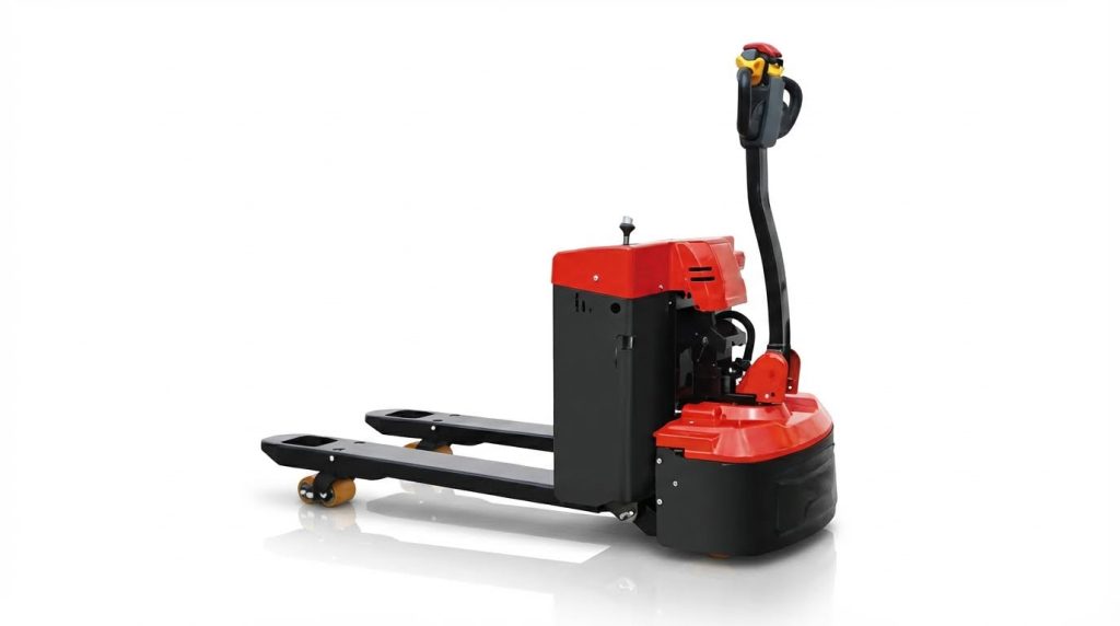
The hydraulic pallet truck uses a small positive displacement pump driven by the handle or a foot pedal. Each stroke moves a fixed volume of hydraulic oil from the reservoir into the pressure chamber. Because the pump is positive displacement, the flow rate depends on stroke frequency, not outlet pressure, up to the relief setting. This characteristic allows the system to build pressures high enough to lift loads between 900 kg and 2 500 kg in typical warehouse units. Internal clearances in the pump stay tight to limit leakage and maintain volumetric efficiency. Engineers select viscosity grades such as ISO VG 32 to balance low-temperature flow with wear protection. Smooth internal passages and short lines reduce pressure drop and energy loss during each pump cycle.
Piston motion, pressure, and load balancing
Pressurized oil enters the lift cylinder and acts on the piston area to generate an upward force. The relationship follows F = p × A, so doubling pressure or piston area doubles available lift force. Designers size the piston diameter so that operator input forces at the handle remain ergonomic while still lifting rated loads. As the piston extends, it pushes a linkage or directly raises the fork frame, converting linear motion into fork elevation. The load distributes through both forks, so uneven pallet loading can create asymmetric bending and side loads on the piston rod. Pressure rises until it balances the combined weight of the load, forks, and moving structure, at which point the forks stop accelerating and move steadily. When the operator stops pumping, trapped oil holds the piston position and keeps the load suspended.
Check valves, relief valves, and safety limits
The hydraulic circuit relies on check valves to control one-way flow and maintain lift pressure between pump strokes. An inlet check admits oil from the reservoir into the pump chamber during handle return. An outlet check opens only when pump pressure exceeds cylinder pressure, then closes to prevent backflow when the handle resets. A pressure relief valve limits maximum system pressure to protect the cylinder, pump body, and chassis from overload. When the operator tries to lift a load above the rated capacity, the relief valve opens and diverts oil back to the reservoir instead of raising pressure further. This behavior explains how a low profile pallet jack lifts safely without catastrophic failure under misuse. Proper relief valve calibration is critical; incorrect settings either reduce available capacity or risk structural damage and seal blowout.
Lift, hold, and lower control valve positions
A multi-position control valve determines whether the pallet jack lifts, holds, or lowers the forks. In the lift position, the valve connects the pump outlet to the cylinder while isolating the return path, so each handle stroke adds oil volume under the piston. In the neutral or hold position, all ports to the cylinder close, trapping oil and locking the piston at a fixed height. High-quality seals around the spool and piston minimize internal leakage, which could otherwise cause slow, unintended fork descent under load. In the lower position, the valve opens a metered path from the cylinder back to the reservoir. Flow restriction in this path controls descent speed so the load lowers smoothly, even when near maximum capacity. Operators modulate the handle or trigger to fine-tune lowering rate, which improves placement accuracy and reduces impact loads on floors and pallets.
Design, Performance, And Maintenance Considerations
Understanding how a pallet jack lifts requires linking hydraulic design to real-world performance and maintenance. This section explains how load ratings, wheel and wear materials, hydraulic reliability, and emerging technologies influence safe, efficient lifting in industrial environments.
Load ratings, fork height, and duty cycles
Engineers define load rating based on how a pallet jack lifts a specified mass at a given load center. Typical manual units rated between 2 000 kg and 3 000 kg relied on a compact hydraulic circuit and high-strength steel forks. The rating assumed the load center near the fork heel, with evenly distributed weight across both forks. Maximum fork height usually reached about 200 mm, which limited lifting to ground-level transport and low staging, not racking. Designers matched hydraulic piston area, pump displacement, and handle leverage so operators could raise rated loads without excessive input force. Duty cycle considerations included number of lifts per hour, travel distance, and average load mass. High-duty applications required thicker fork sections, reinforced chassis welds, and hydraulic components validated through fatigue testing to prevent creep, leakage, or permanent fork deflection.
Material choices for wheels and wear parts
Wheel and wear material selection directly affected how a pallet jack lifts and rolls under load. Nylon wheels offered low rolling resistance and high compressive strength on smooth, hard floors but transmitted more noise and vibration. Polyurethane treads provided quieter operation, better floor protection, and higher traction, useful on coated concrete or slightly uneven industrial floors. Rubber wheels improved grip on rougher or slightly damp surfaces but deformed more under heavy point loads, which increased rolling resistance. Engineers specified hardened steel or ductile iron for core wheel hubs and axles to resist brinelling and shear under repeated impacts. Bushings and pivot pins used hardened steel with surface treatments or polymer bushings to minimize wear without frequent lubrication. Correct material pairing reduced starting force, minimized flat-spotting under static loads, and maintained accurate tracking, which in turn reduced side loads on the hydraulic assembly and extended service life.
Common hydraulic faults and troubleshooting
Typical hydraulic issues affected how a hydraulic pallet truck lifts, holds, and lowers loads. Insufficient or contaminated oil often caused forks to stop short of full height or lift intermittently. Technicians checked oil level first, then inspected for milky appearance or metallic particles indicating water ingress or wear. Trapped air in the circuit, frequently introduced during transport or after inversion, prevented stable pressure build-up; cycling the handle through full up and down strokes while the release valve stayed open helped purge air. If the jack failed to lift rated loads despite correct oil level, misadjusted relief valves or worn pump seals could bypass flow; pressure testing at the pump outlet confirmed this. Failure to lower smoothly pointed to bent piston rods, damaged valve spools, or debris blocking the lowering passage. Visible external leaks at shaft seals, fittings, or cracked housings required immediate repair, because even slow leakage reduced effective pressure and compromised load holding.
Preventive maintenance and oil management
Planned maintenance strongly influenced long-term lifting performance and safety. Daily checks included visual inspection of forks, chassis welds, and wheels, plus confirmation that the hydraulic unit lifted and lowered smoothly under a test load. Monthly tasks typically covered lubricating pivot points, steering linkages, and wheel bearings, as well as checking hydraulic oil level and condition. Operators lowered forks fully after use to reduce seal stress and eliminate trip hazards. Oil management followed hydraulic best practice: using the specified viscosity grade, usually ISO VG 32 for indoor temperatures, and keeping the system clean during top-up with filtered funnels and clean containers. When oil appeared dark, milky, or contaminated with particles, technicians drained it into a clean container, flushed the system with compatible fluid, and replaced strainers or filters where fitted. Documented maintenance intervals, combined with torque-checked fasteners and periodic safety inspections, reduced unexpected failures and maintained consistent lift capacity.
Emerging tech: sensors, AI, and digital twins
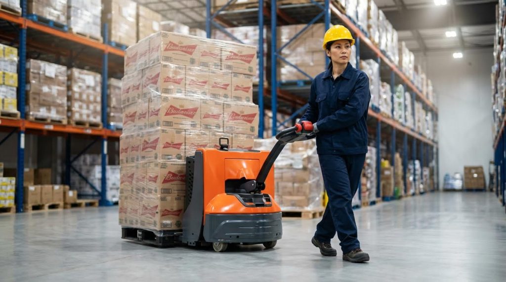
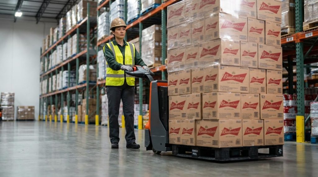
Digital technologies started to reshape how engineers optimized how a walkie pallet truck lifts over its lifecycle. Embedded load cells and pressure sensors allowed real-time monitoring of fork load and hydraulic pressure, which prevented overloads and captured duty-cycle data. Accelerometers and wheel-rotation sensors supported usage analytics, tracking travel distance, impact events, and lift counts per shift. AI algorithms processed this data to predict seal wear, pump degradation, and wheel replacement intervals before failures occurred. Digital twin models represented the pallet jack’s hydraulic and structural behavior in software, enabling simulation of different load spectra, floor conditions, and maintenance strategies. These tools helped engineers refine cylinder sizing, valve characteristics, and frame geometry while validating safety margins against standards. In high-volume fleets, connected systems integrated with warehouse management platforms to assign equipment based on remaining useful life and recent fault codes, improving uptime and reducing total cost of ownership without changing the fundamental hydraulic lifting principle.
Summary: Safe, Efficient Pallet Jack Lift Design And Use
Understanding how a pallet jack lifts helped engineers and operators align design, maintenance, and safety practices. The hydraulic circuit, mechanical linkages, and wheel geometry worked together to convert modest handle input into controlled fork elevation. When users understood this interaction, they could diagnose faults faster and avoid overload or misuse that damaged components and increased risk.
From a technical standpoint, safe use depended on matching rated load, fork height, and duty cycle to the application. Typical manual pallet jack units lifted up to about 2,500 kg to roughly 200 mm, which suited low‑level transfer rather than high stacking. Correctly specified wheels, clean hydraulic oil, and intact seals kept the system efficient and reduced unplanned downtime. Regular inspections for leaks, bent forks, and abnormal noises, combined with scheduled lubrication and oil checks, extended service life and preserved lift performance.
Future pallet jack designs increasingly integrated sensors, condition monitoring, and digital twins to track how a pallet jack lifts in real time. These tools supported predictive maintenance, optimized fleet utilization, and documented overload events or shock impacts. However, even with advanced electronics, fundamental hydraulic principles and mechanical constraints still governed safe operation. Facilities that combined sound engineering design, data‑driven monitoring, and disciplined operator training achieved the best balance of safety, efficiency, and total lifecycle cost. For instance, integrating solutions like a high lift pallet truck with infrared sensor or leveraging advanced tools such as a forklift drum grabber could further enhance operational precision and safety.