Pallet jack hydraulics converted simple handle motions into reliable vertical lifting in warehouses, factories, and distribution centers. This article explains how the core components of a pallet jack lift system worked together, from the pump handle and linkage to the cylinder, forks, and safety valves. It then examines the hydraulic lifting principle, mechanical force transmission, and how design variants such as low-profile, heavy-duty, and electric units addressed different applications. Finally, it reviews reliability, maintenance, and failure modes, and closes with key design tradeoffs and future trends in pallet jack lifting mechanisms.
Core Components Of A Pallet Jack Lift System
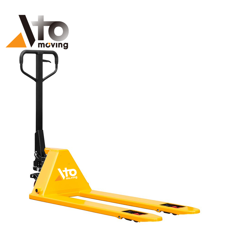
A pallet jack lift system used a compact set of mechanical and hydraulic elements to convert operator input into controlled vertical motion. Designers integrated the handle, linkage, hydraulic group, and fork structure to balance capacity, cost, and maneuverability in confined industrial spaces.
Pump Handle, Linkage, And Control Positions
The pump handle provided the primary human–machine interface for traction, steering, and lifting. Operators moved the handle up and down to drive the pump piston through a pinned linkage, which translated angular motion into near-linear pump strokes. The same handle usually incorporated three control positions: lift, neutral, and lower, selected via a trigger or small lever. In lift mode, the release valve stayed closed, so each stroke increased hydraulic pressure; in lower mode, the valve opened and vented pressure to return the forks to the floor. Neutral isolated the hydraulic circuit while allowing the operator to steer and tow the unit without unintended fork movement.
Hydraulic Pump, Cylinder, And Reservoir
The hydraulic group consisted of a small displacement pump, an integrated reservoir, and a single-acting cylinder. Pump strokes forced hydraulic oil from the reservoir through inlet and outlet check valves into the cylinder bore, raising system pressure according to Pascal’s law. As pressure increased, the cylinder piston extended and transmitted force into the fork lifting linkage, elevating the load. The reservoir volume ensured adequate oil supply over the full stroke range and compensated for internal leakage and thermal expansion. Designers specified hydraulic jack oil with appropriate viscosity and anti-wear additives to maintain performance over a broad temperature range and reduce cavitation and wear.
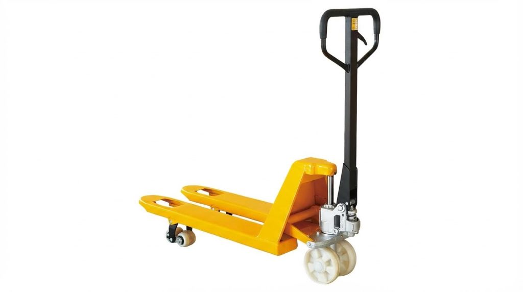
Fork Assembly, Load Wheels, And Pivot Points
The fork assembly formed the primary load-bearing structure and interface with standardized pallets. Two parallel fork blades supported the pallet deck, while load wheels at the fork tips rolled within pallet entry openings. A series of pivot points and link arms connected the cylinder output to the fork frames, creating a compact scissor-like lifting motion. As the cylinder extended, the linkage rotated about chassis pivots and pushed the forks upward by approximately 80–120 mm, sufficient to clear warehouse floors and dock thresholds. Steering wheels at the tiller end carried a significant portion of the static and dynamic load, so their placement and bearing selection influenced rolling resistance, turning radius, and floor impact.
Overload Protection And Check Valves
Overload protection relied on a calibrated safety valve integrated into the hydraulic block. When system pressure exceeded the design limit corresponding to rated capacity, this valve opened and bypassed oil back to the reservoir, preventing further lifting and protecting the frame and cylinder from overstress. Check valves controlled one-way flow into and out of the cylinder, maintaining fork height under static load by preventing reverse flow when the pump was idle. A separate lowering valve, actuated by the handle control, intentionally released pressure in a metered fashion for smooth descent. Correct sizing and cleanliness of these valves were critical, since leakage led to creeping fork drop, while contamination caused sticking, pressure spikes, or failure to lift to full height.
Hydraulic Lifting Principle And Force Transmission

The hydraulic lifting principle in pallet jacks relied on fluid pressure to convert small manual forces into significant lifting forces. Designers used compact hydraulic circuits to keep the mechanism simple, robust, and inexpensive while still meeting industrial duty cycles. Force transmission paths combined mechanical linkage at the handle with hydraulic pressure in the pump and cylinder, then translated cylinder stroke into fork vertical travel. Understanding this chain of energy conversion allowed engineers to size components correctly and operators to use the equipment within safe limits.
Converting Handle Motion Into Hydraulic Pressure
The operator pumped the handle to drive a mechanical linkage connected to a small displacement hydraulic pump. Each handle stroke moved a pump plunger, forcing hydraulic oil from the reservoir through a check valve into the pressure chamber. With the release valve closed, oil could not return to the reservoir, so pressure built in the cylinder circuit according to Pascal’s law. The system converted relatively long, low-force handle motion into short, high-pressure fluid displacement. Correct valve timing and sealing were critical to prevent backflow and pressure loss during each stroke.
Cylinder Extension And Fork Vertical Travel
Rising hydraulic pressure acted on the piston area inside the lift cylinder, generating an upward force equal to pressure multiplied by piston area. As the piston extended, it pushed a yoke or linkage that transferred motion to the fork assembly or a lifting platform. Fork vertical travel was usually greater than cylinder stroke due to additional mechanical leverage in the linkage geometry. When the operator actuated the lowering valve, fluid flowed back to the reservoir, pressure dropped, and the piston retracted under the combined effect of load weight and gravity. Controlled orifice sizing in the lowering circuit ensured smooth descent without sudden drops.
Mechanical Advantage, Stroke, And Load Capacity
Engineers selected handle length, pump plunger diameter, and cylinder bore to balance operator effort, stroke count, and rated capacity. A longer handle and smaller pump plunger reduced required input force but increased the number of strokes to reach full lift height. Larger cylinder bores increased lifting force for a given pressure but demanded stronger frames and higher quality seals. Typical hand pallet jacks operated below the setting of an internal overload valve, which limited maximum system pressure to protect the structure. Load capacity, lift height, and stroke length formed a coupled design space that manufacturers optimized for warehouse use, short travel, and frequent cycling.
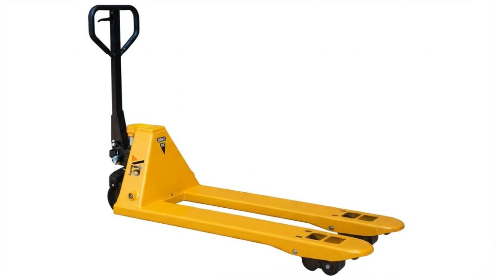
Low-Profile, Heavy-Duty, And Electric Variants
Low-profile pallet jacks used reduced fork and cylinder stack heights to enter thinner pallets, which constrained cylinder diameter and linkage geometry. To maintain adequate capacity, designers sometimes increased hydraulic pressure ratings or used higher strength steels in the fork structure. Heavy-duty models incorporated larger cylinders, thicker fork sections, and reinforced pivot points to handle higher rated loads without excessive deflection. Electric pallet jacks retained the same hydraulic lifting principle but replaced manual pumping with a motor-driven pump, stabilizing lift speed and reducing operator fatigue. Across all variants, the fundamental force transmission chain remained constant: mechanical input to hydraulic pressure, then cylinder force to fork motion.
Reliability, Maintenance, And Failure Modes
Common Hydraulic Issues And Root Causes
Pallet jack hydraulic systems historically failed for predictable, diagnosable reasons. Slow or incomplete lifting often indicated low oil level, air entrainment, or a partially open release valve. Creeping down under load pointed to internal leakage past the piston seal, check balls, or the lowering valve seat. External oil around the pump body, cylinder, or connections revealed worn seals, damaged rods, or cracked housings.
Contamination played a dominant role in long-term reliability loss. Dirt or metal particles scored piston rods and valve seats, preventing proper sealing and causing pressure loss. Water ingress degraded hydraulic oil, reduced lubricity, and promoted internal corrosion. Excessive side loading or overload operation bent forks or linkages, misaligned the pump geometry, and accelerated seal wear. Lack of periodic inspection allowed minor leakage or sluggish response to progress into full hydraulic failure.
Bleeding Air, Refilling Oil, And Seal Repair
Restoring performance required systematic hydraulic service. Technicians first verified the release valve position, then checked reservoir oil level using the manufacturer’s reference mark. They always used hydraulic jack oil with appropriate viscosity characteristics, avoiding brake fluid or generic hydraulic oils that affected seals and cold-weather performance. After refilling, they bled air from the system to remove compressible pockets that reduced lift height and speed.
Bleeding typically involved pumping the unloaded jack through full strokes with the lowering valve briefly cracked, or using a dedicated bleeder screw when provided. Persistent spongy behavior or rapid creep indicated internal leakage, demanding seal and valve service. Repair kits usually included piston cups, O-rings, check balls, and springs, which technicians installed after complete disassembly and cleaning of the pump and cylinder. They inspected rods for scoring and replaced any severely damaged components to avoid rapid recurrence of leaks.
Lubrication, Contamination Control, And Inspection
Preventive maintenance focused on friction control and cleanliness. Operators lubricated pivot joints, linkages, and wheel bearings with suitable oils or greases to reduce wear and handle effort. They kept the piston rod and pump area clean, wiping away dust and oil film that trapped abrasive particles. Periodic deep cleaning removed hidden grime from under the forks and around the pump base, limiting contamination ingress into seals and valves.
Inspection routines checked for cracked forks, bent arms, loose fasteners, and flat-spotted or damaged wheels. Technicians looked for oil traces on the floor, around the cylinder base, and near the handle-mounted valve, which signaled early leakage. They verified smooth handle stroke, consistent lift per pump, and stable fork height under a test load. Facilities that enforced clean, dry storage reduced corrosion, seal hardening, and contamination from moisture or aggressive vapors, thereby extending hydraulic service life.
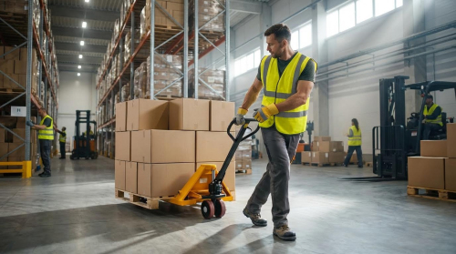
Safety, Standards, And Operator Load Limits
Reliability and safety were tightly linked through adherence to rated capacities and standards. Operators kept loads within the nameplate rating and respected the specified load center, avoiding off-center or top-heavy pallets that increased structural and hydraulic stress. They transported loads with forks lowered as much as practical and maintained clear travel paths to prevent impact damage. On slopes, they controlled speed and orientation to avoid runaway loads or sudden side loading on the hydraulic unit.
Standards for industrial trucks defined design safety factors, labeling, and testing methods, guiding manufacturers on overload protection and stability requirements. Many pallet jacks incorporated overload valves that limited maximum hydraulic pressure, preventing lifting of excessive loads. Routine operator training emphasized correct pumping technique, gradual lowering using the control lever, and pre-use checks for leaks or mechanical defects. Facilities that combined standards-based equipment selection with disciplined inspection and operator practices achieved higher reliability and reduced hydraulic failure incidents.
Summary: Design Choices, Tradeoffs, And Future Trends
Pallet jack lifting systems relied on compact hydraulic circuits, short-stroke cylinders, and simple mechanical linkages. Designers balanced lift capacity, fork height range, and chassis size against cost and operator effort. The core tradeoff lay between mechanical simplicity and performance: manual systems minimized components but increased physical demand and cycle time. Electric and heavy-duty variants improved throughput and ergonomics but added weight, cost, and maintenance complexity.
Industry practice favored standardized pump units, modular fork frames, and proven safety elements such as overload valves and check valves. These choices reduced manufacturing cost and simplified field repair, but limited custom optimization for niche applications. Reliability depended strongly on contamination control, correct hydraulic oil, and regular inspection of seals, rods, and wheels. Poor maintenance increased risks of creeping-down failures, sluggish lift, and structural damage to forks under repeated overload.
Future trends pointed toward incremental electrification, better ergonomics, and smarter condition monitoring. Battery-powered walkies already reduced operator strain and supported higher duty cycles in warehouses and distribution centers. Sensor-based health monitoring, integrated overload indication, and quick-connect hydraulic modules were likely to shorten downtime and support predictive maintenance. At the same time, regulatory pressure on manual handling and safety would continue to drive clearer load labeling, stability guidance, and design margins.
For practitioners, selecting a lift system required matching rated capacity, fork geometry, and hydraulic architecture to pallet types, aisle widths, and duty cycles. Manual jacks remained appropriate for low-intensity, short-distance moves with moderate loads. Heavy-duty, low-profile, stainless, or electric variants suited higher loads, hygiene-sensitive areas, or multi-shift operation. The technology evolved conservatively, but continuous refinement in seals, surface finishes, and hydraulic control improved safety, durability, and lifecycle cost without abandoning the fundamental hydraulic jack principle.