Pallet jack lifting capacity governed design choices, safety margins, and daily operating practices across material handling facilities. This article examined how capacity and load ratings were defined, how real-world usable capacity differed, and how geometry such as load center and fork length drove derating. It then analyzed the engineering factors that limited capacity, including hydraulic pressure, fork steel design, wheel contact stresses, and specialized low‑profile or heavy‑duty configurations. Finally, it linked these engineering limits to field practice, covering nameplate interpretation, safe loading, inspection criteria, and modern predictive maintenance and digital twin approaches for sustaining safe capacity over the equipment life cycle.
Defining Pallet Jack Capacity And Load Ratings
Pallet jack capacity definitions established the safe working envelope for short-range material handling. Engineers specified these ratings from structural strength, hydraulic limits, and stability criteria rather than marketing targets. Operators needed to understand how rated capacity, load center, and fork geometry interacted to avoid overloading and tipping. Clear interpretation of labels and datasheets linked design assumptions to real warehouse conditions.
Rated Capacity Vs. Real-World Usable Capacity
Rated capacity described the maximum load a pallet jack safely carried under standardized test conditions. Manufacturers determined this value using specified load centers, fork heights, and level, firm floors. In practice, usable capacity often reduced due to off-center loads, uneven floors, and dynamic effects such as braking or turning. Training programs and OSHA-aligned guidance emphasized staying below the nameplate rating when conditions deviated from the test assumptions. Hydraulic leakage, fork damage, or worn wheels further reduced effective capacity even if the label value remained unchanged. Engineers and safety managers therefore treated the rated capacity as a hard upper limit, not a target operating point.
Typical Capacity Ranges By Pallet Jack Type
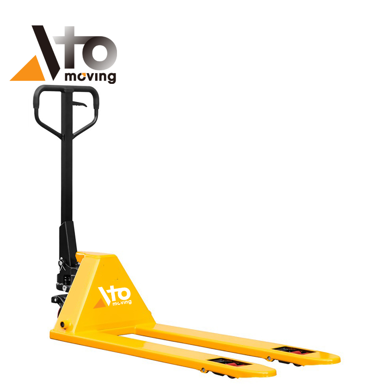
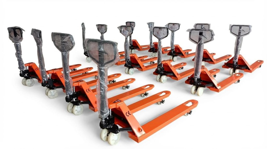
Manual hydraulic pallet jacks typically handled 2000 kg to 5000 kg according to industrial catalogues such as ONEN’s CBY-AC series. Low-profile and ultra-low-profile models from manufacturers like CUBLIFT covered roughly 1000 kg to 3500 kg as standard, with heavy-duty variants and custom builds reaching up to about 5500 kg. Rider and electric end-controlled pallet jacks, such as Toyota’s models, operated in a similar mass range but expressed capacities in pounds, for example 6000 lb and 8000 lb on level floors. Engineers selected capacity bands based on palletized load mass, duty cycle, and aisle conditions rather than simply choosing the highest rating. Higher-capacity trucks introduced greater wheel contact stresses and required better floor quality and more skilled operators. Matching capacity class to the heaviest realistic load plus a safety margin supported both efficiency and component life.
Load Center, Fork Length, And Capacity Derating
Rated capacity assumed a specified load center, usually at the geometric center of a standard pallet supported along the fork length. When the load’s center of gravity shifted forward, for example with long pallets or uneven stacking, the effective load center increased and the available capacity decreased. Fork length influenced this behavior because longer forks encouraged operators to pick longer or overhanging loads, moving the center of gravity away from the pivot and steering wheels. Engineers treated this as a simple lever problem: greater horizontal distance multiplied the overturning moment without increasing counteracting reactions. Manufacturers sometimes published derating curves or tables that related allowable mass to load center distance. Safe practice required keeping heavy items close to the fork heels, avoiding overhang, and rejecting loads that placed the center of gravity beyond the intended design envelope.
Design Factors That Govern Lifting Capacity

Engineering limits on pallet jack capacity arose from the interaction of hydraulics, structure, wheels, and floor conditions. Designers balanced maximum rated load against safety factors, ergonomics, and life-cycle cost. Capacity labels reflected conservative assumptions for all these subsystems in good condition. Any degradation in one element, such as hydraulic leakage or fork bending, reduced the real usable capacity well below the nameplate value.
Hydraulic System Design And Pressure Limits
The hydraulic unit set the fundamental lifting force by converting handle input or electric power into pressure. Designers sized pump pistons, rams, seals, and reservoirs to achieve target capacities while keeping peak pressure within safe limits and below seal ratings. Polished piston and ram surfaces minimized leakage and extended seal life, which preserved lifting capacity over years of use. Even minor fluid leaks or low oil levels reduced effective pressure, so the jack could no longer raise loads up to its nominal capacity. OEM specifications defined allowable working pressure, fluid type, and maintenance intervals, and operators needed to treat the rated capacity as valid only when the hydraulic system passed inspection and showed no leaks or erratic motion.
Fork Structure, Steel Grade, And Deflection Control
Forks carried the pallet load and experienced bending moments that governed structural capacity. Engineers selected high-strength steels and formed or welded fork sections to control deflection under full rated load with an adequate safety factor against yielding and fatigue. Excessive fork deflection reduced ground clearance and could cause the pallet to drag, especially at the maximum rated load. Cracks, permanent bends, or local dents in the fork blades indicated that previous loads approached or exceeded design limits, and such damage invalidated the original capacity rating. Regular checks for straightness and surface defects, combined with strict wear and damage limits, ensured that the forks continued to support the specified load without progressive deformation.
Wheel Materials, Contact Stresses, And Floor Conditions
Steer wheels and load rollers transferred load to the floor and constrained capacity through contact stress and rolling resistance. Polyurethane wheels, like those used on several low-profile and manual jacks, offered low rolling resistance and good wear on smooth industrial floors, while nylon options tolerated higher point loads but transmitted more vibration. Designers sized wheel diameters and widths so contact pressures stayed below floor damage thresholds and wheel material limits at rated capacity. Significant wear, typically more than about 6 mm reduction in diameter from new values, altered geometry and increased stress, which degraded stability and effective capacity. Floor conditions also mattered: rough, sloped, or contaminated surfaces increased rolling effort and dynamic loads, so operators had to treat the nameplate capacity as an upper bound valid only on level, sound floors.
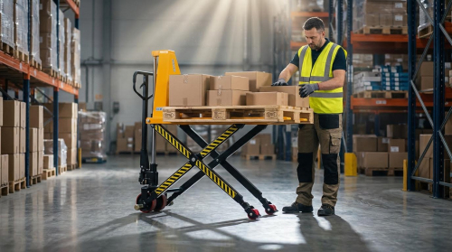
Low-Profile And Heavy-Duty Designs For Special Loads
Low-profile and heavy-duty pallet jacks used tailored geometries and components to handle special load cases without exceeding material or hydraulic limits. Ultra-low profile designs achieved very small lowered fork heights yet still reached capacities reported up to roughly 5500 kg, which required higher-strength fork sections and carefully tuned hydraulic cylinders. Heavy-duty variants with capacities in the 3000 kg to 5000 kg range often used thicker fork plates, reinforced webs, and higher-capacity pumps and seals. These designs balanced clearance, stroke, and wheel size so that even at maximum load the forks lifted enough to clear the floor without overstressing steel or hydraulics. Custom capacity options, for example 1000 kg, 1500 kg, or 2000 kg, allowed engineers to optimize material thickness and component sizing, avoiding unnecessary weight while still meeting the specified load rating with appropriate safety margins.
Applying Capacity In Operations And Maintenance
Operations teams needed to translate rated pallet jack capacities into safe, repeatable practice. This required disciplined reading of specifications, conservative loading techniques, and structured inspection routines. Engineering-based maintenance strategies then helped preserve the original capacity throughout the equipment life cycle. The following subsections described how to connect design limits with day-to-day use and long-term reliability.
Reading Nameplates, Labels, And OEM Specifications
Operators and engineers first confirmed lifting capacity from the pallet jack nameplate and OEM documentation. Labels typically stated maximum capacity in kilograms or pounds at a defined load center and fork length. For example, hydraulic hand pallet trucks from ONEN Forklifts carried ratings between 2000 kg and 5000 kg, while CUBLIFT low-profile models allowed 1000 kg to 3500 kg as standard, with ultra-low variants up to 5500 kg. Electric rider pallet jacks, such as Toyota end-controlled models, listed 6000 lb or 8000 lb capacities on level floors, which assumed correct load distribution and proper tire condition. Engineers cross-checked these values with parts lists and hydraulic schematics to verify that cylinder bore, pump pressure, and fork section modulus aligned with the stated rating.
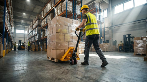
Capacity, Stability, And Safe Loading Practices
Safe application of capacity depended on both structural strength and stability margins. Operators positioned forks fully beneath the pallet, with the load center close to the specified value, typically near mid-fork length. Training programs emphasized never exceeding the marked capacity, because overloads increased hydraulic pressure beyond design limits and shifted the combined center of gravity toward the truck’s stability boundary. Loads were kept low, usually 20 mm to 50 mm above the floor, to reduce overturning moments during travel. Irregular or loosely stacked goods required strapping or wrapping to avoid shifting that could cause side tipping, even when the total mass remained below the nameplate rating.
Inspection, Wear Limits, And Component Replacement
Routine inspections preserved the original lifting capacity by preventing progressive degradation. Technicians checked hydraulic units for oil leaks, corrosion, and rod damage, because even minor leakage reduced effective pressure and thus usable capacity. Forks underwent visual and gauge-based checks for cracks, permanent bends, and excessive deflection under test loads; any deformation indicated local yielding and mandated removal from service. Wheel and roller diameters were measured against OEM values, with replacement triggered when wear exceeded about 6 mm of diameter loss, because reduced diameter altered geometry, increased rolling resistance, and compromised stability. Maintenance staff also verified straight forks, intact welds, and secure fasteners so that the rated loads from 2000 kg to 5000 kg on manual units, or up to 8000 lb on riders, remained structurally supported.
Predictive Maintenance, Sensors, And Digital Twins
Advanced fleets increasingly used sensor-based monitoring to manage lifting capacity over the life cycle. Load cells or pressure transducers on hydraulic circuits estimated applied load versus rated capacity in real time, flagging overload events in maintenance logs. Vibration and travel-distance data from wheel-end sensors supported wear prediction for polyurethane or nylon wheels used on CUBLIFT and ONEN-style trucks. In digital twin implementations, engineers modeled hydraulic pressure, fork stress, and contact forces to forecast remaining useful life under site-specific duty cycles. These predictive tools allowed planned replacement of cylinders, forks, and wheels before capacity loss or safety margins eroded, aligning operational practice tightly with the original engineering design limits.
Summary Of Key Capacity Criteria And Best Practices
Pallet jack lifting capacity depended on an integrated set of design, rating, and operational factors. Engineers defined rated capacity from hydraulic pressure limits, fork section strength, wheel loading, and stability at a specified load center and fork length. Typical manual hand trucks operated between 2000 kg and 5000 kg, while low-profile and ultra-low-profile designs, such as CUBLIFT units, reached up to about 5500 kg. Rider-type electric pallet jacks, like Toyota end-controlled models, handled loads up to roughly 3600 kg on level floors.
Industry practice required strict adherence to nameplate or label ratings for every application. Operators had to account for derating effects from off-center loads, oversized pallets, or degraded components. Uneven loading, excessive lift height, and poor floor conditions reduced the practical usable capacity below the nominal rating. Training programs and OSHA-aligned procedures emphasized verification of load mass, correct fork positioning, and maintaining forks about 20 mm to 50 mm above the floor during travel.
Maintenance played a direct role in preserving lifting capacity over the service life. Hydraulic leaks, low or contaminated fluid, and damaged piston or ram surfaces reduced effective pressure and lift capability. Worn load rollers or steer wheels, especially when diameter loss exceeded about 6 mm, compromised stability and increased contact stresses. Bent or cracked forks and damaged welds required immediate removal from service and replacement to keep loads within the engineered safety margin.
Future practice in material handling moved toward predictive maintenance and connected equipment. Sensors on hydraulic circuits, wheel modules, and structural members fed condition data into digital twins for capacity assurance. These tools allowed planners to forecast when wear would begin to affect safe capacity, rather than reacting after failures. A balanced strategy combined conservative capacity use, disciplined inspections, and data-driven maintenance, ensuring pallet jacks operated safely at or below their engineered lifting limits throughout their lifecycle.