Industrial work positioners allowed manufacturers to orient heavy or complex workpieces for welding, assembly, and inspection with high repeatability. This article examined core positioner functions and mechanical types, from simple tilt‑turn tables to multi‑axis systems integrated with robots and AGVs. It then detailed engineering selection criteria, including geometry matching, load and center‑of‑gravity control, motion sizing, and line layout constraints. Finally, it addressed safe operation, maintenance, digital monitoring, and strategic implementation guidelines for reliable, compliant, and efficient use of work positioners in modern production environments.
Core Functions And Types Of Work Positioners
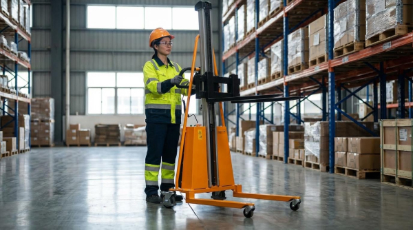
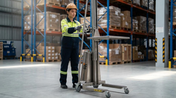
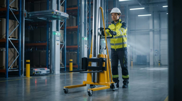
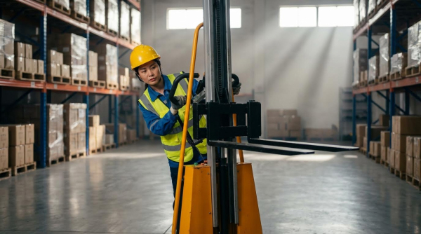
Core functions of industrial work positioners centered on orienting heavy or awkward workpieces so that operators or robots could access joints and features in optimal positions. In welding and assembly, positioners reduced manual handling, shortened non‑productive repositioning time, and improved joint quality by converting vertical or overhead work into flat or horizontal work. Engineers selected between multiple mechanical architectures and degrees of freedom to balance flexibility, stiffness, footprint, and cost. The correct choice depended on workpiece geometry, mass distribution, required process path, and integration with surrounding automation such as robots, cobots, or forklift drum attachments.
Role Of Positioners In Welding And Assembly
In welding applications, work positioners transferred weld seams into flat or ship positions to avoid vertical and overhead welding, which historically reduced defect rates and spatter. This reorientation improved puddle control, penetration consistency, and travel speed, directly increasing deposition efficiency. For construction machinery components such as excavator arms, X‑frames, and buckets, dedicated positioners allowed continuous circumferential or multi‑side welding without repeated crane handling. In assembly, positioners presented parts at ergonomic heights and angles, which lowered operator fatigue and musculoskeletal risk while stabilizing cycle times. They also created predictable, repeatable part locations that simplified the design of jigs, robots, and in‑line measurement systems.
Common Configurations And Degrees Of Freedom
Industrial positioners used standardized mechanical layouts that offered specific degrees of freedom and work envelopes. Manual units such as outrigger, tilt‑turn, and double‑post single‑turn types provided one or two controlled axes but could not achieve arbitrary spatial rotation because of limited kinematic chains. For heavy structural weldments, engineers frequently applied double‑pillar single‑rotation units for rectangular parts, roller frame types for long frames, and L‑type or C‑type double‑rotation positioners for axle boxes, X‑frames, and buckets. L‑type double‑rotation units provided two orthogonal 360° axes, giving high openness and accessibility around the part. More advanced double‑seat head‑and‑tail double‑rotary positioners added another rotational degree of freedom, enlarging the weldable space and enabling more complex multi‑side processing without re‑clamping.
Load, Center Of Gravity, And Stability Basics
Mechanical design and selection of a positioner always started from load and center‑of‑gravity calculations. Engineers specified rated capacity using the heaviest workpiece plus fixtures, then applied safety margins of approximately 20–30% to account for dynamic effects and uncertainty. Horizontal load capacity typically exceeded vertical capacity because overhung moments and bearing loads increased sharply when tilting large structures. During fixture design, locating points aimed to align the workpiece center of gravity with the rotation center to minimize unbalanced torque, vibration, and motor sizing. Auxiliary supports or roller rests stabilized irregular or long parts, reduced frame deflection, and protected tilt mechanisms from overload during extreme orientations.
Integration With Robots, Cobots, And AGVs
When integrated with robots or cobots, work positioners effectively acted as additional controlled axes that extended the reachable welding or assembly envelope. Engineers synchronized robot and positioner motion through coordinated path planning so that the torch or tool maintained constant travel speed and orientation while the part rotated or tilted. In advanced cells, walkie pallet truck or conveyors delivered workpieces to the positioner, which then locked into a defined datum using mechanical or sensor‑based docking to guarantee positional repeatability. Safety systems had to cover combined hazards from rotating structures and robot motion, using interlocks, zones, and communication protocols. Such integrated systems supported higher automation levels for large, irregular fabrications where fixed jigs alone could not provide sufficient access or ergonomics.
Engineering Selection Criteria For Work Positioners
Engineering teams needed clear criteria to select work positioners that matched structural complexity, process requirements, and safety rules. Proper selection improved weld quality, reduced rework, and controlled ergonomic risks. This section described how geometry, load, motion capability, and layout constraints guided rational positioner choice for industrial applications.
Matching Positioner Type To Workpiece Geometry
Engineers first analyzed workpiece geometry, weld seam distribution, and required access envelopes. For construction machinery structures, L‑type double‑rotation positioners suited rear axle boxes, excavator X‑frames, and similar box‑type parts because they provided two rotational degrees of freedom and high openness. C‑type double‑rotation units worked better for buckets and similar components where clamp design followed a curved or offset profile. Double‑pillar single‑rotation positioners matched elongated rectangular members such as excavator arms and roller frames, where one circumferential axis and optional column lifting covered all welds. Roller frame types supported long frames or cylindrical structures, allowing continuous circumferential seam welding at controlled speed. Selection always aimed to transform all critical welds into flat or ship positions while minimizing fixture complexity.
Load Ratings, Safety Factors, And Duty Cycles
Engineers calculated the maximum service load as the sum of the heaviest workpiece and all fixtures. They then applied a safety margin, typically 20–30%, to select a positioner whose rated capacity exceeded this value in both horizontal and vertical orientations. Horizontal load ratings usually exceeded vertical ratings, so designers checked each configuration separately, especially for tilt‑type tables. Duty cycle classification mattered for high‑volume welding cells because continuous rotation and frequent tilting increased thermal and mechanical stress on drives and gearboxes. For multi‑shift operation, they specified higher‑duty motors, robust reducers, and adequate cooling to prevent overheating and premature wear. Correct load and duty sizing reduced vibration, improved positional accuracy, and extended maintenance intervals.
Rotation, Tilt Range, And Speed Control Sizing
Rotation and tilt specifications depended on weld accessibility and process speed requirements. For complex structures, engineers preferred 360° continuous rotation and at least 0–90° tilt, with over‑travel if required to avoid overhead welding. Circumferential seam welding demanded careful sizing of rotation speed; teams derived required revolutions per minute from weld travel speed, workpiece diameter, and process type. Variable‑speed drives or frequency converters allowed fine adjustment for different diameters and procedures, improving bead quality and operator control. When integrating with robots, they coordinated axis speeds and accelerations so that positioner motion synchronized with robot path planning. Adequate braking torque and position holding capability ensured stability during high‑heat input operations and prevented drift under eccentric loading.
Footprint, Operator Height, And Line Layout
Layout decisions balanced accessibility, throughput, and safety. Designers evaluated the positioner footprint against available floor space, ensuring clear operator walkways and material flow paths. For heavy‑duty units handling large structural parts, they considered low working heights to keep welders on the floor where possible, adding scissor platform only when multi‑level access was unavoidable. Compact structures with good openness reduced blind spots and simplified crane or walkie pallet truck loading and unloading. In multi‑station lines, engineers aligned positioner infeed and outfeed directions with upstream cutting, forming, or machining cells to minimize handling steps. They also reserved space for electrical cabinets, maintenance access, and guarding, ensuring the overall cell met regulatory clearance and ergonomic requirements.
Operation, Safety, And Maintenance Practices
Operation, safety, and maintenance practices determined the real lifecycle cost and reliability of industrial work positioners. Robust procedures reduced unplanned downtime, protected operators, and preserved positioning accuracy. This section focused on pre‑startup checks, safe interaction with rotating systems and robots, structured maintenance, and the growing role of digital monitoring and predictive maintenance.
Pre‑Startup Checks And Clamping Verification
Pre‑startup checks ensured mechanical integrity and electrical safety before any motion. Operators inspected rotating and tilting mechanisms for smooth, jam‑free travel and verified that all structural bolts, anchors, and faceplate fasteners were tight. Electrical inspections covered power cables, plugs, control panels, emergency stops, and indicator lamps, confirming correct function and absence of visible damage. During clamping, operators selected fixtures that matched workpiece geometry and mass, then positioned the workpiece so its center of gravity aligned closely with the rotation axis. For irregular or long workpieces, auxiliary supports prevented sagging, vibration, or overturning during tilt and rotation. A short no‑load and then low‑speed loaded trial run validated that there was no interference, abnormal vibration, or noise before welding or assembly started.
Safe Use With Rotating Machinery And Robots
Safe use around rotating positioners relied on controlled access to hazard zones and disciplined communication. Employers trained personnel to recognize struck‑by and pinch or crush zones created by rotating tables, arms, and robot superstructures. Facilities marked these zones using floor lines, railings, or barriers; where barriers were infeasible, clear painted boundaries and warning signs defined the exclusion area. Before entering an operator’s blind area near a rotating positioner or robot, workers had to notify the operator and receive confirmation that motion stopped and remained inhibited. When several machines operated with overlapping work envelopes, a coordination system assigned right‑of‑way and prevented conflicting moves. Procedures required full stop and energy isolation before any intervention, with emphasis on PPE, tight clothing, controlled hair, and adherence to emergency stop and evacuation protocols defined by site safety standards.
Lubrication, Inspection, And Fault Handling
Planned lubrication and inspection programs extended positioner service life and preserved accuracy. Maintenance teams lubricated gearboxes, bearings, tilt mechanisms, and drive trains at defined intervals using manufacturer‑specified oils and greases, after cleaning fittings to avoid contamination. Mechanical inspections checked frame welds, arms, turntables, and guide elements for cracks, deformation, or wear, and verified flatness and cleanliness of faceplates and T‑slots. Technicians inspected motors, reducers, chains, gears, and guide rails, confirming correct tension, backlash, oil levels, and corrosion protection. Electrical maintenance included cleaning cabinets, verifying insulation resistance above specified limits, and checking contactors, relays, and terminal tightness. When operators detected abnormal noise, vibration, or workpiece looseness, procedures required immediate stop, power isolation, and diagnosis. Staff addressed simple issues like tightening or lubrication locally, while faults such as motor failure, control errors, or hydraulic leaks triggered specialist intervention under lockout or tagout conditions.
Digital Monitoring And Predictive Maintenance
Digital monitoring transformed work positioner maintenance from reactive to predictive strategies. Modern systems used sensors on motors, gearboxes, and structural nodes to track vibration, temperature, current draw, and rotational speed in real time. Data streamed to controllers or plant networks, where trend analysis and thresholds highlighted emerging problems such as bearing degradation, misalignment, or overload conditions. Integrated counters recorded duty cycles, start‑stop events, and accumulated rotation or tilt time, supporting condition‑based maintenance rather than fixed‑interval servicing. Advanced implementations combined these data with welding or assembly programs to synchronize positioner health with production planning. Predictive algorithms then recommended lubrication, component replacement, or alignment checks before failure, improving availability and reducing spare‑parts emergencies. Clear dashboards and alarms provided operators and maintenance engineers with actionable information while maintaining compliance with safety and functional integrity requirements.
Summary And Strategic Implementation Guidelines
Industrial work positioners have played a central role in bridging the gap between manual welding, semi-automation, and robotic systems. They improved weld quality by transforming vertical and overhead seams into flat or ship positions and reduced rework rates and porosity. Correctly matched positioners also lowered labor intensity and stabilized cycle times, which supported lean manufacturing initiatives.
From an engineering perspective, the decisive selection factors remained workpiece geometry, mass, and center of gravity. L‑, C‑, double‑pillar, and head‑and‑tail double rotary designs each suited particular structural forms such as excavator arms, X‑frames, buckets, and roller frames. Designers needed to verify load capacity in both horizontal and vertical orientations with at least a 20–30% safety margin that included fixtures. Specifying tilt range, rotational speed, and duty cycle against process travel speed and heat input requirements ensured consistent weld penetration and bead appearance.
Strategic implementation required integrating positioners into line layout, operator ergonomics, and safety systems. Plants benefited when they standardized fixture interfaces, clamping philosophies, and control schemes across families of parts, which reduced changeover time and training effort. Pre‑startup checks, verified grounding, structured lubrication plans, and periodic structural inspections extended service life and prevented catastrophic failures. For mixed manual–robotic cells, coordination logic, interlocks, and clearly defined hazard zones around rotating structures remained essential.
Looking forward, digital monitoring and predictive maintenance would increasingly shape positioner deployment. Adding sensors for vibration, motor current, temperature, and rotation feedback enabled early detection of misalignment, bearing wear, and overload conditions. Data from these sensors could feed plant MES or cloud platforms to optimize preventive maintenance intervals and correlate positioner behavior with weld quality metrics. Even as fully robotic handling expanded, versatile multi‑axis positioners would remain critical for irregular, heavy, or low‑volume parts where full automation was not economical. A balanced roadmap combined robust mechanical design, conservative sizing, disciplined maintenance, and gradual layering of sensing and analytics capabilities.