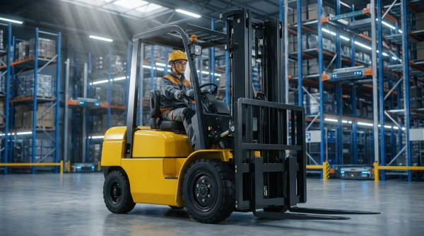
Electric forklift performance depended on the tight integration of drive electronics, energy systems, and safety controls across the truck. This article examined how core drive technologies and speed control strategies shaped traction, curve handling, and regenerative braking behavior under real warehouse duty cycles. It then linked higher travel speeds to stability measures, operator-assist systems, and regulatory compliance with OSHA and ISO 3691-1. Finally, it compared lithium-ion and lead-acid platforms, maintenance and IoT-enabled uptime, and lifecycle cost and sustainability trade-offs to support robust specification of high-performance electric forklifts.
Core Drive Technologies And Speed Control
Core drive technologies defined the performance envelope of electric forklifts. Speed control strategies determined how safely and efficiently that performance translated into real warehouse throughput. Modern fleets relied on tightly integrated motor, inverter, and sensor systems rather than simple contactor logic. Understanding these elements helped engineers specify trucks that balanced speed, stability, and reliability.
AC Vs. DC Traction Motors In Modern Fleets
Modern high-duty electric forklifts predominantly used three-phase AC traction motors with IGBT-based inverters and PWM control. These systems operated efficiently over wide speed ranges and paired well with lithium-ion batteries that delivered stable voltage under load. Legacy fleets still ran DC traction motors with MOSFET choppers, which provided strong low-speed torque but required brush and commutator maintenance. AC drives reduced mechanical wear, supported regenerative braking more effectively, and simplified sealed designs for cold storage or dusty sites.
AC traction systems enabled finer speed maps, including creep modes and smooth acceleration ramps, because controllers modulated torque precisely at low speeds. DC systems could emulate some of this behavior but usually with coarser resolution and higher heat generation. As fleets migrated to AC, operators experienced more consistent travel speed over a shift, even as battery state of charge declined. This consistency supported higher pallet-per-hour rates without increasing accident risk.
Dual-Motor Drives, Curve Control, And Traction
Dual-motor drive architectures used an independent AC motor on each drive wheel, controlled by a coordinated inverter pair. This configuration allowed the controller to vary torque side-to-side during turns, improving curve control and reducing understeer on smooth or wet floors. By modulating inner and outer wheel speeds, dual-motor systems limited lateral slip and reduced the risk of sideways skidding with elevated loads. Operators perceived this as more predictable steering response at higher travel speeds.
Curve speed control algorithms linked steering angle sensors to the traction controller. When the steering angle exceeded a threshold, the controller automatically derated maximum travel speed to keep lateral acceleration within safe limits. This strategy reduced tip-over risk from centrifugal forces, aligning with safety practices highlighted in industry standards and Royal Forklift style guidelines. On mixed indoor-outdoor trucks, traction control logic also reacted to wheel-speed differences to manage grip on wet ramps and dock plates.
Closed-Loop Feedback, Sensors, And PID Tuning
Closed-loop speed control relied on wheel encoders or tachometers to measure actual wheel speed in real time. The controller compared measured speed with the requested setpoint and used PID algorithms to adjust motor torque. Properly tuned PID gains allowed the truck to hold commanded speed despite slope, load variation, or tire slip. Poor tuning caused oscillations, sluggish response, or overshoot that could destabilize tall loads.
Modern systems integrated additional sensors such as steering angle, load pressure, and sometimes accelerometers. These inputs adjusted speed limits dynamically, for example derating speed under heavier loads to preserve stopping distance. Acceleration and deceleration ramps implemented within the control loop smoothed transitions, reducing mast sway and fork tip oscillations. Annual sensor recalibration and occasional retuning after major component changes maintained control accuracy and regulatory compliance.
Regenerative Braking And Thermal Management
Regenerative braking converted vehicle kinetic energy back into electrical energy, feeding it into the traction battery. This process reduced mechanical brake usage, lowered pad and drum wear, and stabilized truck behavior during deceleration. Lithium-ion batteries accepted regen currents more effectively than lead-acid packs, which improved energy recovery and kept speed control consistent late in the shift. Controlled regen profiles also minimized abrupt deceleration that could shift or damage palletized loads.
Thermal management played a critical role in maintaining drive system reliability under high-duty cycles. IGBT inverters and traction motors generated heat during both motoring and regeneration, especially at high currents. Manufacturers used heat sinks, forced-air cooling, or liquid-cooled plates to keep junction and winding temperatures within design limits. Well-managed thermal behavior reduced derating events, extended component life, and helped fleets sustain top travel speeds such as 13–16 km/h without overheating during continuous multi-shift operation.
Safety, Stability, And Compliance At Higher Speeds
High travel speeds increased throughput in electric forklift operations but raised risk levels sharply. Engineering controls therefore focused on dynamic speed management, enhanced stability functions, and verified regulatory compliance rather than relying only on operator behavior. Modern trucks integrated sensors, software, and telematics to enforce safe envelopes in real time, even under mixed loads, changing gradients, and dense pedestrian traffic. The following subsections described how load-based control, motion management, perception systems, and standards alignment worked together to keep high-speed fleets safe and compliant.
Load-Weight-Based Speed Limiting And LWS Design
Load-weight-based speed limiting (LWS) used hydraulic pressure sensors or load cells to estimate actual payload on the forks. The controller then applied a speed map that reduced maximum travel speed and acceleration as load increased, maintaining stopping distance and lateral stability within design margins. Engineers typically calibrated breakpoints using rated capacity, mast height, and tire type, for example capping speed to 5–7 km/h near nominal capacity. Closed-loop integration with braking and mast sway damping further reduced product damage and tip-over risk when handling heavy or high-center-of-gravity pallets.
Cornering, Rollback, And Slope Speed Management
Cornering control relied on steering angle sensors and dual-motor drives to limit speed as lateral acceleration approached stability thresholds. Controllers automatically decelerated when steering angle exceeded predefined values, preventing tip events from centrifugal forces in tight turns. Rollback control monitored wheel speed and slope direction, then applied controlled torque to prevent uncontrolled reverse motion on ramps. Slope speed limiting reduced maximum travel speed uphill and downhill based on gradient estimation, maintaining traction, predictable stopping distances, and compliance with site-specific ramp policies.
Vision, Radar, And Telematics For Safer Operation
Camera systems, reversing radar, and ultrasonic sensors expanded the operator’s effective field of view, particularly in high racking and blind intersections. Rear radars detected obstacles within a defined envelope and triggered graduated alarms or automatic deceleration when distance thresholds were crossed. Telematics platforms geo-fenced speed zones around aisles, loading docks, and pedestrian crossings, enforcing lower limits and logging overspeed or near-miss events. Fleet managers used heatmaps, event logs, and battery analytics to refine speed maps, adjust training, and validate that safety interventions reduced impacts and incident rates over time.
Meeting OSHA And ISO 3691-1 Speed Requirements
OSHA rules emphasized safe operation, daily inspections, and proper training rather than prescribing a single numeric speed limit. ISO 3691-1, by contrast, defined design and performance requirements for industrial trucks, including braking performance, stability testing, and expectations for speed management functions. Automated speed control, LWS, and curve control helped fleets demonstrate that actual operating speeds remained compatible with stopping distances and stability criteria under rated conditions. Documented telematics data, maintenance records, and operator refresher training supported audit readiness and reduced liability exposure after incidents.
Energy Systems, Uptime, And Lifecycle Costs
Energy architecture dictated how fast electric forklifts operated, how long they stayed on shift, and what they cost over their life. Lithium-ion systems supported higher sustained speeds and duty cycles, while lead-acid constrained performance as voltage sagged. Charging strategy, maintenance intensity, and digital fleet management determined real-world uptime more than nameplate battery capacity. Lifecycle cost analysis needed to integrate energy, maintenance, incentives, and residual value rather than focus on purchase price alone.
Lithium-Ion Vs. Lead-Acid: Speed And Duty Cycles
Lithium-ion batteries delivered a flatter voltage curve, so forklifts maintained target travel speed and lift performance late into the shift. Lead-acid units experienced voltage sag under high current draw, which forced conservative speed maps and reduced acceleration as state of charge dropped. Typical lithium-ion packs achieved 2,000–3,000 cycles, while lead-acid packs reached roughly 500–1,500 cycles, depending on depth of discharge and maintenance quality. For high-duty operations running close to continuous, lithium-ion supported opportunity charging and shorter breaks, which increased pallet throughput and reduced the number of trucks required.
Energy cost comparisons favored electric over internal combustion, but within electric fleets lithium-ion also improved efficiency. A 2.5-ton electric forklift at 60% load drew around 7.8 kW, which translated to roughly $0.78 per operating hour using 2025 U.S. industrial tariffs. Lead-acid systems with higher internal resistance ran slightly less efficiently and lost more energy as heat during charge and discharge. Lithium-ion chemistry also accepted regenerative braking energy more effectively, enabling aggressive regen strategies without overheating or premature degradation. This combination of stable speed, strong regen acceptance, and longer cycle life reduced both downtime and lifetime battery cost per pallet moved.
Charging Strategies, Smart Chargers, And V2G
Charging strategy strongly influenced uptime and battery longevity. Lithium-ion packs supported 1–2 hour full charges and frequent opportunity charging during breaks, which enabled near 24/7 operation with a single pack. Lead-acid batteries required 8–10 hours for full charging plus cool-down periods, so multi-shift operations often needed battery swaps and dedicated charging rooms. Smart chargers optimized charge profiles, limited peak current draw, and logged charge history for warranty and diagnostics. They implemented staged constant-current and constant-voltage phases, temperature compensation, and equalization routines for lead-acid when required.
Advanced fleets used networked chargers integrated with warehouse energy management systems. These systems staggered charging starts to avoid demand spikes and shifted charging to off-peak tariff windows where possible. Emerging vehicle-to-grid (V2G) functions allowed idle forklifts to export a few kilowatts for peak shaving, generating incremental utility credits over a year. Fast-charging infrastructure at 350 V supported partial charges adding roughly 50% capacity in about 10 minutes, which suited intense operations such as foundries or cross-dock hubs. Proper charger selection and layout also improved safety by minimizing cabling across travel paths and ensuring compliance with electrical and fire codes.
Maintenance, Predictive Analytics, And IoT Fleets
Maintenance regimes differed significantly between electric energy systems and internal combustion platforms. Electric powertrains contained far fewer moving parts, which reduced scheduled service tasks and unplanned downtime. Lead-acid fleets required routine electrolyte checks, watering, and terminal cleaning, while lithium-ion packs operated largely maintenance-free aside from periodic inspections. Under OSHA rules, daily checks still covered items such as cables, connectors, and visible damage to battery enclosures. Following Industrial Battery Council practices for lead-acid—full charge before watering, distilled water only, and periodic equalization—extended service life and reduced failure risk.
IoT-enabled forklifts and chargers transformed maintenance from reactive to predictive. Embedded sensors monitored battery temperature, voltage dispersion across cells, charge acceptance, and vibration signatures from drive and lift components. Telematics platforms aggregated this data, flagged anomalies, and predicted component replacement windows, which helped avoid catastrophic failures and unscheduled stoppages. Fleets that implemented predictive analytics reported maintenance cost reductions on the order of 25–30% and higher effective uptime. Digital maintenance logs also simplified regulatory audits and warranty claims by providing traceable histories of checks, alarms, and interventions.
TCO, Incentives, And Sustainability Trade-Offs
Total cost of ownership (TCO) for electric forklifts depended on acquisition cost, energy use, maintenance, and residual value. Electric units typically had higher upfront prices than internal combustion models, especially with lithium-ion packs,
Summary: Specifying High-Performance Electric Forklifts
Specifying high-performance electric forklifts required a system view of traction, safety, energy, and lifecycle economics. Modern AC traction with closed-loop speed control, curve control, and regenerative braking delivered precise handling, higher pallet throughput, and lower component wear than legacy DC systems. Dual-motor drives, load-weight-based speed limiting, and tuned acceleration ramps helped maintain stability at travel speeds up to 16 km/h while cutting mast sway and product damage. These capabilities aligned fleets with OSHA guidance and ISO 3691-1 expectations for controlled speeds and predictable stopping distances.
Energy architecture strongly influenced uptime and cost. Lithium-ion packs, combined with smart and opportunity charging, supported 1–2 hour recharge windows and stable performance over 2,000–3,000 cycles, outperforming lead-acid in heavy multi-shift duty. Predictive maintenance, IoT sensors, and telematics dashboards reduced unplanned downtime by up to 30% and enabled geo-zoned speed limits, operator profiles, and data-backed tuning of ramp rates and regen levels. Total cost of ownership analyses consistently showed electric trucks undercutting LPG and diesel over 10,000 operating hours, while zero local emissions, lower noise, and V2G potential strengthened sustainability cases.
In practice, specifiers balanced peak speed against aisle geometry, racking height, and floor conditions, then matched trucks with appropriate curve control, slope limiting, and visibility aids such as cameras and reversing radar. They also considered regulatory trends, incentives, and future technology such as silicon-carbide inverters and next-generation batteries to avoid stranded assets. A balanced specification treated forklifts as connected assets rather than standalone machines, integrating speed control, safety functions, energy strategy, and digital maintenance into one coherent performance envelope.