Drum dollies played a critical role in industrial facilities that handled heavy drums, cylinders, and barrels. They combined engineered frames, platforms, and casters to move loads up to roughly 500 kg with controlled effort and high stability. This article examined drum dolly basics, engineering design factors, and practical selection criteria, then linked these to integration, maintenance, and safety practices across warehouses and process plants. It provided engineers with a structured framework to specify, deploy, and maintain drum dollies that supported safe, efficient material handling in demanding environments.
Drum Dolly Basics and Core Functions
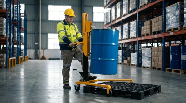
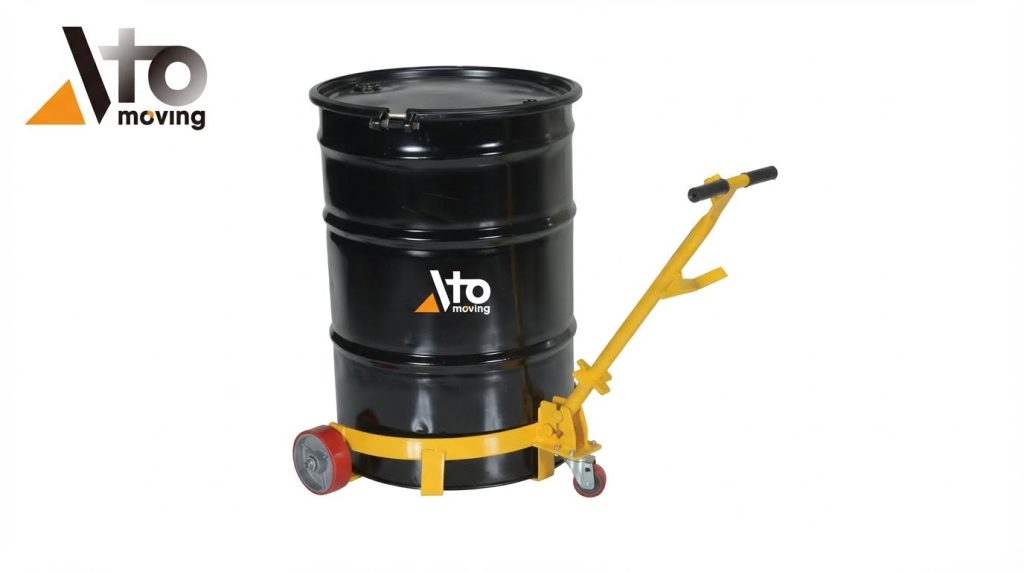
Drum dollies served as compact, wheeled platforms that supported and moved heavy drums with minimal manual effort. Industrial facilities used them to transfer chemicals, oils, food ingredients, and waste between storage, processing, and shipping areas. By placing the drum’s mass close to the floor and distributing it over multiple casters, dollies reduced tipping risk and manual lifting. They also standardized handling of different drum types, improving workflow and lowering injury rates.
What Is a Drum Dolly in Industrial Operations
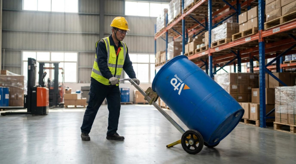
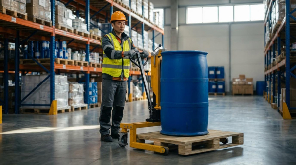
In industrial operations, a drum dolly functioned as a dedicated transport aid for cylindrical containers such as steel or plastic drums. The dolly’s frame cradled the drum base, while swivel casters enabled controlled movement in tight aisles and around equipment. Operators typically pushed or pulled the loaded dolly rather than tilting or rolling the drum itself, which reduced strain and impact loads. Plants used drum dollies at filling lines, decanting stations, and warehouses to move drums between pallets, racks, and process equipment safely and efficiently.
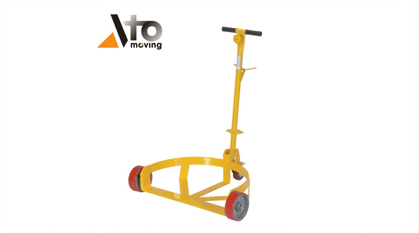
Unlike general-purpose carts, drum dollies centered the load and matched the footprint of standard drum diameters, improving stability. Low-profile designs kept the drum’s center of gravity close to the floor, which limited overturning moments during starts, stops, or turns. In hazardous material service, properly specified dollies supported spill control strategies by enabling smoother, more predictable drum motion. As part of a broader material handling system, they bridged gaps between fixed equipment, conveyors, and storage locations.
Typical Drum Types, Sizes, and Load Ranges
Drum dollies usually carried standard 110 liter and 205 liter drums, corresponding to 30 gallon and 55 gallon capacities. Frames commonly accepted drum diameters around 584 millimeters, matching typical steel chemical drum dimensions. Designs accommodated both closed-head and open-head drums, as well as compatible plastic and fiber variants, provided the base diameter fit the support ring. Load ratings in industrial-grade units typically ranged up to 450–500 kilograms, covering fully loaded 205 liter drums containing high-density liquids.
Some platforms supported multiple drum sizes using adjustable rings or segmented cross bases that engaged different diameters. Engineers verified that the maximum drum mass, including product and any mixing hardware, remained below the dolly’s rated capacity with an appropriate safety factor. Where facilities handled gas cylinders or specialty containers, they specified dollies with tailored cradles or restraints. This alignment between drum geometry, mass properties, and dolly rating ensured predictable handling performance and regulatory compliance.
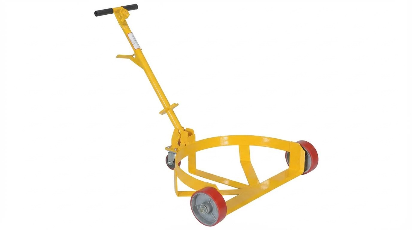
Key Components: Frame, Platform, and Casters
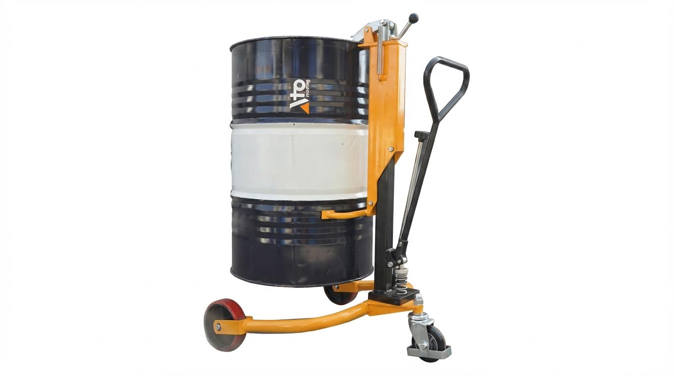
The frame formed the structural core of a drum dolly and typically used welded steel sections or 3 millimeter sheet with reinforced cross bases. Circular or polygonal rings supported the drum base uniformly, preventing local deformation and reducing point loads on thin drum walls. Low overall height, often near 165 millimeters, allowed operators to load drums without significant lifting or tilting. Powder-coated or otherwise protected surfaces resisted corrosion and abrasion in wet or chemical-prone environments.
The platform integrated the frame with the caster mounting points, distributing loads evenly to each wheel. Industrial designs used four casters arranged symmetrically to improve balance and maintain contact on uneven floors. Casters with diameters around 76 millimeters and widths near 32 millimeters provided low rolling resistance and adequate load distribution. Swivel casters enhanced maneuverability, while material choices such as polyolefin, polyurethane, or rubber matched specific floor conditions and contamination risks.
Bolted caster attachment simplified replacement and inspection, which supported preventive maintenance programs. Engineers evaluated wheel hardness, bearing type, and swivel design to manage push forces and vibration transmission to the drum. Where floor irregularities or thresholds existed, larger-diameter casters and reinforced brackets reduced impact loads and extended service life. Together, the frame, platform, and casters defined the dolly’s load capacity, stability envelope, and suitability for a given industrial environment.
Engineering Design and Performance Factors
Engineering design of drum dollies balanced structural strength, maneuverability, and operator safety. Industrial users evaluated frame geometry, caster configuration, and materials against defined load cases, floor conditions, and chemical exposure. Performance criteria typically included static and dynamic load capacity, push–pull forces, and stability margins during starts, stops, and turns. Sound design reduced whole‑body strain, minimized tipping risks, and extended service life under continuous duty.
Frame Geometry, Materials, and Load Capacity
Frame geometry governed how loads transferred from the drum into the casters. Circular or cross-base frames supported the drum chime or base uniformly, preventing point loading and local deformation. Designers specified plate thicknesses near 3 mm for heavy-duty units, with welded cross members to resist torsion during turning. Reinforced rims and gussets around caster mounts limited deflection and maintained caster alignment under 450 kg to 500 kg loads.
Steel remained the dominant frame material because it provided high yield strength, good weldability, and predictable fatigue behavior. Engineers selected structural or low-alloy steels according to required load ratings and impact conditions. For general industrial use, powder-coated carbon steel offered adequate corrosion protection and abrasion resistance. Where weight reduction mattered, designers sometimes considered aluminum, but verified buckling resistance and joint design carefully.
Load capacity ratings reflected conservative design assumptions and test data. Engineers considered worst-case static loading, dynamic factors from pushing over thresholds, and occasional shock loads. Safety factors typically ranged between 1.5 and 3.0 relative to ultimate capacity, depending on internal standards and regulatory requirements. Manufacturers validated ratings by proof-loading prototypes to at least the declared capacity and checking permanent deformation, weld integrity, and caster mounting performance.
Caster Selection, Floor Conditions, and Stability
Caster selection directly affected rolling resistance, maneuverability, and vibration transmitted to the drum. Designers chose wheel diameter, tread width, and bearing type based on floor flatness, joint spacing, and debris levels. For heavy drums, wheel diameters near 75 mm to 125 mm reduced rolling resistance and eased transitions over expansion joints. Wider treads distributed contact pressures and reduced local floor damage, especially on coated concrete.
Wheel materials needed to match floor conditions and chemical exposure. Polyolefin or polyurethane wheels provided low rolling resistance on smooth concrete and resisted typical warehouse chemicals. Rubber treads offered better damping on rougher floors, but increased push forces and wear. Swivel casters on all four corners maximized maneuverability in tight aisles, while optional brakes or directional locks improved control on slopes or during loading.
Stability depended on wheelbase width, drum center-of-gravity height, and caster placement relative to the drum footprint. Low-profile designs kept the drum close to the floor, reducing overturning moments during sudden stops or sideways impacts. Engineers checked tipping thresholds by comparing overturning moments from lateral forces to restoring moments from the dolly footprint. They also considered dynamic effects when operators turned quickly or hit floor irregularities at speed.
Ergonomics, Push Forces, and Operator Safety
Ergonomic design aimed to keep push and pull forces within recognized occupational guidelines. Engineers estimated required forces using caster rolling resistance coefficients, drum mass, and floor conditions. For well-maintained floors and suitable casters, starting forces for a 450 kg drum cart could remain within safe manual handling limits for a single operator. Designers minimized friction by specifying precision bearings and ensuring accurate caster alignment.
Handle geometry and operator interface influenced posture and control. Where integrated handles existed, they positioned grip heights roughly between 900 mm and 1100 mm to keep operators’ arms near neutral positions. Smooth, continuous push paths reduced the need for sudden directional changes, which increased peak forces and strain. Non-slip surfaces and clear access around the drum reduced the risk of foot injuries and awkward twisting.
Safety features complemented ergonomic design. Brakes or wheel chocks controlled motion on sloped floors or during loading and unloading near ramps. Clear labeling of maximum load capacity and any slope restrictions informed operators about safe use limits. Training programs reinforced correct techniques, such as pushing rather than pulling where possible, and avoiding rapid acceleration or deceleration with fully loaded drums.
Corrosion Resistance and Chemical Compatibility
Corrosion resistance became critical where facilities handled chemicals, oils, or outdoor storage. Powder-coated steel frames provided a durable barrier against moisture and incidental spills, slowing general corrosion. Engineers specified coating thickness and curing conditions to achieve predictable impact and abrasion resistance. For aggressive environments, they evaluated galvanizing or stainless steel pallet jack for longer life and reduced maintenance frequency.
Caster and wheel materials required careful compatibility checks with handled substances. Polyolefin and polyurethane wheels resisted a wide range of industrial chemicals and cleaning agents. However, prolonged exposure to strong solvents or high temperatures could degrade certain polymers, so designers reviewed chemical resistance charts during selection. Metallic components such as bearings and fasteners sometimes required stainless grades or protective plating.
Designers also considered cleaning and decontamination procedures. Smooth, accessible surfaces without deep crevices simplified wash-down and reduced residue accumulation. Drainage paths prevented standing liquids from concentrating corrosive agents at welds or joints. Where facilities transported hazardous materials, engineers aligned material choices with relevant safety and environmental regulations, ensuring that dolly components did not react with or absorb transported substances.
Selection, Integration, and Maintenance Practices
Engineering teams needed a structured approach when specifying drum dollies for industrial facilities. Proper selection, integration, and maintenance reduced injury risk, protected product quality, and supported continuous operations. This section focused on engineering criteria for model selection, interface with existing material-handling systems, and lifecycle maintenance strategies, including documentation and training. It provided a framework that plants could adapt to chemical, food, pharmaceutical, or general manufacturing environments.
Choosing the Right Drum Dolly for Your Plant
Selection started with defining drum characteristics: material, diameter, height, and maximum filled mass. Typical industrial dollies supported up to 450–500 kg, so engineers verified worst-case drum mass, including liquid density and overfill margins. Frame geometry had to match drum diameter, for example around 584 mm for 205 L drums, with full circumferential or cross-base support to avoid point loading. Caster type depended on floor conditions and duty cycle; polyurethane or polyolefin casters handled smooth concrete and resisted wear, while larger diameters reduced rolling resistance. Plants handling mixed drum sizes or plastic and steel drums evaluated adjustable cradles or interchangeable rings to maintain lateral stability without excessive clearance.
Integrating Dollies with Conveyors and AGVs
Integration with conveyors and automated guided vehicles required consistent interface heights and predictable center-of-gravity locations. Engineers compared dolly overall height, often around 165 mm, with conveyor top-of-roller elevation to ensure safe transfer without impact or edge drop. Low-profile frames improved stability but had to maintain sufficient ground clearance for expansion joints and floor irregularities. When AGVs or tuggers moved dollies, coupling points, tow bars, or hitch fixtures needed defined geometry and strength consistent with maximum train mass and acceleration. Plants also standardized drum orientation and traffic lanes so manual dollies, conveyors, and AGVs shared clear routes, minimizing cross-traffic and reducing collision risk in tight aisles.
Inspection, Preventive Maintenance, and Records
Effective maintenance programs combined daily checks, periodic inspections, and documented records. Operators performed pre-use checks on casters, ensuring free rotation, intact treads, and secure fasteners, while scanning the frame for visible deformation or cracked welds. Weekly or monthly inspections went deeper, verifying caster swivel bearings, brakes, and any straps or retention devices, and confirming that the dolly still met its rated load capacity. Maintenance teams cleaned frames and casters, removed debris, and lubricated moving joints using compatible greases to prevent corrosion and seizure. Facilities kept maintenance logs per dolly ID, capturing inspection dates, findings, repairs, and component replacements, which supported audits, lifecycle cost analysis, and replacement planning.
Safety Compliance and Operator Training
Safety compliance relied on aligning dolly use with applicable occupational safety regulations and internal handling standards. Procedures defined maximum allowable load, required personal protective equipment, and rules for handling hazardous or volatile contents to prevent spills. Training programs covered correct loading, positioning drums centrally in the cradle, and verifying that retention systems such as straps or clamps engaged before movement. Operators learned proper push techniques, preferred pushing rather than pulling, maintaining clear sightlines, and controlling speed on slopes or transitions. Refresher training and periodic assessments ensured that actual practices matched written procedures, reducing strain injuries, tip-over incidents, and non-compliance during regulatory inspections.
Summary and Practical Takeaways for Engineers
Drum dollies played a critical role in industrial facilities by enabling safe, low-effort movement of heavy cylindrical containers. Well-engineered units used reinforced steel frames, low-profile circular platforms, and industrial-grade swivel casters to keep drums stable while maneuvering in tight spaces. Typical capacities ranged up to about 450–500 kg per drum, which covered common 110 L and 205 L containers in logistics, chemical, and manufacturing environments.
For engineering teams, the primary design and selection drivers included frame geometry, caster type, and compatibility with floor conditions and drum materials. Corrosion resistance and chemical compatibility mattered in chemical, pharmaceutical, and food plants, where coatings and material choices affected service life and contamination risk. Ergonomic factors, such as required push forces and handle design, directly influenced musculoskeletal risk and compliance with occupational safety guidelines.
In practice, engineers needed to specify dollies by drum size range, verified load rating with safety margins, and caster configuration that matched surface roughness, slopes, and turning radii. Integration with conveyors, automated guided vehicles, and storage layouts required attention to overall dolly height, turning envelope, and parking or staging concepts. Preventive maintenance programs with documented inspections, lubrication, and part replacement schedules supported uptime, extended asset life, and reduced incident rates.
Looking ahead, facilities increasingly combined conventional drum dollies with automation, improved ergonomic aids, and smarter maintenance tracking. However, the fundamentals remained unchanged: structurally sound frames, appropriate casters, and disciplined inspection and training programs. Engineers who treated drum dollies as engineered load-handling devices, rather than simple carts, achieved safer operations, lower life-cycle costs, and more reliable material flow.