Scissor lifts relied on a compact, vertically telescoping linkage to provide safe elevated access for people, tools, and materials. Their design combined structural mechanics, hydraulic actuation, and control engineering to meet strict load, stability, and safety requirements. This article examined the core architecture of scissor mechanisms, quantified load paths and failure modes, and addressed hydraulic sizing, control logic, and digital integration. It concluded with design implications for industrial deployment, including reliability, regulatory compliance, and readiness for data-driven maintenance and collaborative automation.
Fundamental Scissor Lift Architecture
Fundamental scissor lift architecture defined the load path, motion envelope, and integration of hydraulics with structure. Engineers linked the scissor mechanism, platform, and base as a single kinematic chain that converted cylinder stroke into vertical lift. Design choices in arm geometry, platform framing, and material selection directly affected capacity, stiffness, and stability. A rigorous architectural definition therefore preceded detailed strength and safety checks.
Primary Structural Components and Kinematics
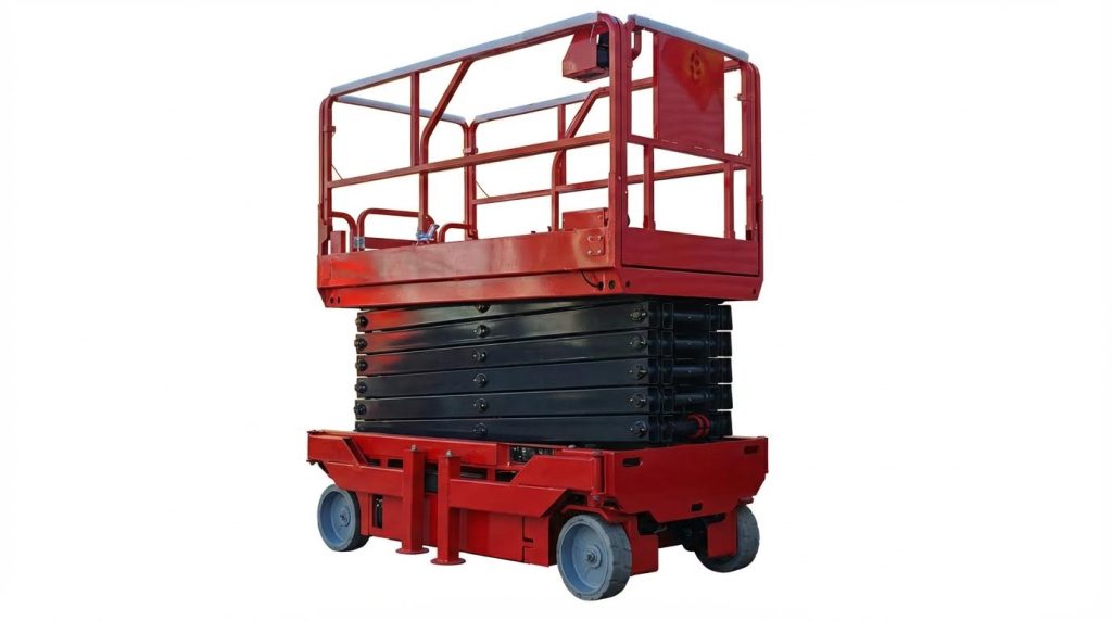
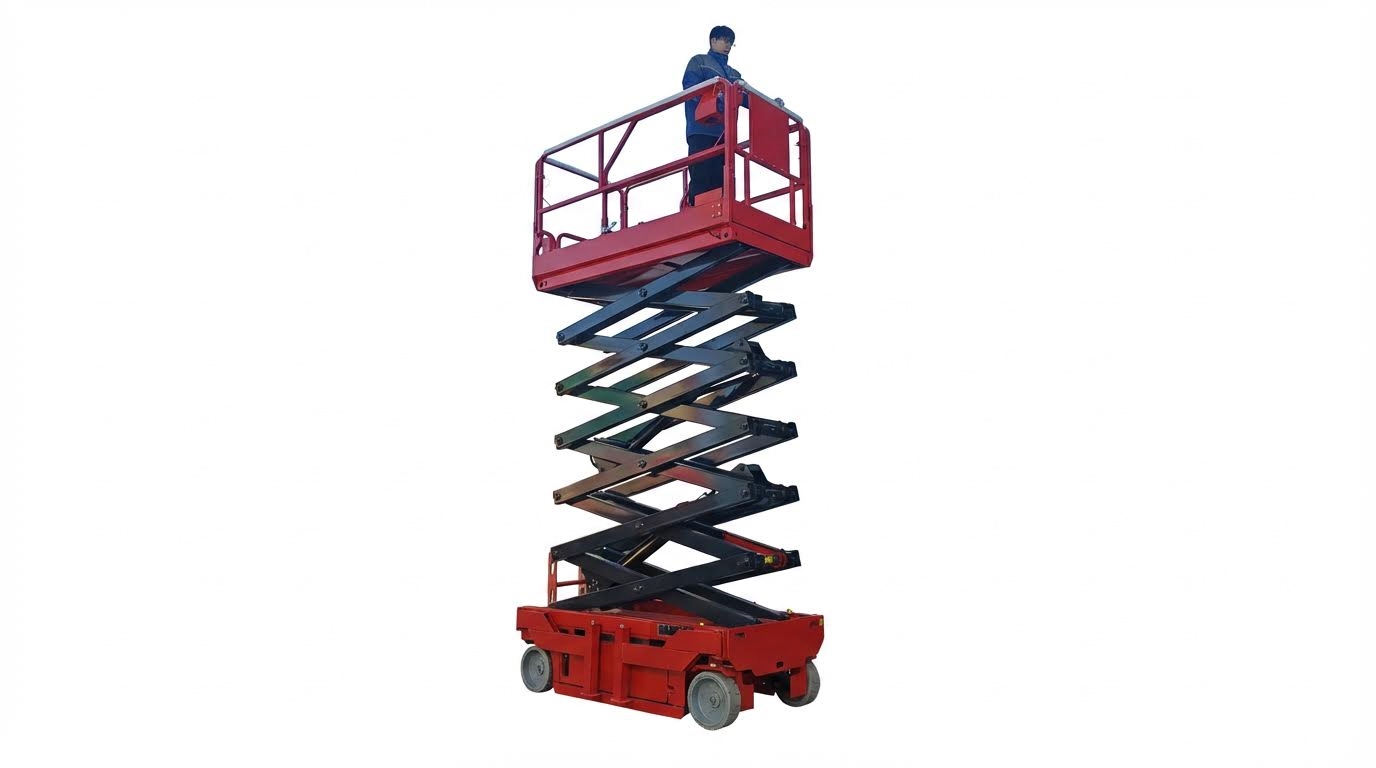
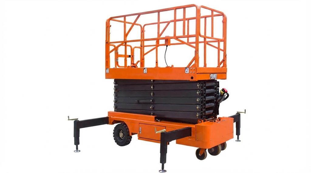
A fixed scissor lift typically consisted of a base frame, crossed scissor arms, a top platform, and one or more actuators. The arms connected through pinned joints and sliding or rolling supports, which constrained motion to a nearly vertical trajectory. Kinematic behavior depended on arm length L, pivot spacing, and the location of sliding or roller guides along the base and platform. As the actuator extended, the arm angle θ relative to the horizontal increased, raising the platform while shortening the horizontal footprint. Designers modeled this as a planar mechanism to predict stroke requirements, vertical travel, and side-shift under load. The base and platform frames provided boundary conditions, acting as rigid bodies that transferred forces into the ground and into the working surface.
Mechanical Advantage and Force Transmission
Mechanical advantage in a scissor lift varied strongly with arm angle and actuator placement. Static equilibrium and force analysis treated the arms as two-force members and resolved forces along the links and at pins. Key parameters included the arm length L, the horizontal distance d from the base pivot to the actuator connection, and the angle θ between the arm and horizontal. At small θ, mechanical advantage was high, so the actuator force requirement peaked in the collapsed or “shutdown” position. For example, a study used link length L = 0.6 m and cylinder angle α = 30° to compute a lift force F ≈ 8580 N for a total mass of 874.65 kg. Force transmission passed from the actuator into compressive forces in the arms, then into pins, rollers, and the base; designers minimized eccentricity to reduce bending in the arms and local bearing at joints.
Platform Geometry, Flatness, and Deflection
Platform geometry governed usable work area, stiffness, and dynamic stability under moving loads. Typical working platforms measured around 1200 mm × 800 mm, with an internal frame of approximately 1100 mm × 700 mm to maintain a safety offset from the edge. Specifications required that under rated load, deflection along the length direction did not exceed L/1000, with an absolute limit of 12 mm. Engineers therefore treated the platform as a plate or grillage supported by the upper scissor nodes and designed it to remain effectively flat during operation. During lifting, horizontal offset of the upper platform relative to the base needed to stay below 3 mm to avoid binding in guides and excessive side loading in the structure. Reinforcing ribs, closed-section frames, and careful weld layouts controlled local sag and torsion while keeping mass low to reduce pump power demand.
Material Selection for Arms, Pins, and Frames
Material selection balanced strength, stiffness, weight, manufacturability, and cost. Upper platforms often used 3 mm thick high-quality carbon structural hot-rolled steel plate for good rigidity at moderate mass, combined with welded channel steel frames, for example 80 mm × 43 mm × 5 mm, arranged into an 1100 mm × 700 mm subframe. Aluminum alloys were also used for guardrail and platform framing where reduced mass improved handling and reduced power consumption. Scissor arms required steels with adequate yield strength and modulus of elasticity E to resist combined compression, bending, and buckling; section properties, especially moment of inertia I, were sized accordingly. Pins and joints used tough, wear-resistant steels to limit shear and bearing stresses while maintaining tight tolerances, such as 0.6 mm coaxiality for pin holes. Frame and guide structures needed high dimensional accuracy, for instance 0.1 mm flatness on guide wheel tracks, to ensure smooth kinematics and limit unintended side loads.
Load Capacity, Stability, and Safety Design

Engineering load capacity for a scissor lift required a coupled analysis of structure, actuation, and stability. Designers evaluated not only ultimate strength but also serviceability limits such as platform deflection, horizontal drift, and dynamic behavior under operation. Safety provisions extended from component sizing to operator procedures, training, and regulatory compliance. This section outlined how static equilibrium, strength checks, hydraulic sizing, and safety factors interacted to define a robust design envelope.
Static Equilibrium and Load Path Analysis
Static equilibrium analysis determined how an applied platform load flowed through the scissor arms, pins, and base. Engineers modeled each scissor stage as a pin-jointed mechanism and enforced ΣFx=0, ΣFy=0, and ΣM=0 at critical joints. Key geometric parameters included arm length L, actuator horizontal offset d from the base pivot, and arm angle θ to the horizontal. At each lift height, these variables defined the mechanical advantage and internal member forces. Designers treated the platform load as a distributed or equivalent concentrated load, then traced reactions through the upper frame, scissor crosses, pins, and into the base support. This load-path clarity allowed identification of peak axial forces in arms and shear forces in pins at worst-case configurations, typically near minimum or maximum height depending on actuator layout.
Buckling, Bending, and Pin Stress Checks
After resolving internal forces, engineers checked scissor arms for combined bending and axial compression. They evaluated global column buckling using Euler or inelastic buckling formulas with modulus of elasticity E, section moment of inertia I, and effective length factor K reflecting end conditions. Local buckling of flanges or webs required verification against plate slenderness limits in relevant design standards. Pins and joints underwent shear and bearing stress checks, ensuring that double-shear arrangements and adequate edge distances limited peak stresses. Designers also assessed lateral-torsional stability of long arms and verified that guide wheels and tracks constrained out-of-plane movement within tight tolerances, such as 0.1 mm flatness, to prevent secondary bending. These verifications ensured that neither yield nor instability governed before reaching the design load with the chosen safety factor.
Hydraulic Cylinder Sizing and Pressure Ratings
Hydraulic cylinder sizing started from the required actuator force derived from the scissor mechanism geometry. For a given platform load W, link length L, cylinder span S, and cylinder angle α to the horizontal, designers computed the maximum cylinder force at the most unfavorable position, often near the fully lowered state. Historical design examples indicated that a total load of approximately 8.6 kN could require a similar magnitude of cylinder force when α was around 30°. Engineers then selected a bore diameter so that operating pressure remained within acceptable limits, often below 16 MPa as set by relief valves. For instance, a 63 mm bore produced an area of about 3.12×10⁻³ m², giving cylinder pressure around 2.75 MPa for an 8.6 kN load, well below typical limits. Designers also verified rod buckling, end-fixity, stroke length, and mounting clevis strength, and matched cylinder pressure ratings to hose, valve, and pump capabilities with adequate margin.
Safety Factors, Standards, and Compliance
Safety factors translated analytical capacity into a conservative allowable working load. For structural components, designers typically applied global safety factors between 1.5 and 3 on ultimate capacity, depending on usage category, occupancy, and regulatory requirements. They referenced standards such as ISO, EN, or OSHA-derived guidelines for mobile elevating work platforms, which defined minimum factors for structural strength, hydraulic components, and guarding systems. Hydraulic circuits incorporated relief valves set below component pressure ratings and explosion-proof or lock-valve arrangements to prevent uncontrolled descent after hose failure. Compliance also covered platform flatness and deflection limits, horizontal offset restrictions, and guardrail design to prevent falls. By integrating structural, hydraulic, and procedural safeguards, engineers ensured that rated load, stability, and safety margins aligned with both code requirements and practical field conditions.
Actuation, Controls, and Digital Integration

Actuation, control, and digital layers determined how reliably a scissor lift operated and how safely it interacted with users. Hydraulic, electrical, and electronic subsystems had to match the mechanical design envelope and duty cycle. Engineers linked cylinder sizing, pump capacity, and valve logic with sensors and software diagnostics. This section outlined how to integrate these domains into a coherent, maintainable architecture.
Hydraulic Power Unit Efficiency and Sizing
The hydraulic power unit (HPU) had to deliver sufficient flow and pressure to raise the rated load without exceeding component limits. Designers first calculated required cylinder force from the worst-case scissor geometry, often near the shutdown position at low arm angles. They then selected cylinder bore to keep working pressure within a typical range such as 16 MPa, matching relief valve settings and hose ratings. Pump displacement and motor power followed from required lifting speed, cylinder area, and system pressure, with allowances for volumetric and mechanical losses.
Efficiency depended on minimizing throttling losses across control valves and avoiding oversizing the pump for the average duty cycle. Using a lighter platform structure reduced required force and thus pump power and reservoir size. Engineers specified oil type and operating temperature band, for example 0–40 °C with HL-N46 oil, to maintain viscosity and limit leakage. They also positioned filters and coolers to protect valves and cylinders from contamination and overheating, which otherwise accelerated seal wear and internal leakage.
Designers considered intermittent duty and start–stop behavior, especially for battery-powered lifts. They often favored smaller pumps with higher cycle times over large continuous-duty units for cost and energy reasons. To improve efficiency, they limited idle bypass flow and used pressure-compensated or load-sensing controls where justified by usage intensity. The HPU layout had to facilitate maintenance access to pumps, filters, relief valves, and spill valves for adjustment and cleaning.
Control Logic, Interlocks, and Fail-Safes
Control logic had to enforce safe operating sequences while remaining intuitive for operators. Engineers implemented primary controls for lift, lower, and drive functions, combined with emergency stop buttons that removed power and vented pressure to safe states. Interlocks ensured station doors, platform gates, or access points locked whenever the platform moved. Guardrails, toe boards, and harness anchorage points formed part of the overall safety system and interacted with control logic through sensors and switches.
Fail-safes addressed hydraulic and mechanical failure modes such as hose rupture or power loss. Explosion-proof oil pipe systems and check valves limited uncontrolled descent in the event of a line failure. Automatic braking systems on self-propelled units engaged when controls returned to neutral or when slope limits were exceeded. Control software or relays prevented operation if stabilizers were not deployed or if ground conditions did not meet levelness criteria.
Engineers integrated overload protection by monitoring platform load or hydraulic pressure and comparing it with rated capacity. The system inhibited lifting if calculated load exceeded limits, thereby protecting against structural overstress. They also enforced envelope restrictions, blocking operation in high winds or adverse weather based on sensor inputs or operator confirmation. Clear human–machine interfaces, including indicators, alarms, and standardized hand signals or radio protocols, supported safe communication between platform and ground personnel.
Predictive Maintenance and Sensor Integration
Predictive maintenance relied on continuous or periodic data from critical components. Sensors monitored hydraulic pressure, oil temperature, cylinder position, and motor current to detect trends indicating wear or impending failure. Engineers used this data to refine maintenance intervals beyond simple hour-based schedules. For example, they shortened oil change intervals when contamination or high temperature cycles increased.
Integrating position and load sensors allowed the system to log duty cycles, total lifted mass, and number of starts. Analysis of this data helped identify abnormal usage patterns, such as frequent overload attempts or operation on uneven ground. Vibration and tilt sensors supported structural health monitoring by flagging conditions associated with fatigue or misalignment. Combined with inspection records, this information improved planning of long-term structural checks for cracks, corrosion, and joint wear.
Connectivity to centralized maintenance systems enabled remote diagnostics and troubleshooting. Technicians could review error codes from relief valves, spill valves, or control circuits before visiting the site. This reduced downtime and ensured that replacement parts, such as hoses, fittings, or electronics, arrived with the service team. Battery-powered lifts also benefited from state-of-charge and cycle-count monitoring, which predicted end of life and minimized unexpected outages.
Summary and Design Implications for Industry
Scissor lift design relied on a tightly coupled set of structural, hydraulic, and control decisions. Engineers had to balance load capacity, platform flatness, and kinematic geometry with manufacturability and life-cycle cost. Safety engineering drove checks on buckling, pin stresses, hydraulic pressure, and stability under realistic loading and ground conditions. Digital integration, including sensors and predictive maintenance, increasingly shaped how lifts operated and were supported in the field.
Key findings showed that arm geometry and actuator placement governed mechanical advantage and cylinder sizing. Platform design had to control deflection to L/1000 and below 12 mm in absolute terms while minimizing self-weight through optimized plate thickness and stiffeners. Hydraulic systems operated within defined pressure limits, for example relief settings near 16 MPa, and required strict cleanliness and temperature control between 0 °C and 40 °C. Safety factors between 1.5 and 3, aligned with relevant standards, remained essential to account for uncertainties in loading, material variability, and wear.
For industry, these principles implied that early-stage layout decisions strongly influenced cost, energy consumption, and regulatory compliance. Manufacturers who integrated structural simulation, hydraulic modeling, and control system design could shorten development cycles and reduce overdesign. Predictive maintenance using sensor data, combined with digital twins, enabled higher fleet availability and more accurate service planning. At the same time, increased connectivity raised new requirements for cybersecurity and software validation.
Practically, design teams had to implement robust pre-operation check protocols, clear load labeling, and engineered safety interlocks such as emergency stops and automatic braking. Future scissor lifts were expected to use lighter alloys, smarter hydraulic power units, and closer integration with cobots and warehouse automation. The technology trajectory pointed toward safer, more energy-efficient, and more data-driven equipment, while still constrained by classical mechanics, fatigue, and stability limits. A balanced approach that respected these physical constraints while exploiting digital tools offered the most resilient path for industrial adoption.
