Scissor lifts played a central role in safely positioning people and materials at height across manufacturing, construction, and maintenance environments. Engineers and fleet managers needed to understand how maximum platform height, working height, and horizontal reach defined the true working envelope of a lift. This article examined how structural stability, actuation systems, wind and terrain limits, and regulatory ratings constrained that envelope in practice.
Using data from indoor PDW tables, compact self-propelled mini lifts, and rough‑terrain models, the discussion compared configurations, capacities, and duty environments. It then linked those engineering constraints to real‑world selection, lifecycle cost, and digital monitoring strategies. The goal was to provide a practical framework for specifying, operating, and maintaining scissor lifts at their height and reach limits without compromising safety or productivity.
Defining Maximum Height, Reach, And Working Envelope
Engineers defined a scissor lift’s working envelope by its safe vertical and horizontal reach under rated load and environmental limits. Manufacturers specified platform height, maximum working height, and effective horizontal reach, then validated these through testing and standards certification. Understanding the relationships between these parameters allowed users to compare models like PDW shop lifts, compact mini self-propelled units, and rough-terrain machines on a consistent basis. This section clarified the terminology and constraints that framed all later selection and design decisions.
Platform Height vs. Maximum Working Height
Platform height described the vertical distance from ground to deck surface at full elevation. Manufacturers typically defined maximum working height as platform height plus an allowance for operator reach, usually about 2.0 m. For example, rough-terrain models with 12 m platform height carried a 14 m maximum working height rating. Mini self-propelled lifts with platform heights from 5.8 m to 13.7 m corresponded to working heights from 7.8 m to 15.7 m, again adding roughly 2.0 m. Low-travel PDW tables with 0.56 m to about 1.47 m platform heights offered working heights suitable for assembly or palletizing, but not elevated access work. Engineers always sized to required working height, then back-calculated the minimum platform height needed.
Horizontal Reach: Deck Extensions And Access
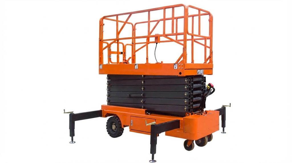
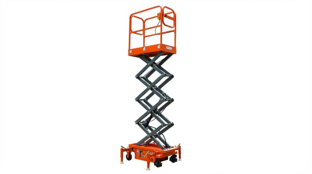
Scissor mechanisms raised the platform vertically, so horizontal reach primarily depended on deck size and extensions. PDW industrial tables used fixed platforms from 1.22 m × 0.91 m up to 3.05 m × 3.05 m, providing large working footprints but negligible outreach beyond the base. Rough-terrain lifts such as the HS1218ERT used a 2.97 m × 1.65 m deck with 0.65 m extensions, effectively increasing reach to access façades or racks without repositioning the chassis. Mini self-propelled units offered 1.63 m to 2.64 m long decks, 0.74 m to 1.12 m wide, with a consistent 0.9 m extension. That extension distance defined how far an operator could work beyond the wheelbase while staying within stability limits. Engineers considered both static reach and dynamic effects, since extended decks shifted the center of gravity and reduced residual stability margin.
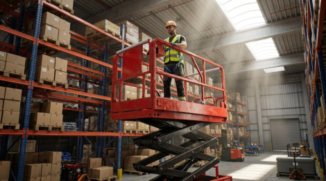
Indoor vs. Outdoor Working Height Constraints
Indoor and outdoor use imposed different practical limits on working height, even for identical platforms. Indoors, ceiling height, overhead services, and aisle width constrained the usable envelope more than wind or grade. PDW series lifts targeted indoor manufacturing, where short travel, high capacities up to about 4 350 kg, and compact footprints took priority over maximum elevation. Outdoors, wind, surface conditions, and slope governed safe height. Rough-terrain and mini self-propelled lifts with gradeability from 25 % to 30 % and ground clearances around 0.2 m operated on uneven ground but required derating in high winds. Standards and manuals restricted occupant count to one outdoors versus two indoors, and limited drive speed to below 0.8 km/h with the platform raised. Engineers therefore often selected a lower nominal working height for outdoor tasks than for comparable indoor work to preserve stability margins.
Standards And Rating Methods (ANSI, CE)
ANSI and CE standards defined how manufacturers determined and marked maximum height, reach, and load ratings. These frameworks required verification of platform capacity, including separate ratings for main deck and extension, such as 360 kg on the main platform and 113 kg on the extension for rough-terrain models. Test procedures validated that lifts met stability criteria at rated height under specified wind speeds and slopes, and that drive speed limits with raised platforms, often below 0.8 km/h, maintained control. Occupant limits followed standardized rules, typically two indoors and one outdoors, based on guardrail design, floor area, and evacuation considerations. Compliance labels, user manuals, and load charts reflected these standardized rating methods, allowing engineers and safety managers to compare different manufacturers’ products on a common, regulation-backed basis.
Engineering Factors Governing Height And Reach
Engineering limits on scissor lift height and reach depend on interacting structural, hydraulic, and control parameters. Designers needed to balance platform height, load, and mobility against stability envelopes defined by ANSI and CE standards. Real machines such as PDW industrial tables, mini self-propelled units, and rough‑terrain HS1218ERT illustrated how design choices changed allowable working height and reach. The following factors governed those limits in practice.
Structural Stability, Base Footprint, And Ground Conditions
Structural stability depended first on the relationship between base footprint and maximum platform height. Taller working heights required larger wheelbase dimensions, stronger scissor arms, and higher torsional stiffness to resist sway. Indoor PDW tables used wide base frames and high capacities but operated on flat, prepared floors, which reduced overturning risk. Self-propelled and rough‑terrain units relied on chassis geometry, tire contact area, and ground clearance to maintain stability on uneven ground. Operators had to keep lifts on firm, level surfaces because voids, soft soil, or un-compacted fill shifted reaction forces and reduced the available safety margin.
Load Capacity, Center Of Gravity, And Tipping Risk
Allowable platform capacity directly affected the system center of gravity (CoG) and tipping moment. PDW units carried up to 9 600 kilograms, but at relatively low heights, so the combined CoG remained close to the base plane. Self-propelled mini lifts typically carried 230–450 kilograms plus 113 kilograms on extensions, and HS1218ERT carried 360 kilograms plus 113 kilograms on its deck extension. These smaller loads were necessary because platform heights reached 12–13.7 meters. Standards required rating capacities for both retracted and elevated conditions and sometimes derated loads on extensions. Overloading, or concentrating mass at one guardrail, shifted the CoG toward the edge and could exceed the allowable overturning moment, especially outdoors, where wind and slope added lateral loads.
Actuation Systems, Drift, And Elevation Speed
Most scissor lifts used hydraulic actuation, often with electric drives for self-propelled machines. Cylinder bore, stroke, and system pressure set the available lifting force and therefore maximum rated load at height. Elevation speed had to balance productivity against dynamic loads; PDW raise times ranged from 20 seconds to 114 seconds, while mini scissor lifts ranged from 16/34 seconds to 80/60 seconds up/down. Faster motion increased inertial forces in the scissor stack and pins, which designers controlled using proportional valves and soft-start profiles. Hydraulic drift limited usable working height over time; quarterly drift tests at a fixed height under load verified that leakage in seals or valves stayed within specification. Maintenance practices such as fluid cleanliness, seal replacement every 3–5 years, and regular leak checks preserved the original height and reach performance.
Wind Loads, Gradeability, And Rough-Terrain Design
Wind and slope conditions significantly constrained safe working height, especially outdoors. Standards and manuals limited travel speed to about 0.8 kilometers per hour with the platform raised and restricted operation in high winds or thunderstorms. Rough‑terrain lifts such as HS1218ERT used four‑wheel drive, 0.2‑meter ground clearance, and specified gradeability to maintain traction and level support on uneven sites. Mini self‑propelled lifts offered 25–30% gradeability, but operators still had to elevate only on level, compacted surfaces. Increased ground clearance and tire diameter helped obstacle negotiation but raised the chassis CoG, so designers compensated with wider axles and heavier bases. Wind acting on guardrails, occupants, and materials created overturning moments that effectively reduced the allowable working height compared with indoor ratings, which explained why standards limited outdoor occupants to one person and often reduced maximum height in exposed conditions.
Selecting Scissor Lifts For Real-World Applications
Engineers selected scissor lifts by translating task geometry, environment, and load into quantitative height and reach requirements. They then mapped these requirements to platform height, working height, deck extension, and capacity envelopes defined by ANSI and CE ratings. Selection also required evaluation of terrain, duty cycle, and regulatory constraints, not just “maximum height” figures. The following subsections outlined a structured approach that reduced overspecification and mitigated safety risks.
Matching Height And Reach To Task Requirements
Height specification started from the work point, not the product brochure. Engineers defined the vertical distance from finished floor level to the highest task location, then subtracted a typical operator reach of about 2 m to estimate required platform height. For example, a 12 m platform height provided a 14 m working height, which aligned with HS1218ERT data. Horizontal reach depended on platform plan dimensions and extension length; a 0.65 m or 0.9 m deck extension allowed access over obstructions such as parapets or conveyors. Designers also considered approach constraints, including aisle width, turning radius, and doorway clearances, to ensure the lift could physically reach the work zone.
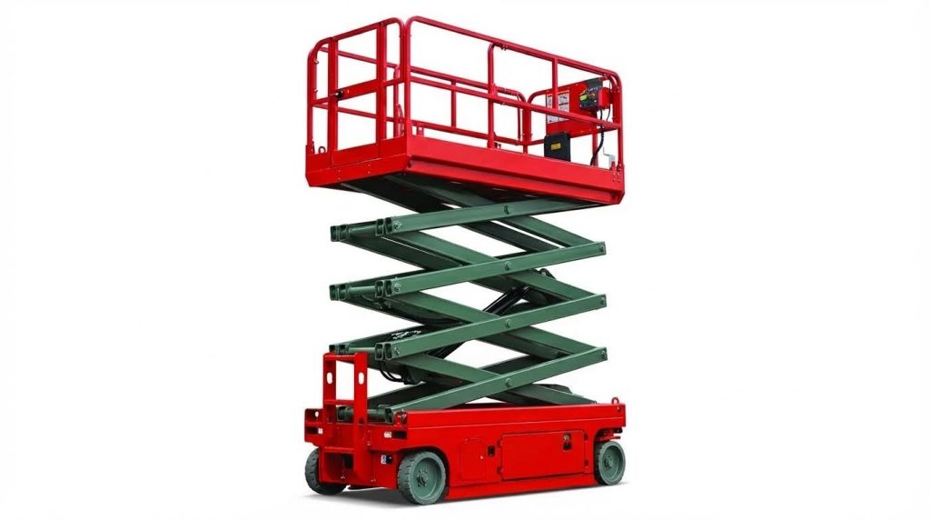
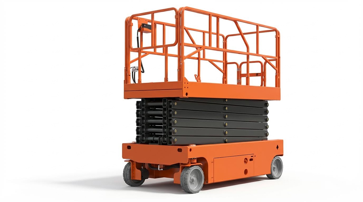
Comparing PDW, Mini, And Rough-Terrain Scissor Lifts
PDW Series lifts targeted fixed indoor manufacturing cells with high static loads. They offered platform heights from roughly 0.56 m to 1.47 m, raised heights up to about 1.78 m, and capacities between 3 200 lb and 9 600 lb, which suited pallet handling, assembly lines, and work-positioning. Self-propelled mini scissor lifts covered higher access tasks, with platform heights from 5.8 m to 13.7 m and working heights from 7.8 m to 15.7 m, plus 0.9 m extensions for increased reach. Rough-terrain models such as HS1218ERT provided 12 m platform height, 14 m working height, 0.65 m dual-side extensions, 0.2 m ground clearance, and four-wheel drive, which enabled outdoor and uneven-ground operation. Engineers compared these families using capacity, gradeability (25–30 % for minis), ground clearance, and mobility to align with either indoor flat-floor or mixed-terrain construction use cases.
Lifecycle Costs, Maintenance, And Predictive Analytics
Total cost of ownership often dominated selection decisions for fleets. Hydraulic systems required periodic fluid checks, with oil levels typically maintained 40–50 mm above tank bottoms at full extension. Seal and valve lifetimes of roughly 3–5 years, quarterly drift tests, and annual load tests influenced maintenance planning and downtime risk. Self-propelled lifts incurred additional costs for traction systems, batteries, and control electronics, but reduced manual handling and repositioning labor. Predictive analytics, fed by usage hours, elevation cycles, and drift trends, allowed maintenance teams to replace seals or adjust valves before major cylinder overhauls. This approach optimized lifecycle costs by avoiding unplanned outages and extending structural and hydraulic component life.
Digital Twins, Sensors, And Control System Integration
Modern scissor lifts increasingly integrated sensors, limit switches, and proportional control to manage height and reach within safe envelopes. Semiannual calibration of sensors and limit switches maintained correct stopping positions and prevented motor overloading at end-of-travel. Digital twins, built from design models and live telemetry, allowed engineers to simulate duty cycles, wind exposure, and grade conditions before deployment. Fleet managers combined digital inspection tools with onboard diagnostics to track drift, temperature, and vibration signatures, improving fault detection. Integration with site management systems supported automatic logging of ANSI and CE compliance checks, operator usage patterns, and alarm histories, which tightened feedback loops between real-world operation and future lift selection criteria.
Summary: Safe, Efficient Use Of Scissor Lift Height And Reach
Scissor lift height and reach performance depended on a tightly coupled set of geometric, structural, and control parameters. Manufacturers defined platform height, maximum working height, and horizontal reach through deck extensions, with typical working height margins of about 2 m above platform level for personnel. Across PDW, mini, and rough‑terrain models, rated capacities, platform dimensions, and elevation speeds established the safe operating envelope, while ANSI and CE standards constrained allowable occupants, ground slope, and wind conditions.
Industry practice had shifted toward application‑specific designs: high‑capacity, low‑stroke PDW tables for indoor manufacturing; compact self‑propelled mini lifts for constrained sites; and rough‑terrain units with higher ground clearance, four‑wheel drive, and 25–30% gradeability for outdoor work. This diversification improved productivity but required more rigorous selection, including verification of load cases, outreach needs, and site conditions. Future trends pointed to broader use of proportional controls, integrated sensors, and connected diagnostics to manage drift, monitor structural health, and enforce envelope limits in real time.
For practical implementation, engineers needed to treat maximum height and reach ratings as design limits, not targets to exceed. Site assessments, including ground bearing checks, slope, and wind exposure, remained essential before specifying lift class and model. Maintenance programs with documented hydraulic, structural, and electrical inspections supported both regulatory compliance and long‑term stability at height. A balanced view recognized that higher reach and capacity increased risk sensitivity: safe, efficient use depended less on absolute height and more on disciplined adherence to standards, accurate load assessment, and continuous monitoring of the machine’s working envelope.

