Scissor lift platforms covered in this guide ranged from compact hand-pushed tables to large rough-terrain machines. Engineers specified platform length, width, and vertical travel alongside base frame geometry and wheelbase to define the working envelope. Extension decks, rollers, and toe guards increased usable area but also altered load paths, deflection behavior, and stability margins. The full outline addressed core platform sizes and capacities, detailed extension design, and concluded with selection criteria, digital tools, and practical engineering recommendations for safe, standards-compliant deployment.
Core Platform Sizes And Capacity Ranges
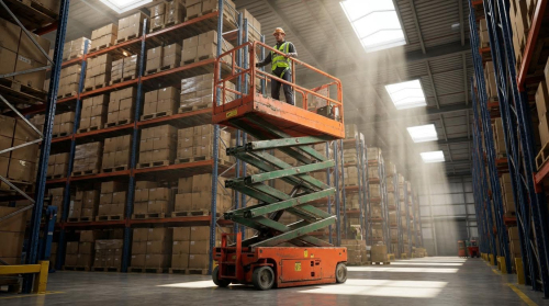
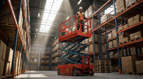
Core platform geometry and capacity defined the functional envelope of a scissor lift. Engineers balanced reach, footprint, and payload against stability and drive performance. Mobile work platforms typically operated in congested industrial and construction environments, so dimensional optimization directly affected productivity and risk. Understanding base platform sizes, extension effects, and regulatory usable area limits allowed robust specification and design.
Typical Platform Length, Width, And Height Envelopes
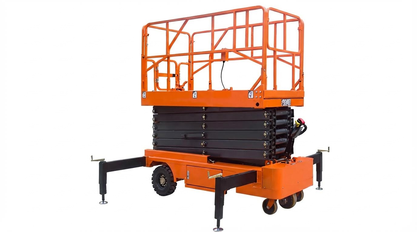
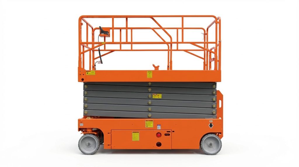
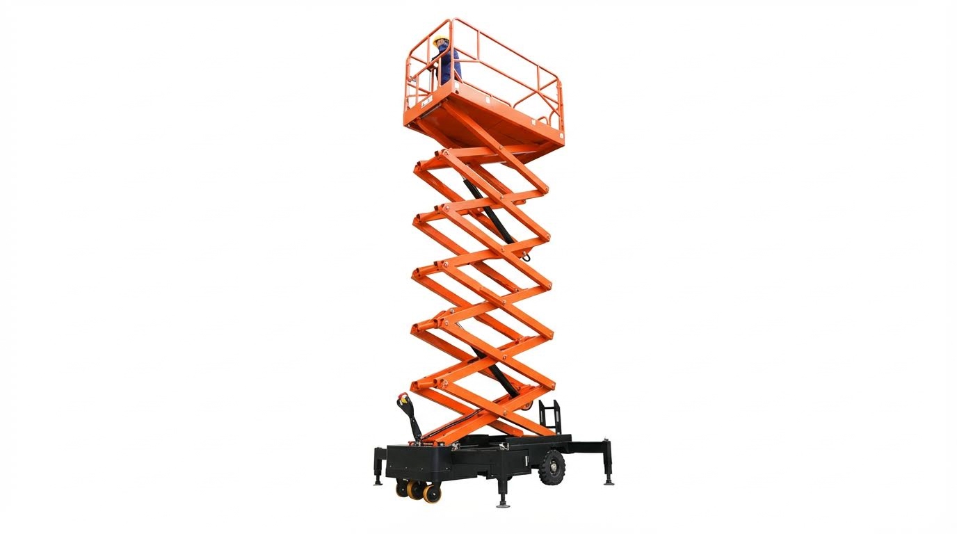
Mobile electric rough‑terrain platforms such as the HS5390 E PRO used platform lengths around 3.9 m, extendable to approximately 6.0 m with dual extensions. Platform widths around 1.9 m provided adequate lateral workspace while maintaining transport width near 2.3 m. Custom high‑altitude platforms from manufacturers like Shandong MRT offered work platform sizes up to about 2.64 m by 1.10 m with 0.9 m extension modules. Stationary industrial tables, for example Beacon BTSL units, used standard deck sizes from roughly 0.75 m × 1.07 m to 1.52 m × 3.05 m, with optional maximum platforms up to approximately 2.13 m × 3.66 m. Vertical travel envelopes ranged from low‑stroke tables with 0.5 m lift to high‑travel units exceeding 5.5 m, and aerial scissor lifts reached working heights between about 8 m and 18 m for typical electric models and up to roughly 18 m and above for diesel rough‑terrain variants.
Load Ratings: Base Platform Vs. Extension Capacity
Manufacturers always specified separate ratings for total platform load and extension‑zone load. For example, Haulotte scissor lifts covered payloads from about 150 kg to 750 kg, with the HS5390 E PRO rated around 750 kg total and roughly 225 kg on the extension deck. Electric compact models supported 350 kg at 8 m and 450 kg at 10 m working height, while larger rough‑terrain units reached about 750 kg at 18 m. Stationary scissor tables such as SJG series supported higher concentrated industrial loads, from 1,000 kg at 0.5 m stroke to 4,500 kg at 2.5 m stroke. Engineers had to ensure the sum of personnel, tools, and materials remained below the rated platform capacity and that localized loads on extensions respected the lower extension rating, which reflected higher bending moments and deflection at the cantilevered section.
Electric Vs. Diesel And Stationary Vs. Mobile Units
Electric mobile scissor lifts typically used narrower chassis and lower overall mass, which suited indoor applications in warehouses, malls, and hospitals. Their platforms still offered useful payloads, for instance 350–450 kg on compact machines and up to 750 kg on higher‑reach electric rough‑terrain models, while operating with low noise and zero local emissions. Diesel rough‑terrain units such as 13 m and 16 m models prioritized off‑road capability and higher ground clearance, often combining larger decks with robust frames and higher gradeability, around 25–40%. Stationary scissor tables, driven by electric motors in the 1.1–3.6 kW range, focused on high cycle life and heavy loads rather than mobility, so they accepted capacities up to 4,500 kg but operated over shorter vertical strokes. When selecting between these categories, engineers weighed duty cycle, travel distance, energy source availability, and indoor air quality constraints.
Standards, Guardrails, And Usable Work Area
Scissor lift platforms had to comply with regional standards such as CE and ISO requirements, along with OSHA and ANSI rules for design and use. These frameworks dictated minimum guardrail heights, toe‑board provisions, access gate design, and clear marking of rated capacities and permissible occupants. Optional beveled or straight toe guards, as used on industrial tables, increased plan dimensions slightly but improved edge protection and reduced trip risk
Engineering Design Of Platform Extensions
Extension Types: Slide-Out, Flip-Out, Dual And XL Decks
Engineers classified platform extensions by their deployment mechanism and target envelope. Slide-out decks translated linearly on rollers or sliding tubes and locked by pins or automatic latches. These designs maximized reach with minimal increase in stowed length and suited indoor electric scissors such as HS5390 E PRO or MRT series. Flip-out decks rotated about a hinge, providing compact storage and rapid deployment where overall transport length was constrained. Dual extensions combined front and rear or front and side decks to increase usable area and allow two work faces without repositioning the base machine. XL decks and “MAX” configurations increased both platform length and width, for example HS5390 E MAX with dual extensions and XL options, and required upgraded structures, cylinders, and stabilizing systems to maintain capacity and compliance with EN 280 or ANSI A92.
Structural Impacts Of Extensions On Stability
Extensions shifted the platform center of gravity outward relative to the scissor stack and chassis. This shift reduced longitudinal or lateral stability margins and decreased allowable side and longitudinal forces under standards. Manufacturers therefore derated extension capacities compared with the base deck, as seen on HS5390 E PRO with 1 654 lb base capacity and 496 lb extension rating. Structural design accounted for increased overturning moments by reinforcing scissor arms, pivot pins, and chassis outrigger or axle configurations. Engineers also controlled platform deflection under eccentric loads to keep rail heights and clearances within regulatory limits. Stability verification used worst-case combinations of maximum extension, rated load, maximum wind, and dynamic effects from braking or steering.
Load Distribution, Deflection, And Fatigue Considerations
Platform extensions introduced non-uniform load distributions, because workers and materials concentrated near the extended edge. Designers modeled the deck as a plate or grillage supported at the scissor interface and at extension guides, applying concentrated and line loads per code. They limited static deflection to maintain comfortable footing and avoid tripping at joints between base and extension segments. Repeated loading cycles at the extension interface created fatigue-critical details at welds, hinge pins, and roller tracks. Engineers therefore specified high-strength low-alloy steels, generous radii, and full-penetration welds in high-stress regions. Validation combined finite element analysis with strain-gauged prototype testing under accelerated duty cycles that represented construction, maintenance, and warehousing use patterns.
Integration With Rollers, Toe Guards, And Ergonomic Features
Extensions often integrated roller tops to support horizontal material transfer across the deck. Roller modules, such as hard-chromed roller tops, reduced push forces and minimized manual handling strain during loading and unloading. Engineers ensured roller frames did not compromise deck stiffness or introduce snag points at the extension joint. Toe guards and beveled edges, similar to optional guards on BTSL tables, mitigated shear and crush hazards in the lowered position and during travel. Electric toe-guard tape switches provided redundant protection by stopping motion on contact. Ergonomic features included low step-in heights, foldable handrails, and intuitive control panels mounted within reach at both base and extended positions. Designers verified that all added components preserved clear walkways, maintained required guardrail heights, and did not exceed allowable platform mass or affect drive and lift performance.
Selection Criteria For Platforms And Extensions
Matching Platform Envelope To Task And Facility Layout
Engineers first match platform length, width, and working height to the task geometry and access constraints. Indoor facilities like warehouses and hospitals typically required compact electric scissor lifts with narrow widths to pass through doors and aisles, for example 1.15 m to 1.32 m overall width in customized MRT units. Large construction sites benefitted from wide rough‑terrain platforms such as the HS5390 E PRO, with deck lengths extendable from about 3.9 m to 7.5 m to support multiple workers. The selected envelope must also consider turning radius, wheelbase, and stowed height to navigate ramps, mezzanines, and low overheads. Engineers often overlaid machine envelopes on facility CAD layouts to verify clearances at corners, columns, and loading zones.
Travel Distance, Duty Cycle, And Power Requirements
Travel distance and vertical cycling frequency strongly influenced powertrain and energy storage selection. High‑reach stationary lifts like Beacon BTSL platforms, with travel distances up to 4.6 m and raised heights to about 5.6 m, typically used fixed electric supplies such as 230 V single phase. Mobile units operating long horizontal distances in warehouses or yards required battery systems sized for daily duty cycles, for example 24 V packs in MRT models or 8 × 6 V, 435 Ah batteries in the HS5390 E PRO. Engineers estimated amp‑hour demand from lift cycles per hour, travel time, and auxiliary loads, then applied safety factors for cold environments and aging. Diesel rough‑terrain units suited outdoor, long‑range operation where on‑board fuel simplified refueling compared with frequent battery charging.
Safety Margins, Standards, And Maintenance Access
Selection criteria always incorporated regulatory requirements and conservative safety margins on load and stability. Designers and specifiers used rated capacities, such as 320 kg for MRT work platforms or 1 654 lb for HS5390 E PRO decks, then limited planned live loads to about 75–80% of rating to account for tools and dynamic effects. Compliance with CE and ISO standards or OSHA and ANSI guidance required guardrails, toe boards, interlocks, and clearly visible placards. Maintenance access also affected platform choice; stationary SJG units with accessible control boxes and documented inspection points simplified periodic structural and hydraulic checks. For mobile lifts, fold‑down guardrails, ground‑level diagnostic panels, and clear access to batteries and motors reduced downtime and supported documented inspection regimes.
Telematics, Predictive Maintenance, And Digital Twins
Advanced models used telematics and digital tools to optimize fleet selection and life‑cycle cost. Systems such as telematics on HS5390 E PRO transmitted usage hours, fault codes, battery status, and charging behavior, enabling data‑driven preventive maintenance. Engineers integrated these data with digital twins of the lift structure and hydraulic system to predict fatigue damage from real duty cycles rather than catalog assumptions. Fleet managers then adjusted inspection intervals, derated capacities for harsh environments, or reassigned machines based on predicted remaining life. During specification, availability of telematics, remote diagnostics, and open data interfaces became a criterion, especially for large industrial sites seeking to coordinate scissor lifts with broader asset management and safety monitoring platforms.
Summary And Practical Engineering Recommendations
Scissor lift platforms covered in this guide ranged from compact hand-pushed tables with 150 kg capacity to large rough-terrain machines lifting over 750 kg to heights above 18 m. Typical mobile work platforms operated with platform lengths around 3.5–6.0 m including extensions, widths near 1.1–1.9 m, and rated loads between 320 kg and 750 kg for indoor electric units, up to roughly 750–1000 kg for heavy-duty outdoor units. Stationary industrial tables demonstrated much higher capacities, up to 4.5 t, but at modest lift heights below 3 m. Electric units supported clean, low-noise indoor work, while diesel and rough-terrain variants addressed outdoor construction and maintenance.
From an industry perspective, increasing working heights, higher capacities, and longer dual or XL extensions expanded the usable work envelope but required tighter control of stability, deflection, and fatigue. Manufacturers integrated features such as dual extensions, roller tops, and ergonomic deck options to improve material handling throughput while maintaining compliance with CE, ISO, OSHA, and ANSI requirements. Future trends pointed toward higher energy density battery systems, integrated energy management, and advanced telematics that enabled predictive maintenance, remote diagnostics, and better fleet utilization analytics. Digital twins of platforms and extensions supported virtual validation of stability, load sharing, and structural life before physical prototyping.
For practical implementation, engineers should start with task analysis: required working height, horizontal reach via extensions, personnel count, tool and material mass, and facility constraints such as aisle width, door clearances, and floor bearing capacity. Select base platform dimensions and extension type so that rated capacity covers personnel plus tooling plus materials with a conservative margin, typically 20–30%, while respecting separate extension load ratings. Verify stability under worst-case conditions: fully extended deck, maximum side loading, and specified wind limits for outdoor work. Ensure guardrail geometry, toe boards, and optional toe guards preserve the usable work area without creating trip hazards or pinch points at the extension interface.
Finally, embed safety and maintainability in the specification. Require compliance with relevant EN, ISO, OSHA, and ANSI standards, and mandate documented pre-use inspections and periodic structural checks of arms, welds, pins, and hydraulic components. Favor platforms with accessible service points, clear diagnostic interfaces, and telematics for tracking duty cycles and overload events. Balance the desire for larger decks and longer extensions against maneuverability, total machine mass, and floor loads. This balanced approach allowed engineers to deploy scissor lift platforms and extensions that met productivity targets while maintaining long-term structural integrity and regulatory compliance.

