Safe and efficient operation of straddle stackers depends on understanding their core functions, operating limits, and control systems. This article explains key specifications, load centers, and pedestrian control principles, then walks through step-by-step procedures for loading, stacking, de-stacking, and travelling within the rated turning radius and speed range. It also details structured inspection, maintenance, and troubleshooting routines that align with typical 8-hour duty cycles and 200–600 hour service intervals. Finally, it summarizes best practices and training requirements so operators can handle counterbalanced stacker palletized loads at height with consistent safety and productivity using equipment such as Atomoving straddle stackers.
Core Functions And Operating Principles

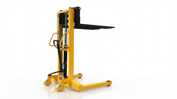
Straddle stackers operated as compact, powered lifting trucks for palletized loads in constrained aisles. They combined vertical lifting, short-distance transport, and precise stacking at moderate heights. Their design bridged the gap between manual pallet jack and full-size forklift trucks. Understanding specifications, stability principles, and pedestrian control logic remained essential for safe and efficient use.
Key Specifications And Load Limits
A typical electric straddle stacker had a maximum rated lifting capacity of 4 400 lb at the specified load center. The maximum lifting height reached approximately 118 in, which suited low to medium racking systems. Fork length usually measured 42 in, with a 22 in load center, meaning the rated capacity applied when the load’s center of gravity sat 22 in from the fork heel. Each fork often had an outer width near 6.5 in, allowing engagement with standard pallets while maintaining adequate section modulus and stiffness.
The maximum travel speed without load reached about 4.0 km/h and reduced to roughly 3.5 km/h at full load to preserve stability and stopping distance. The minimum turning radius around 41 in allowed operation in narrow aisles, but operators still needed to respect side clearances and pedestrian traffic. Although the nameplate capacity was 4 400 lb, recommended routine handling loads might be lower, for example about 1 543 lb, to maintain a conservative safety margin, especially at higher lift heights or in less ideal ground conditions. Overloading or partial loading was strictly prohibited because it increased the risk of structural overstress, mast deflection, and tipping.
Manufacturers required that loads did not project beyond the front section of the forks, which prevented excessive forward moment and fork tip overloading. Rated capacities assumed level, firm floors, correct tire condition, and fully functional brakes and hydraulics. Operators had to verify the data plate for capacity versus lift height and load center and then compare it with pallet weight and geometry before each lift. Adhering to these quantified limits aligned with applicable safety standards and reduced fatigue in structural welds and hydraulic components over the service life.
Stability, Load Center, And Fork Positioning
Straddle stacker stability depended on the relationship between the combined center of gravity of truck and load and the support polygon formed by the drive wheel and load wheels. The specified 22 in load center defined the horizontal distance from the fork heel to the nominal center of gravity of a uniformly distributed pallet load. When a load extended beyond this distance, the effective load center increased, which reduced the residual capacity and moved the combined center of gravity closer to the front stability boundary. This effect became more critical as lift height increased because the elevated mass produced a larger overturning moment around the front axle line.
Correct fork positioning minimized these risks. Operators had to insert the forks fully under the pallet so that the pallet deck boards rested completely on the fork blades. The load could not overhang the fork tips because that shifted the center of gravity forward and concentrated bending stress at the fork heel. Fork height during travel remained low, typically just clear of the floor, which lowered the center of gravity and improved lateral stability during turning.
During loading and stacking, the operator positioned the truck square to the pallet or rack, raised the forks to just below the pallet underside, then advanced until the pallet sat fully supported. For stacking at height, the lift occurred with the truck stationary, followed by careful inching forward to place the pallet onto the shelf. Lowering proceeded slowly to transfer weight to the rack before withdrawing the forks. Maintaining vertical mast alignment, avoiding sudden steering inputs, and respecting the rated load-height diagram were central to maintaining the stability margin.
Pedestrian Control, Tiller Zones, And Braking
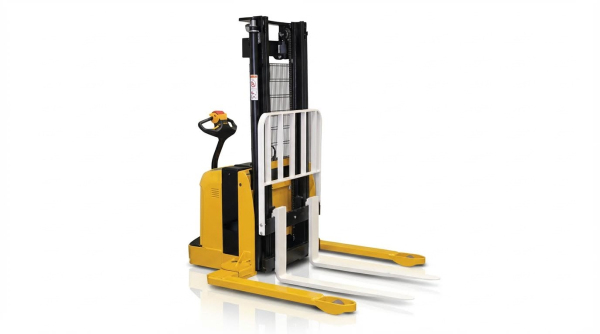
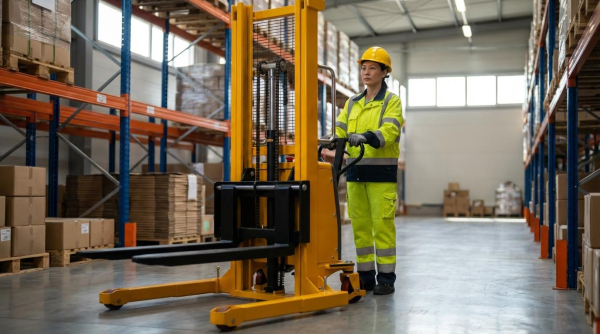
Pedestrian-operated straddle stackers typically used a tiller arm as the primary control interface. The operator walked ahead or alongside the truck, using the tiller to command travel direction, speed, lifting, and lowering. Control logic generally linked travel authorization to the tiller angle, with defined operating zones that balanced maneuverability and safety. At low speeds, this configuration allowed precise positioning in tight rack aisles and loading docks.
Tiller zones A and B defined angular ranges where the brake released and traction drive engaged. Weekly checks required moving the tiller between these zones and confirming an audible clicking sound from the brake mechanism. Correct brake clearance, typically about 0.2–0.8 mm (0.00787–0.0315 in), ensured that the brake applied fully when the tiller moved to the upright or fully lowered parking position, yet released cleanly during travel. Excessive clearance reduced braking torque, while insufficient clearance caused drag, overheating, and premature wear.
Braking functions included service braking through the traction controller and mechanical or electromagnetic parking braking. Releasing the tiller to its neutral or vertical position automatically engaged the brake for fail-safe stopping. Operators learned to modulate speed using the travel control and to avoid abrupt reversals that could destabilize a loaded mast. Regular inspection of the tiller pivot, linkage, micro-switches, and brake components ensured that the control zones remained well defined, the clicking feedback remained audible, and the truck stopped predictably under all permitted operating conditions.
Step-By-Step Operating Procedures
Structured operating procedures reduced incident rates and improved equipment utilization in industrial environments. Straddle stacker operators followed defined steps from pre-use checks through travel and stacking tasks. Each phase required correct speed control, fork positioning, and load handling discipline. The following sub-sections described practical, field-tested procedures that aligned with typical manufacturer recommendations and safety standards.
Pre-Operation Safety And Area Checks
Operators first performed a walk-around inspection before energizing the straddle stacker. They checked forks, mast, lift chains, wheels, and hydraulic components for cracks, leaks, or deformation. They verified that warning devices, horn, emergency stop, and safety kickback switches functioned correctly. The operator inspected the battery charge level and confirmed that cables, plugs, and connectors showed no visible damage.
The work area then required a systematic survey. Operators ensured the floor surface was level, clean, and free from oil, loose materials, or obstacles. They confirmed that aisles, turning zones, and racking fronts provided sufficient clearance for the 41 inch minimum turning radius. Overhead obstructions, sprinklers, and lighting fixtures had to clear the planned lifting height with margin.
Traffic management formed part of the pre-operation check. Pedestrian routes and other vehicle paths needed clear demarcation. Operators confirmed that stacking locations could support the imposed loads and that pallets were structurally sound. If any defect or unsafe condition appeared, the stacker remained out of service until maintenance personnel resolved the issue.
Loading Pallets Onto The Straddle Stacker
Operators approached the load in a straight line at low speed. They aligned the 42 inch forks with the pallet openings and ensured the straddle legs cleared the pallet footprint. Before entry, they set the fork height just below the pallet bottom to avoid dragging or impact. The goods could not project beyond the front section of each fork to maintain stability.
With the stacker aligned, the operator moved forward until the forks fully supported the load at the 22 inch load center. It was strictly forbidden to overload or partially load the stacker, even if the rated maximum capacity was 4400 pounds. For routine handling, recommended practice limited fork lift loads to approximately 1543 pounds to preserve stability and component life. The operator then lifted the pallet just high enough to clear the floor, minimizing the center-of-gravity elevation.
After lifting, the operator reversed slowly with the load, maintaining forks low and mast vertical. Sudden acceleration, harsh braking, or sharp steering inputs were avoided to reduce dynamic load shifts. The operator kept the load facing the primary travel direction where possible, improving visibility and control. At all times, pedestrians were kept clear of the load path and potential crush zones around the straddle legs.
Stacking And De-Stacking At Height
For stacking, the operator travelled with the load lowered until near the racking position. At the front of the target shelf, they stopped and checked that the structure and pallet could support the intended mass. The operator then raised the load to slightly above the final placement height while stationary, avoiding lift operations during travel. Visibility of fork tips and pallet edges remained critical during this phase.
Once the load reached the correct height, the operator inched the stacker forward until the pallet sat fully over the shelf beams. They then lowered the forks slowly so that the pallet bottom seated evenly on the shelf surface. As the weight transferred from forks to rack, the operator monitored for tilting, misalignment, or abnormal noises. When the pallet rested securely, they reversed carefully to withdraw the forks without contact.
De-stacking followed the reverse sequence. The operator aligned at shelf level, inserted forks completely under the pallet, and lifted until clear of the beams. They then reversed slowly to bring the load clear of the rack before lowering to a safe travel height. Throughout stacking and de-stacking, operators maintained low speed, smooth hydraulic inputs, and strict adherence to rated lift height and capacity.
Travel, Turning Radius, And Speed Control
Travel procedures prioritized stability and predictable machine behavior. Operators set travel speed according to floor condition, congestion, and load mass. The stacker’s maximum speed without load was 4.0 kilometers per hour, while with full load it reduced to 3.5 kilometers per hour. In practice, operators often used lower speeds in confined aisles or near pedestrians.
The 41 inch minimum turning radius required careful planning in narrow aisles and at rack ends. Operators avoided full-lock steering with elevated loads because tight turns increased lateral forces on the mast and forks. They kept forks as low as practicable during travel to reduce overturning moments. Sudden changes in direction or emergency braking with raised loads were avoided unless collision risk existed.
Speed control relied on progressive tiller inputs and awareness of braking distance. Operators tested the service brake and any regenerative or electromagnetic braking function during pre-use checks. In operation, they anticipated stops well ahead of intersections and doorways. When visibility was restricted, operators reduced speed, used the horn, and, if necessary, employed a trained banksman to guide movements.
On ramps or uneven surfaces, operators followed site rules that often prohibited elevated travel. They kept the load upgrade where slopes existed and avoided lateral travel across gradients. By combining adherence to the specified speeds, turning radius limits, and conservative fork heights, operators maintained safe, efficient movement of loads throughout the facility.
Inspection, Maintenance, And Troubleshooting

Structured inspection and maintenance of straddle stackers reduced failures and extended service life. Maintenance regimes historically referenced an 8-hour duty day and approximately 200 operating hours per month. This section detailed time-based inspection tasks, subsystem maintenance, and systematic troubleshooting. It supported safe operation, regulatory compliance, and predictable lifecycle cost control.
Daily, Weekly, And Monthly Inspection Tasks
Daily inspections focused on basic safety and fluid levels. Operators lowered the forks fully, then checked hydraulic oil level against the specified grade for the installed mast height. They verified battery charge status against the battery maintenance instructions and looked for visible leaks, cracks, or loose components on mast, forks, chains, hoses, wheels, and chassis. Daily checks also included control function tests, brakes, horn, steering response, and emergency devices.
Weekly inspections occurred at roughly 50 operating hours. Technicians checked brake function by switching the tiller between zones A and B and confirming an audible clicking sound. They measured brake clearance and maintained it between 0.00787 inches and 0.0315 inches. Weekly tasks included cleaning steering gear surfaces, removing oil and dust, and inspecting wheels and rollers for flat spots or damage. Battery electrolyte levels were checked and topped up with purified water, and batteries were cleaned externally after sealing the caps.
Monthly inspections aligned with 200 operating hours. These checks repeated daily and weekly items, while adding structural and functional verification. Personnel inspected the chassis for cracks, checked tiller flexibility, and confirmed horn and all safety interlocks operated correctly. Brake clearance was verified in metric units at 0.2–0.8 millimetres. Inspectors examined linkages, forks, mast rollers, lift chains, cylinders, and oil hoses for deformation, cracks, leakage, or lubrication needs. Electrical harnesses, fuses, and connectors were also visually checked for damage or looseness.
Hydraulic, Battery, And Brake Maintenance
Hydraulic maintenance relied on correct oil quantity and grade. The required hydraulic oil volume depended on maximum lift height: 5 litres for 2.5 metres, 5.5 litres for 3.0 metres, 5.7 litres for 3.3 metres, and 6 litres for 3.5 metres. Maintenance staff inspected cylinders, hoses, and fittings for leaks and replaced worn seals to prevent internal bypass, which could cause slow or uneven lifting. They also monitored mast and chain lubrication to reduce friction and maintain smooth vertical motion.
Battery maintenance combined charge management and electrolyte control. Operators checked charge level daily and avoided deep discharge to limit capacity loss. Weekly, they inspected electrolyte level and restored it with purified water when low. After a full charge, they confirmed electrolyte specific gravity around 10.67 pounds per gallon, indicating correct state of charge. External battery surfaces were washed with tap water only after caps were sealed, preventing contamination of cells and corrosion of terminals.
Brake maintenance ensured consistent stopping distance and parking security. Weekly and monthly checks verified brake clearance remained within the specified ranges. Technicians tested service brakes for adequate travel and holding force and confirmed the emergency set brake and safety kickback switches operated correctly. Quarterly, they cleaned brake pads, inspected lining wear, and checked return springs and linkages for free movement. Any contamination with oil or grease required immediate cleaning and root-cause investigation of the leak source.
Electrical System Checks And Adjustments
Electrical inspections covered power distribution, control circuits, and drive components. Monthly and quarterly checks included verifying plug integrity, key switch function, and operation of contactors and micro-switches. Technicians inspected wiring harnesses for insulation damage, abrasion points, and loose terminals. They measured contactor surface condition and removed light pitting with fine sandpaper, replacing components that showed excessive wear or malfunction.
Motor condition significantly influenced performance and reliability. Maintenance personnel assessed traction and pump motors for brush wear and commutator surface quality. Excessive sparking or uneven commutator bands indicated the need for brush replacement or machining. They confirmed fuses matched specified ratings and were free from heat damage or deformation. Battery discharge indicators, lift and travel controls, and safety interlocks were function-tested under load to ensure correct response and fail-safe behaviour.
Adjustments followed manufacturer tolerances and documented procedures. After any electrical repair, technicians performed functional tests for lift, lower, travel, and braking at low speed in a controlled area. They verified that safety devices, including emergency stops and kickback switches, interrupted power as designed. All findings, parts replacements, and parameter changes were recorded to support trend analysis and future troubleshooting.
Common Faults, Root Causes, And Corrections
Lift failure represented a frequent fault category. Forks could not rise due to overload relative to rated capacity, low overflow valve pressure, internal cylinder leakage, insufficient hydraulic oil, or inadequate battery voltage. Incorrect control handle position, a damaged oil pump motor, a defective pump, or a failed lift button switch also caused non-lifting conditions. Corrective actions included reducing load, adjusting relief pressure, replacing cylinder seals, topping up hydraulic oil, charging or replacing batteries, and repairing or replacing faulty electrical and hydraulic components.
Performance degradation often appeared as slow or uneven lifting and abnormal noise. Low hydraulic fluid level, aerated oil, worn pump elements, or partially blocked filters caused slow operation. Uneven lifting indicated cylinder bypass, chain tension imbalance, or mast roller binding. Technicians bled the hydraulic system, replaced contaminated oil, adjusted chains, and replaced damaged rollers. Any abnormal mechanical noise triggered immediate inspection of bearings, gears, and structural members for wear or cracking.
Control-related faults included unresponsive travel, unexpected stopping, or intermittent operation. Loose wiring, damaged micro-switches, degraded contactors, or faulty controllers typically caused these symptoms. Systematic troubleshooting started with visual inspection, then progressed to continuity checks and voltage measurements against wiring diagrams. When faults or leaks were detected, operators removed the lift stacker from service and generated a detailed work order specifying symptoms, test results, and required repairs. This disciplined approach reduced recurrence and supported long-term reliability.
Summary Of Best Practices And Training Needs
Safe and efficient straddle stacker operation depended on strict adherence to load limits, correct fork positioning, and disciplined driving practices. Operators had to respect rated capacities, recommended working loads, and load center distances to avoid structural overload and loss of stability. Consistent use of pre-operation checks, controlled lifting and lowering sequences, and compliance with turning radius and speed limits reduced collision and tip-over risk in confined aisles. Systematic inspection and maintenance, aligned with operating hours, extended component life and minimized unplanned downtime.
Industry practice increasingly tied equipment safety to formal operator training and documented competency. Structured courses for straddle stackers covered pedestrian control, tiller zones, braking behavior, and height-related stacking techniques. Training providers differentiated course length for novice, experienced, and refresher candidates, which allowed tailored progression and better skill retention. Organizations integrated this training with written procedures, visual load charts, and standardized checklists to build a repeatable safety culture.
Practical implementation required matching counterbalanced stacker specifications to the application envelope, including aisle width, racking heights, pallet types, and duty cycles. Maintenance planning used operating-hour based intervals for hydraulic, electrical, and mechanical systems, with clear responsibilities between operators and technicians. Digital maintenance logs and fault reporting workflows improved traceability and regulatory compliance. Future developments pointed toward enhanced diagnostics, interlocks, and possibly telematics-based monitoring, but core principles remained unchanged: trained operators, correct loading, and disciplined inspection routines formed the foundation of safe straddle stacker use.