Straddle stackers played a central role in high-density warehouse storage, order picking, and pallet handling. This article examined their core functions, how they differed from pallet jacks, and how stability principles governed safe operation. It then explored precision fork control, mast dynamics, and safety mechanisms that reduced risks such as tip-over, run-over, and falling loads. Finally, it reviewed drive, hydraulic, and electronic control systems that enabled accurate, energy-efficient, and reliable fork positioning in demanding warehouse environments.
Core Functions Of Straddle Stackers In Warehouses
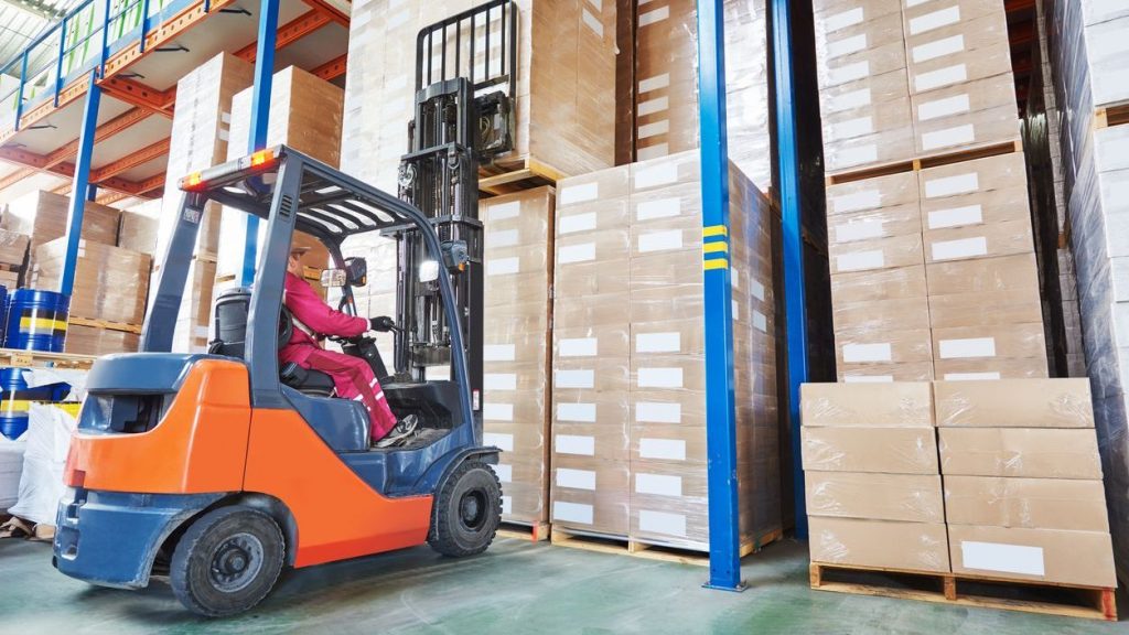
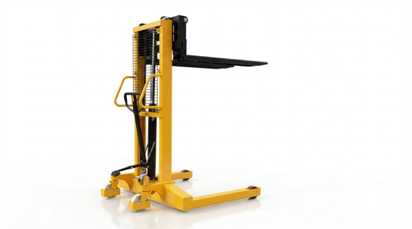
Straddle stackers operated as core assets in dense warehouse and distribution environments. They combined vertical lifting, horizontal transport, and precise fork positioning in a compact chassis. Their straddle legs allowed operators to handle palletized and non-standard loads without needing wide aisles. As a result, facilities used them to bridge the gap between pallet jacks and counterbalanced stacker.
Straddle Versus Pallet Jacks: Functional Differences
Straddle stackers differed from pallet jacks primarily in lift height, stability concept, and control sophistication. Pallet jacks moved loads at floor level or with minimal lift, while straddle stackers reached fork heights up to roughly 3.0 m to 3.5 m. Stackers used mast structures, straddle legs, and counterbalancing geometry to keep elevated loads stable, rather than relying only on pallet engagement. They typically featured powered lift, powered travel, electronic power steering, and multi-function tiller heads, whereas pallet jacks often used manual pumping and simple directional controls. These differences made straddle stackers suitable for racking, staging, and trailer work in narrow aisles where conventional forklifts could not operate efficiently.
Stability Triangle, Load Moment, And Straddle Legs
Engineers applied the stability triangle and load moment concepts to straddle stacker design and operation. The wheel contact points formed a polygon that defined the stability region; the combined center of gravity of truck and load had to remain within this region during travel and lifting. Straddle legs widened the effective base and moved the stability boundary outward, especially in the lateral direction. Operators maintained safety by keeping the load centered on the forks, respecting the rated load center on the data plate, and avoiding side loading that shifted the center of gravity toward an edge of the stability triangle. Understanding how mast tilt, fork height, and acceleration altered load moment helped reduce tip-over risks during tight maneuvers and ramp operations.
Typical Capacities, Lift Heights, And Duty Cycles
Modern walkie-type straddle stackers typically carried rated capacities between 1 360 kg and 1 800 kg. Maximum fork heights often ranged from about 2 700 mm to 3 000 mm, with some heavy-duty models reaching approximately 3 000 mm or slightly higher. Lifting speeds up to about 5.4 m/min supported efficient stacking while still allowing controlled handling of fragile loads, especially when combined with soft-landing functions near floor level. Duty cycles depended on battery capacity, three-phase AC drive efficiency, and regenerative braking performance, with 24 V systems supporting extended shifts under moderate load factors. Specifying duty class correctly required analysis of lift frequency per hour, average load mass, travel distance, and ambient conditions, including freezer or high-temperature environments.
Matching Stackers To Aisle Widths And Applications
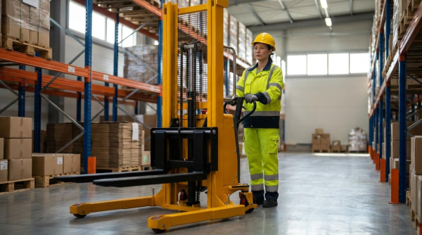
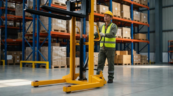
Warehouse planners matched straddle stackers to aisle widths by considering truck length, turning radius, and required right-angle stacking clearance. Compact chassis designs and electronic steering allowed operation in narrow aisles where counterbalance trucks would require significantly more space. Crawl-speed and pinwheel functions enabled operators to rotate the truck within confined zones, such as inside trailers or between closely spaced racks. Application selection also considered floor quality, load type, and required lift height; straddle legs needed compatible pallet openings or load supports to avoid interference. Facilities handling mixed pallet sizes, stillages, or partial loads often favored straddle stackers for their ability to straddle loads and place forks under a wide range of platforms without relying solely on standardized pallet entry dimensions.
Fork Control, Load Handling, And Safety Mechanics
Fork control defined how precisely operators positioned, lifted, and transported loads. Straddle stackers relied on coordinated mechanical, hydraulic, and electronic systems to keep loads stable during these tasks. Safety mechanics integrated speed control, braking logic, and interlocks to reduce incident risk. Effective operation required operators to understand both the physical load behavior and the machine’s built-in protection functions.
Fork Positioning, Levelness, And Load Center Control
Accurate fork positioning started with aligning fork height and spacing to the pallet openings before entry. Operators kept both fork tips in the same plane to avoid twisting the pallet or shifting the center of gravity. Level forks maintained a predictable load center, typically at 500 mm from the fork heel for standardized pallets. Misalignment created uneven load moments that increased mast side loading and reduced stability margins.
Maintaining fork levelness during travel prevented gradual load creep toward one side. Electronic tilt and lift controls, combined with rigid mast guidance, supported consistent fork geometry under load. Operators centered the load laterally between the straddle legs and kept the heaviest side against the carriage or backrest. This practice reduced the overturning moment and kept the combined center of gravity within the stability triangle.
Good load center control also depended on correct fork length selection. Forks extended to at least 75% of the load length to prevent nose diving or pallet breakage. Overhanging loads were minimized, especially at upper rack levels, where small shifts produced large changes in overturning moment. Operators verified actual load mass against the data plate limits before lifting to full height.
Mast Lifting Profiles, Soft Landing, And Fragile Loads
Mast lifting profiles described how lift speed and acceleration changed over the stroke. Modern straddle stackers used proportional hydraulic valves to deliver smooth ramp-up and ramp-down of lift speed. Typical lifting speeds of about 5.4 m/min supported efficient stacking while limiting dynamic shock to the load and mast. The control system maintained consistent speed under varying loads by regulating hydraulic pressure and flow.
Soft landing functions protected fragile loads during lowering. When forks approached approximately 100 mm above the floor, the control system reduced lowering speed automatically. This reduction limited impact energy when the pallet contacted the ground or rack beams. It also reduced transmitted shock into hydraulic components and fork structures, extending component life.
Fragile loads such as glass, electronics, or loosely packed cartons required even more controlled mast movement. Operators combined low lift and lower speeds with minimal travel speed when elevated. Single-cylinder mast designs improved forward visibility, which helped operators place forks precisely onto rack beams without striking packages. Using load backrests and correct pallet types further reduced the risk of product displacement during vertical movements.
Automatic Speed Reduction And Brake Override Logic
Automatic speed reduction systems linked travel speed to mast height and steering angle. When forks rose above predefined thresholds, the controller reduced maximum travel speed to limit kinetic energy and tipping risk. Additional speed reduction occurred at high steering angles, improving control during tight turns in narrow aisles. These measures kept the combined center of gravity within safe limits during dynamic maneuvers.
Brake override logic supported maneuvering in constrained spaces such as trailers or very narrow aisles. With the tiller or steering handle in a near-vertical position, operators could command low-speed travel while conventional braking inputs were partially overridden. This logic allowed the machine to pivot, or “pinwheel,” around the drive wheel without losing control authority. Safety algorithms still monitored direction commands and emergency stop inputs to prevent unintended motion.
Multi-stage braking systems integrated release braking, reverse braking, and emergency braking. Release braking activated when the operator released the travel control, using regenerative or electric braking before mechanical brakes applied. Reverse braking engaged when the direction command changed, controlling deceleration rates to avoid load shift. Large emergency stop or belly buttons provided immediate power cut-off and braking when pressed.
Preventing Tip-Over, Run-Over, And Falling Load Incidents
Tip-over prevention relied on understanding the stability triangle and keeping the combined center of gravity inside it. Operators avoided sharp turns at elevated fork heights and respected rated capacities at specific lift heights shown on the data plate. Straddle legs widened the support base, but improper load placement or off-center pallets still increased overturning moments. Automatic speed reduction and controlled acceleration further reduced lateral and longitudinal instability.
Run-over incidents typically involved pedestrians or the operator’s own feet in walk-behind modes. Clear aisle markings, horn use at intersections, and strict pedestrian exclusion zones reduced collision risk. Emergency reversing buttons on the tiller head reversed travel direction or stopped the truck if the operator became pinned. Good visibility from the mast design and adequate lighting also supported early hazard detection.
Falling load incidents often traced back to poor fork insertion, damaged pallets, or incorrect stacking patterns. Operators inserted forks fully under the load, verified pallet integrity, and used load backrests where available. They avoided lifting skewed or loosely wrapped loads to high levels without reconfiguring or stabilizing them. Regular inspection of forks, mast chains, and carriage components ensured structural integrity, minimizing the chance of sudden mechanical failures that could drop a load.
Drive, Hydraulic, And Control Systems Engineering
Drive, hydraulic, and control systems defined the performance envelope of modern straddle stackers. Engineers integrated three‑phase AC traction, closed hydraulic circuits, and networked controllers to balance precision, safety, and efficiency. Understanding interactions between these subsystems helped operators and maintenance teams prevent failures and extend service life. This section examined key engineering aspects that governed reliability, energy use, and fork control accuracy.
Three-Phase AC Drives, Regenerative Braking, And Energy Use
Three‑phase AC drive motors delivered high torque at low speeds and smooth acceleration for walk‑behind counterbalanced stacker. These motors operated with brushless construction, which eliminated brush wear and reduced routine maintenance. Typical systems ran on 24 V battery packs sized for warehouse duty cycles, with current controlled by dedicated AC inverters. Engineers selected motor and controller ratings to handle continuous travel plus short overloads during ramp starts and dock transitions.
Regenerative braking captured kinetic energy during deceleration and grade descent and returned it to the battery. This function reduced friction brake use, limited heat generation, and extended component life. Control logic monitored travel speed and direction, then modulated regeneration to avoid wheel lock and sliding on inclines. In high‑throughput operations, energy recovered through regeneration measurably extended operating time between charges.
Drive controllers also implemented automatic speed reduction when forks reached defined lift heights or when steering angle exceeded calibrated thresholds. This strategy lowered kinetic energy during high‑risk maneuvers and helped maintain stability margins. Crawl‑speed and pinwheel functions allowed precise positioning in tight aisles while keeping current draw within safe limits. Engineers validated these behaviors using load‑case simulations that combined mass, gradient, and friction coefficients.
Hydraulic Integrity, Oil Management, And Heat Control
Hydraulic systems powered mast lifting, lowering, and fine fork positioning, so fluid integrity directly affected safety. Routine inspections checked cylinders for abnormal noise and visible leakage around rods, seals, and ports. Technicians examined hoses and fittings for abrasion, cracks, or sweating, then tightened joints carefully to avoid deformation that could worsen leaks. Oil levels stayed near the upper mark on the sight gauge or vernier to prevent aeration and cavitation.
Hydraulic oil required periodic replacement, typically after about six months or 1 500 operating hours, whichever occurred first. Samples taken from tank bottoms revealed contamination levels; yellow ring patterns indicated mild pollution, while dark particulates signaled severe contamination. In the latter case, maintenance teams replaced oil and filters and flushed affected lines. Mixing different oil brands or viscosities was avoided because it changed additive performance and could destabilize seals.
Operators monitored system temperature using built‑in thermometers or infrared tools, targeting roughly 43–60 °C (110–140 °F). Temperatures above this range prompted checks of oil quantity, cooler function, and relief‑valve settings to limit excessive pressure drop. White or foamy oil after operation suggested air entrainment, often from low fluid levels or suction leaks at pump inlets. High‑pitched pump noise indicated cavitation or blocked suction filters, which required immediate cleaning or replacement.
Fork Structural Inspection, Wear Limits, And NDT Practices
Fork structures carried cyclic bending loads, so systematic inspection prevented brittle failures and sudden collapses. Technicians evaluated fork arms and blades for visible cracks, permanent bends, and angle deviations between blade and shank. If the angle exceeded approximately 90° or showed clear deformation, engineers specified repair or replacement. The upper planes of both forks needed to remain in a common plane under load to ensure symmetric load sharing.
Dimensional checks covered fork length, tip offset, and wear at contact surfaces. A level difference greater than 5 mm between fork tips or a length difference above 10 mm indicated unacceptable asymmetry. Wear reducing fork length by more than 40 mm from the nominal dimension triggered replacement decisions. Clamping iron openings on upper and lower fork interfaces typically had a 27 mm nominal and a 29 mm use limit; exceeding this range required adjustment or renewal.
Roller diameters provided another wear indicator, with main rollers limited to 0.1 mm diameter loss and side rollers to 0.5 mm. Exceeding these values changed load paths and increased local stresses in the mast channel. Non‑destructive testing, such as magnetic particle or dye penetrant inspection, targeted stress‑bearing areas on yokes, weld toes, and fork surfaces. Any crack indications at welds or in the protective frame, including deformations above about 2 mm, demanded reshaping, re‑welding, or component replacement.
Electronic Controllers, CANBUS, And Fault Diagnostics
Electronic control units coordinated traction, hydraulics, and safety interlocks through integrated software. AC controllers, such as those using vector control strategies, regulated motor torque, speed, and regenerative braking with high resolution. These units processed inputs from travel switches, lift commands, steering encoders, and height sensors. Safety functions, including emergency stop, emergency reverse, and automatic speed reduction, operated through redundant logic paths.
CANBUS communication architectures linked controllers, sensors, and actuators using a robust differential bus. This topology reduced wiring complexity and improved noise immunity in electrically harsh warehouse environments. High‑priority messages, such as emergency shutdowns or fault flags, pre‑empted non‑critical traffic to ensure rapid response. Engineers configured node identifiers and baud rates to match required update speeds for travel, steering, and lift subsystems.
Diagnostic capabilities relied on onboard fault codes, data logging, and external service tools. Controllers stored error histories for events like overcurrent, overtemperature, sensor loss, or communication timeouts. Technicians accessed this data via display panels or service ports to guide troubleshooting and component replacement. Abnormal temperatures in servo valves above roughly 65 °C (150 °F) or hot spots on electric motors triggered lockout and tag‑out procedures until root causes, such as contamination or bearing damage, were resolved.
Summary: Safe, Efficient Straddle Stacker Fork Control
Safe, efficient fork control on straddle stackers relied on the tight integration of mechanics, hydraulics, electronics, and operator practice. Core functions such as narrow-aisle maneuvering, stable straddling around pallets, and precise vertical positioning demanded accurate understanding of load moment, stability triangles, and rated capacities. Typical warehouse units operated with capacities between 1 360 kg and 1 800 kg and lift heights near 3 m, so respecting the data plate and keeping loads centered at the specified load center remained critical to prevent tip-over and falling loads.
Advanced fork and mast control technologies increased both productivity and protection of goods. Soft-landing mast profiles that slowed forks in the last 100 mm to 120 mm of travel reduced impact on fragile loads and racking. Automatic speed reduction with elevated forks or large steering angles, combined with brake override for very tight turns, supported controlled travel in confined aisles and trailers. Three-phase AC drives, electronic power steering, and regenerative braking improved energy efficiency and reduced operator fatigue, while multi-function tillers and crawl-speed modes enabled precise pinwheeling in congested areas.
From an engineering perspective, long-term safety depended on rigorous hydraulic and structural integrity. Scheduled oil changes, contamination monitoring, temperature control between roughly 43 °C and 60 °C, and prompt response to cavitation or aeration indicators protected pumps and valves. Defined fork wear limits, angle tolerances, and non-destructive testing of yokes, welds, and protective frames ensured that forks maintained geometric accuracy and load-bearing capability. Electronic controllers and CANBUS architectures allowed stable torque control, coordinated braking, and fast fault diagnostics, but required disciplined lockout–tagout and parameter management.
Looking ahead, straddle stackers would increasingly combine higher-efficiency AC drives, smarter mast and fork motion profiles, and richer sensor feedback. Expect closer integration with warehouse management and safety systems, including geo-fenced speed limits and enhanced pedestrian awareness technologies. However, even as control systems grew more intelligent, the fundamentals stayed the same: operators needed training on stability and load placement, maintenance teams needed clear inspection criteria and intervals, and managers needed to align equipment selection with aisle geometry and duty cycles. Balancing these elements allowed facilities to extract maximum throughput while maintaining a defensible safety margin around every lift and travel operation.