Straddle stacker steering design determined how precisely operators could position loads in narrow warehouse aisles, on ramps, and near racking. This article examined which wheels actually steered a straddle stacker, how drive wheels, load wheels, and casters shared forces, and how the straddle legs and stability triangle controlled tip-over risk. It then analyzed mechanical and electric steering mechanisms, key steering geometry parameters, and how steering ratio and backlash influenced operator effort and control. Finally, it covered maneuvering techniques, safety practices, and maintenance routines that kept steering systems accurate, predictable, and reliable over the equipment life cycle.
Wheel Layout And Steering Basics In Straddle Stackers

Wheel layout and steering geometry determine how precisely a straddle stacker tracks, turns, and stabilizes a load. Understanding which wheels steer a straddle stacker, how drive and load wheels share forces, and how straddle legs create a stability triangle helps engineers optimize designs and operators use the machine safely. This section explains steering wheel functions, wheel roles, and load-moment behavior as the foundation for later discussions on steering mechanisms, safety, and maintenance.
Which Wheels Actually Steer On A Straddle Stacker
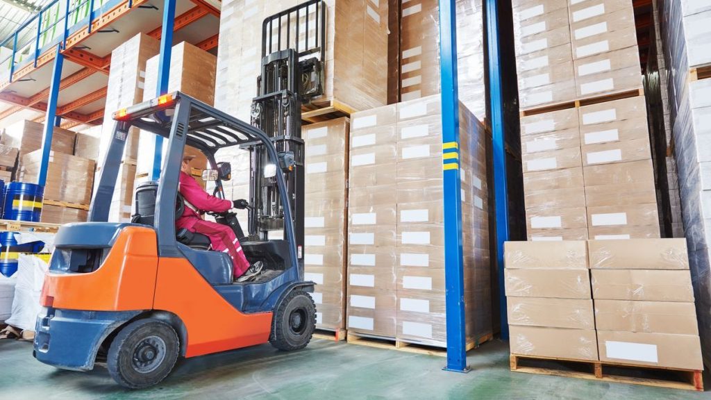
When engineers ask which wheels steer a straddle stacker, the answer focuses on the drive-end assembly. Walk‑behind and ride‑on straddle stackers typically steered through the single drive wheel located under the tiller or steering handle. The operator rotated the handle, and a mechanical or electro‑mechanical linkage pivoted this drive wheel around a vertical axis to generate yaw. Load wheels mounted in the straddle legs usually remained fixed in direction and only supported vertical and longitudinal loads.
Some compact designs used additional casters near the rear to share lateral forces and smooth transitions over floor irregularities. These casters could swivel freely but did not track a commanded steering angle like the drive wheel. Marketing descriptions sometimes stated that “all four wheels steer,” but in most industrial straddle stackers only the central drive wheel functioned as the primary steering wheel. Understanding this distinction helped designers correctly size the steering torque and select appropriate wheel materials for the drive module.
Drive Wheel, Load Wheels, And Caster Roles
The drive wheel carried traction, braking, and steering duties simultaneously. It transmitted motor torque to the floor, controlled deceleration through service and parking brakes, and rotated to change heading. Because it concentrated so many functions, engineers specified higher‑grade polyurethane or rubber compounds and robust hub bearings. The wheel often sat in a suspended or floating mount to maintain ground contact on uneven floors.
Load wheels in the straddle legs primarily supported the pallet and mast loads. They operated in pairs on each leg, distributing vertical forces and reducing floor pressure. Their rolling direction aligned with the truck’s longitudinal axis, which minimized rolling resistance but provided almost no steering authority. These wheels typically had smaller diameters than the drive wheel to keep the fork entry height low and maintain compatibility with standard pallets.
Auxiliary casters, when present, stabilized the chassis during turns and when crossing joints or ramps. They shared lateral reactions that would otherwise overload the drive or load wheels. Casters used swivel bearings and often included dampers or offset geometry to improve directional stability at low speed. Correctly balancing roles between drive wheel, load wheels, and casters allowed predictable handling, reduced tire wear, and lower operator steering effort.
Straddle Legs, Stability Triangle, And Load Moment
Straddle legs defined the outer footprint of the stacker and controlled lateral stability. Each leg extended forward and outward from the chassis, with load wheels at the front ends. Together with the drive wheel contact point, these legs formed a stability triangle. As long as the combined center of gravity of truck and load stayed inside this triangle, the stacker remained statically stable on level ground.
Load moment described how far the load’s center of gravity sat from the front face of the forks. Increasing load weight or extending the load center shifted the combined center of gravity forward and upward along the mast. When this resultant moved close to the front edge of the stability triangle, the risk of forward tip‑over rose sharply, especially during braking or ramp operation. Engineers therefore coordinated wheelbase, leg spread, and mast position with rated capacity and load center, typically 600 mm for standard pallets.
Straddle leg width also affected steering behavior. A wider leg span improved lateral stability but increased minimum aisle width and changed how the truck reacted to steering inputs in tight spaces. Designers balanced leg geometry, wheel placement, and steering range to achieve a workable compromise between maneuverability and tip‑over resistance. Operators who understood this geometry could better judge safe turning speeds and load heights in confined warehouse aisles.
Steering Mechanisms And Geometry Design
Steering design in straddle stackers determines which wheels steer a straddle stacker, how tightly it turns, and how much effort the operator needs. Engineers combine mechanical linkages, electric drive steering, and carefully tuned geometry to keep the stacker stable while still maneuverable in narrow aisles. Understanding wheel functions and steering geometry helps specify stackers correctly and diagnose handling or tire wear problems in service.
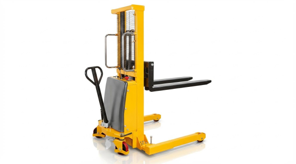
Mechanical Handle–Caster Chain Assist Systems
In basic walk-behind straddle stackers, the steering handle links mechanically to a steerable wheel set. A chain or rod assist system connects the tiller arm rotation to a caster or drive wheel yoke. When the operator swings the handle, the chain transmits torque and turns the designated steering wheel, usually the central drive wheel at the rear. This arrangement answers the question “which wheels steer a straddle stacker” for manual models: the rear drive or caster assembly steers, while the front load wheels track. Chain assist reduces steering torque, so the operator can redirect a fully loaded lift stacker in tight aisles with moderate effort. Proper chain tension and low-friction pivots are critical to avoid backlash, delayed response, and wandering during straight travel.
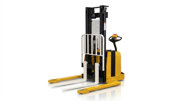
Semi- And Full-Electric Drive Wheel Steering
Semi-electric straddle stackers typically use electric lift but retain manual steering via the tiller. In these units, the rear drive wheel still provides the primary steering function, with power assistance only for traction. The handle-to-drive-wheel linkage may still use a chain or geared interface, but the electric drive reduces push–pull forces on the operator. Full-electric stackers often add more sophisticated steering integration around the powered drive wheel. A top-mounted or centrally mounted drive wheel rotates about a vertical kingpin when the operator turns the multifunction handle. The control head can incorporate sensors that modulate traction power according to steer angle, improving low-speed control and reducing tire scrub. Regardless of power level, the steering wheel on a straddle stacker is almost always the single rear drive wheel, not the front load wheels inside the straddle legs.
Key Steering Angles: Caster, Camber, Kingpin, Toe
Steering geometry defines how the steering wheel self-centers, how it loads the bearings, and how stable the stacker feels. Caster angle on the steerable drive or caster wheel tilts the steering axis relative to vertical, usually between 2° and 8°. Positive caster creates a trailing effect, so the wheel naturally aligns with travel direction and improves straight-line stability. Camber angle on industrial stacker wheels is generally near zero to keep the full tire width in contact and minimize edge wear. Kingpin inclination, often around 7° to 8°, moves the projected steering axis closer to the tire contact patch. This reduces steering scrub radius and operator effort while assisting self-centering. Toe settings, usually slight toe-in on paired wheels, control lateral stability and tire wear; however, most straddle stackers use a single steerable drive wheel, so toe primarily concerns the fixed load wheel pair in the straddle legs.
Steering Ratio, Backlash, And Operator Effort
Steering ratio describes how much handle rotation produces a given wheel steer angle. A higher ratio reduces the force the operator applies at the tiller but requires more handle travel from lock to lock. Designers balance this ratio against aisle width and the required turning radius, which often ranges around 1.4 m to 1.7 m for compact electric stackers. Backlash in chains, gears, or joints introduces dead zones where the handle moves but the drive wheel does not respond. Excess backlash degrades precision, especially when positioning pallets in racking. Minimizing backlash through tight tolerances, preloaded bushings, and proper chain adjustment keeps steering linear and predictable. Low-friction bearings, optimized steering axis placement, and appropriate steering ratio together limit operator effort, reduce fatigue, and maintain control when the stacker carries loads near its rated capacity.
Maneuvering Techniques, Safety, And Maintenance
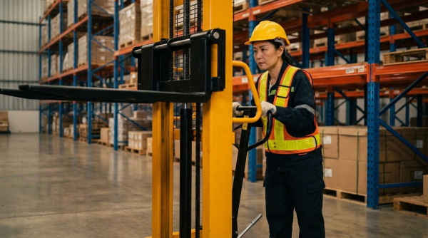
Understanding which wheels steer a straddle stacker is critical for safe maneuvering, especially in tight warehouse layouts. Steering behavior directly affects turning radius, ramp stability, and the wear pattern on drive and load wheels. Correct techniques, combined with structured maintenance, keep steering geometry within design limits and reduce accident risk.
Turning Radius, Zero-Point Turns, And Tight Aisles
In typical walk-behind straddle stackers, the steerable element is the central drive wheel located under the tiller handle. The load wheels under the forks and the wheels in the straddle legs normally track passively and do not steer, although they influence effective turning radius through their spacing and wheelbase. When operators ask which wheels steer a straddle stacker in practice, the answer is that the drive wheel sets the path while the fixed load wheels constrain how tightly the machine can rotate without scrubbing. Compact designs with a short wheelbase and narrow straddle width achieve turning radii around 1.4 m to 1.7 m, which allows operation in narrow aisles. For near zero-point turns, operators pull the tiller sideways and pivot around the drive wheel, but they must keep speed very low to avoid side loading the load wheels and overstressing the mast and chassis.
Ramp Operation, Traction, And Tip-Over Prevention
On ramps, the drive wheel again functions as the primary steering and traction wheel, while the fixed load and straddle wheels mainly carry load and stabilize the frame. Operators should travel forks upgrade when loaded and forks downgrade when descending to keep the center of gravity over the drive wheel and within the stability triangle. This practice increases traction at the driven steering wheel and reduces the risk of the truck slewing sideways. Sharp steering inputs on slopes increase lateral load transfer to the outer straddle wheels and can push the combined center of gravity outside the support polygon, causing tip-over. Operators must avoid diagonal travel on ramps, maintain low speed, and keep the mast tilted back where design permits to minimize overturning moment.
Predictive Maintenance For Wheels And Steering
Predictive maintenance focuses on the components that actually steer a straddle stacker, mainly the drive wheel assembly, steering linkage, and tiller head. Abnormal tire wear on the drive wheel or flat-spotting of load wheels often indicates misalignment, excessive turning in tight spaces, or incorrect inflation on pneumatic designs. Vibration, increased steering effort, or delayed response at the tiller suggest play in kingpins, bushings, or chain-assisted steering linkages. Maintenance teams should trend drive wheel tread thickness, bearing temperatures, and steering motor current on electric units to detect issues before failure. Lubrication of pivots and regular torque checks on fasteners in the steering path help maintain designed steering geometry and keep the machine tracking predictably.
Inspection Intervals And Service Best Practices
Daily pre-shift checks should confirm that the steerable drive wheel rotates freely, tracks straight, and responds smoothly to tiller movement. Operators should inspect all wheels for cuts, chunking, and embedded debris, because damaged load wheels increase rolling resistance and load the steering system. Weekly tasks typically include checking hydraulic oil levels and inspecting visible steering linkages and axle mounts for cracks or looseness. At intervals around six months, technicians should remove wheel assemblies as needed, inspect bearings, verify alignment of the drive wheel relative to the straddle legs, and replace worn tires or bushings. Documented inspections, combined with operator feedback on steering feel, form a closed loop that keeps maneuverability high and reduces unplanned downtime.
Summary: Steering Design, Safety, And Future Trends
Straddle stacker steering design centered on clear answers to which wheels steer a straddle stacker, how steering geometry shaped maneuverability, and how maintenance and training sustained safe operation. Typical walkie straddle stackers used the tiller handle to steer the drive wheel, while load wheels in the straddle legs primarily carried vertical load and constrained lateral motion. Some compact designs used auxiliary casters or articulated linkages so that all four corner wheels contributed to directional stability, but the primary steering authority still came from the drive wheel and its caster assembly.
Key steering geometry elements such as caster, camber, kingpin inclination, toe, and steering ratio defined how the stacker tracked, returned to center, and resisted shimmy. Designers balanced small turning radii, often near 1.4–1.7 m, against stability limits set by the stability triangle and load moment envelope. Safety practice relied on this geometry working together with correct load placement, conservative ramp techniques, and disciplined speed control in tight aisles. Predictive maintenance regimes that targeted wheels, axles, chains, and hydraulic components at defined inspection intervals reduced unexpected steering stiffness, backlash growth, and traction loss.
Future trends pointed toward wider use of semi electric order picker and full-electric steering with integrated multifunction tillers, tighter electronic control of steering ratio, and better feedback on which wheels steer a straddle stacker in real time via onboard displays or telematics. These developments aimed to cut operator effort, reduce training time, and support advanced assistance features such as speed-limited cornering and anti-tip logic. Implementers needed to consider compatibility with existing chassis layouts, IP-rated drive wheels for harsh environments, and compliance with regional industrial truck safety standards. Overall, steering technology moved toward smarter, more energy-efficient systems while preserving the fundamental mechanical robustness required for warehouse duty cycles.