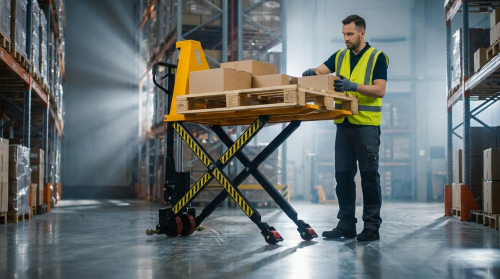
High-lift hydraulic pallet trucks combined elevated handling capability with compact manual or powered hydraulics in warehouse and manufacturing environments. This article examined how their design differed from standard low-lift pallet jacks, focusing on hydraulic circuits, structural frames, and stability limits. It then covered assembly and commissioning of HLPT-series trucks, including uncrating, mechanical build-up, chain and linkage setup, and functional testing against FEM inspection expectations. Finally, it detailed safe operation on level floors, systematic inspection routines, hydraulic service, wear-part management, and concluded with future directions for high lift pallet truck material handling technology.
Design Fundamentals of High-Lift Hydraulic Trucks
Design fundamentals for high-lift pallet trucks focused on achieving greater lift height while preserving stability and durability. Engineers balanced hydraulic performance, structural stiffness, and ergonomic operation for loads typically up to several tonnes. High-lift designs differed markedly from standard low-lift pallet trucks in geometry, hydraulic layout, and safety requirements. Understanding these fundamentals supported correct specification, safe use, and compliant maintenance.
High-Lift vs Standard Pallet Trucks: Key Differences
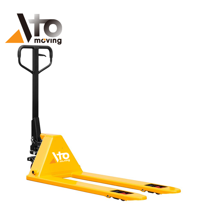
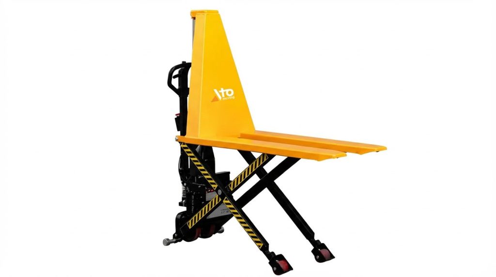
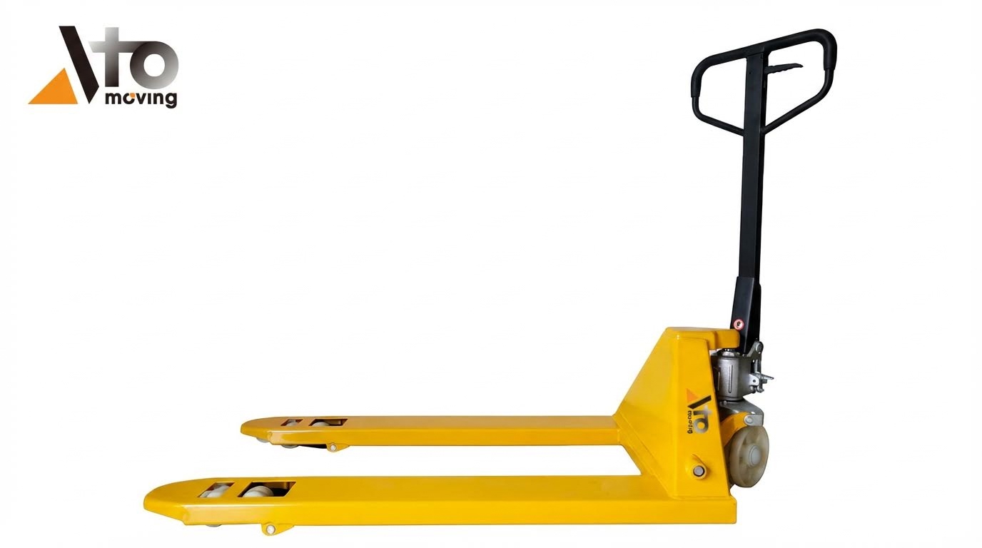
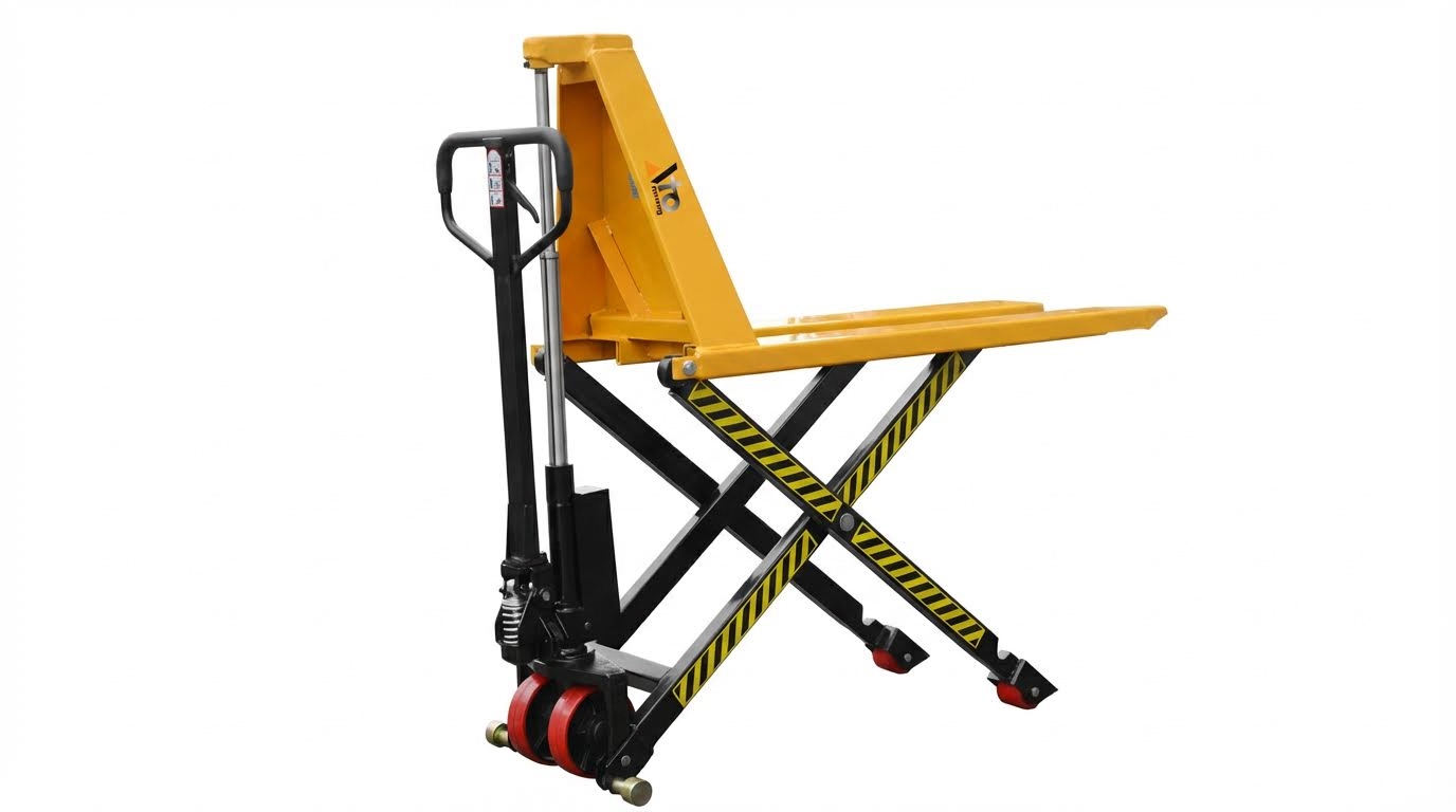
High-lift pallet trucks raised pallets to an ergonomic working height, not just a transport height. Typical high-lift units lifted up to roughly 800–1000 mm, while standard pallet jacks lifted about 75–200 mm. This extra lift required a longer-stroke hydraulic cylinder and a scissor or extended linkage structure, which increased the truck’s centre of gravity when raised. As a result, manufacturers restricted use to smooth, level, finished floors and prohibited travel with elevated loads. High-lift models often had reduced travel speed and more conservative rated capacities compared with standard trucks of similar fork size.
Core Hydraulic Circuit and Pump Assembly Basics
The hydraulic circuit in high-lift trucks used the same basic architecture as standard pallet jacks but with higher stroke and tighter sealing requirements. The pump assembly typically included a hand-actuated plunger, check valves with steel balls, springs, O-rings, and a dust seal to protect against contamination. When the operator pumped the handle, the plunger forced hydraulic oil through an inlet check valve into the main cylinder, raising the forks via the linkage. A separate release valve and rod controlled lowering by metering oil back to the reservoir. Correct sizing of springs, valve seats, and sealing elements limited internal leakage, controlled lowering speed, and protected against sudden drop in the event of minor faults. Periodic inspection for external leaks and smooth jack operation was essential to maintain safe lift performance.
Load Capacity, Lift Height, and Stability Limits
Designers defined load capacity and lift height together, because stability and structural stress increased nonlinearly with elevation. Typical manual high-lift trucks handled loads in the 1–1.5 tonne range, below the upper limits of low-lift pallet jacks, to maintain an acceptable stability margin. The load centre, usually 600 mm for standard pallets, governed tipping risk as the forks rose. At full height, even small horizontal forces or uneven floor contact could induce significant overturning moments. Therefore, standards and manuals specified strict rules: no operation on slopes, no riding on the truck, and no long-term parking with heavy loads raised. Engineers also incorporated safety factors into frame, scissor arms, and cylinder design, typically using finite element analysis and physical testing to validate deflection and buckling resistance.
Frame, Forks, and Wheels: Structural Design Points
The frame and forks of high-lift trucks required greater bending and torsional stiffness than standard models because they carried loads at larger vertical offsets. Manufacturers used welded steel frames with reinforced fork sections and accurately located bushings and pins to control play in the lifting linkage. Snap rings, nylon lock nuts, and anchor bolts held pivot points securely and limited wear-induced clearance growth. Wheels and rollers experienced higher point loads during initial lift and when the truck transitioned from static to rolling conditions. For high-lift designs, smooth, level floors were mandatory to avoid edge loading on small-diameter wheels, which could otherwise cause brinelling, flat spots, or bearing damage. Engineers selected wheel materials and diameters to balance low rolling resistance, floor protection, and durability under repeated high-load cycles.
Assembly and Commissioning of HLPT Series Trucks
Assembly and commissioning of HLPT-2045 and HLPT-2745 trucks required disciplined inspection, correct mechanical build-up, and structured functional testing. Crated units needed partial assembly using the manufacturer’s parts breakdown, while single units arrived largely pre-assembled. A systematic workflow reduced start-up faults, improved hydraulic performance, and supported compliance with FEM 4.004 and local safety regulations.
Uncrating, Inspection, and Pre-Assembly Checks
Technicians first removed packaging without cutting into painted or hydraulic surfaces. They verified the model (HLPT-2045 or HLPT-2745) and cross-checked supplied parts against the parts list, including frame, pump unit, handle, pins, bushings, and fasteners. Visual inspection focused on transport damage, bent forks, cracked welds, and deformed wheels or rollers. They also checked hydraulic components for oil traces, damaged dust seals, and loose plugs that indicated leaks. Before assembly, they confirmed the rated capacity on the nameplate and ensured it matched site requirements and intended loads.
Mechanical Assembly: Frame, Pins, Bushings, Fasteners
The base frame (HLPT-1 or HLPT-1A) formed the primary load path, so assembly tolerances were critical. Installers fitted bushings (HLPT-4) into the designated bores, then aligned pins (HLPT-3) through mating components to create low-clearance pivot joints. They secured joints with snap rings (EHPT-111) and nylon lock hex nuts TS-1541021 (M6) to prevent loosening under cyclic loading. Socket head cap screws TS-1504011 (M8 × 10) clamped auxiliary brackets and guards; installers tightened them to the specified torque using calibrated tools. After assembly, they checked fork parallelism, free movement of steering linkage, and absence of metal-to-metal binding through the full steering angle.
Pump, Chain, and Release Linkage Setup
The pump assembly included bolts HLPT-51, spring caps HLPT-52, springs HLPT-53, dust seals HLPT-54, steel balls SB-6MM, and O-rings HLPT-102. Technicians verified that check balls seated correctly and that O-rings showed no cuts or flattening. They installed the pump to the frame with the prescribed bolts, then connected the release rod and linkage, ensuring the handle positions corresponded to lift, neutral, and lower functions. The lift chain HLPT-49 (05B-1 × 15) connected the pump output linkage to the lifting mechanism; technicians set chain tension so slack remained minimal without preloading the mechanism at full lower. They lubricated the chain with light oil, as specified, and confirmed smooth, synchronized fork rise during test pumping.
Pre-Startup Functional Tests and FEM Compliance
Before commissioning, operators performed unloaded functional tests on a smooth, level, finished floor, as required for HLPT series use. They pumped the handle to full stroke to confirm uniform lift, absence of jerky motion, and no external oil leaks at seals or fittings. The release control had to lower the forks smoothly, with proportional behavior and full return to neutral without sticking. They then conducted a controlled test with a known load within the rated capacity, checking stability, steering effort, and braking by friction. For FEM 4.004 compliance, the truck entered the periodic inspection program, with documentation of initial checks, load tests, and identified corrective actions. Only after successful tests and recordkeeping did the unit enter regular warehouse service.
Safe Operation and Preventive Maintenance Practices
Safe operation and structured preventive maintenance determined the service life and reliability of HLPT high-lift pallet trucks. Operators needed clear rules for floor conditions, loading, and maneuvering to control tipping risk and protect hydraulic components. Maintenance programs focused on short, repeatable inspection routines and targeted hydraulic care to prevent leaks, internal wear, and unplanned downtime. The following subsections described proven practices aligned with typical OEM manuals and FEM 4.004 expectations.
Operating on Level Floors and Load-Handling Rules
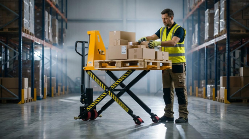
HLPT high-lift trucks were designed strictly for smooth, level, finished floors. Using them on sloping or rough surfaces increased tipping risk due to the elevated center of gravity at high lift. Operators had to approach pallets slowly and squarely, fully insert the forks, and keep the load centered between the forks. They had to respect the rated capacity at the specified load center and avoid point loads on fork tips, which overstressed forks and the pump. During travel, operators kept the load as low as practical, typically 50–80 mm above the floor, and maintained walking speed with clear visibility. Riding on the truck, carrying passengers, or pushing with excessive force violated basic safety rules and increased injury probability.
Daily and Weekly Inspection Checklists
Daily inspections focused on safety-critical items and required only a few minutes before operation. Operators checked forks for cracks, bends, or permanent deformation, and inspected the frame welds for visible damage. They verified wheels and rollers for flat spots, embedded debris, or loose fasteners, then confirmed smooth steering motion. The hydraulic system required a quick check for external oil traces around the pump, cylinder, and hoses, indicating leaks. Weekly inspections expanded this scope and aligned with typical warehouse maintenance routines. Technicians verified hydraulic oil level, checked the release valve function, and confirmed that the handle pumped smoothly without abnormal noise. They also inspected fasteners on frames, pins, and bushings for loosening, and documented findings for FEM 4.004 periodic inspection records.
Hydraulic System Care, Oil Service, and Bleeding
Hydraulic care centered on clean oil, correct fill level, and air-free operation. Low oil level reduced lifting capacity and caused erratic or slow lift, while contaminated oil accelerated seal wear and valve sticking. Service personnel inspected oil level at defined intervals and topped up with the manufacturer-specified hydraulic oil, typically around 0.3 L for a manual truck. Periodic oil changes removed dirt and water, using clean containers and tools to avoid new contamination. When air entered the system, the truck exhibited spongy lifting or poor lowering control. Bleeding procedures usually involved raising the truck without load, actuating the handle repeatedly, and cycling the release to purge air through the reservoir. If lowering remained irregular, technicians checked and adjusted the lowering valve using the specified spanner and screwdriver, following OEM torque and position guidelines.
Wear Parts, Lubrication, and Troubleshooting Basics
Wear parts on HLPT trucks included wheels, load rollers, bushings, chains, and seals. The HLPT-49 chain, for example, required periodic lubrication with light oil to maintain smooth transmission of motion between pump and lifting mechanism. Bushings and pivot pins needed thin-film lubrication at recommended intervals to limit play and reduce fretting corrosion. When wheels or rollers showed flat spots, cracks, or excessive diameter loss, technicians replaced them using appropriate tools such as retaining-ring pliers and plastic hammers. Troubleshooting began with simple checks: verify load below capacity, confirm floor level, and inspect for visible leaks or mechanical obstructions. If the truck failed to lift, technicians checked oil level, then inspected pump components such as springs, steel balls, and O-rings for damage or contamination. For persistent faults, maintenance personnel referred to the OEM troubleshooting chart and, where required, escalated complex hydraulic or structural issues to qualified workshops to maintain compliance with safety regulations.
Summary and Future Directions in High-Lift Handling
High-lift hydraulic pallet trucks extended the functional envelope of standard pallet jacks by combining vertical lift with short-distance transport. Their safe use depended on operation over smooth, level, finished floors, strict adherence to rated capacity, and disciplined load-handling practices. Correct assembly of frames, pins, bushings, fasteners, and the hydraulic pump-chain-linkage system, as documented for HLPT-2045 and HLPT-2745, ensured structural integrity and predictable hydraulic response. Regular inspections, FEM 4.004-compliant periodic checks, and systematic lubrication and oil service supported long service life and reduced unplanned downtime.
From an industry perspective, high-lift trucks bridged the gap between low-lift pallet jacks and full stackers, particularly in workstations, light assembly cells, and ergonomic picking zones. Future designs were expected to integrate more precise hydraulic metering for smoother lowering, improved dust sealing of pump assemblies, and longer-life bushings and rollers to reduce lifecycle cost. Integration with digital maintenance systems, such as QR-based service logs and sensor-assisted load monitoring, would likely support predictive maintenance and better utilization tracking. Manufacturers also tended to converge on modular pump and valve cartridges, simplifying troubleshooting and field replacement.
In practical implementation, operators and maintenance teams needed clear, model-specific procedures for pre-start checks, bleeding, oil changes, and valve adjustments, while staying within OEM limits for pressures and capacities. Facilities planners had to match fork geometry and lift height to pallet standards and workstation ergonomics, and to enforce operating restrictions on slopes and rough floors. Looking ahead, the evolution of high-lift handling equipment would probably balance robust, purely hydraulic mechanisms with selective electrification, such as powered lift with manual travel, to improve ergonomics without sacrificing simplicity. A disciplined focus on standards compliance, training, and preventive maintenance would remain the most cost-effective strategy for safe, reliable high-lift pallet truck operation.