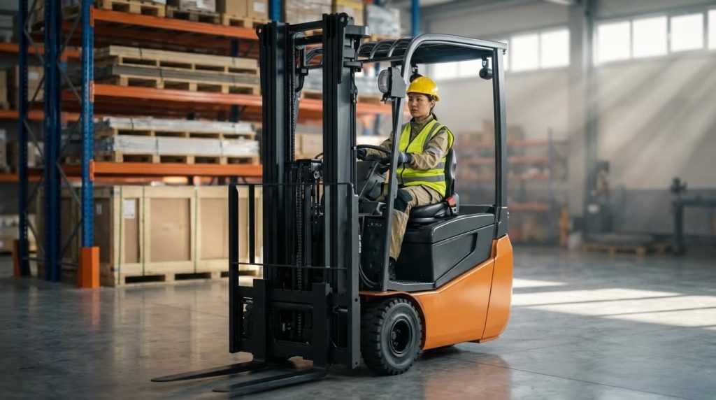
This article explains how do electric forklifts work from the inside out: battery, motors, controls, and hydraulics. You will see how energy flows from the pack to the wheels and mast, and how modern electronics keep lifting safe, efficient, and predictable in real warehouses. For more information on related equipment, check out the manual pallet jack or the hydraulic pallet truck. Additionally, explore options like the drum dolly and forklift drum grabber.
Core Architecture Of Modern Electric Forklifts
The core architecture of modern electric forklifts is a closed electrical–hydraulic system that turns battery energy into smooth drive and lift power under tight electronic control. Understanding this layout is the real answer to “how do electric forklifts work”.
At a high level, the battery feeds DC power into electronic controllers, which convert and meter it to drive motors and hydraulic pump motors. Sensors and software constantly adjust torque, speed, and lift to keep the truck stable, efficient, and within safe limits.
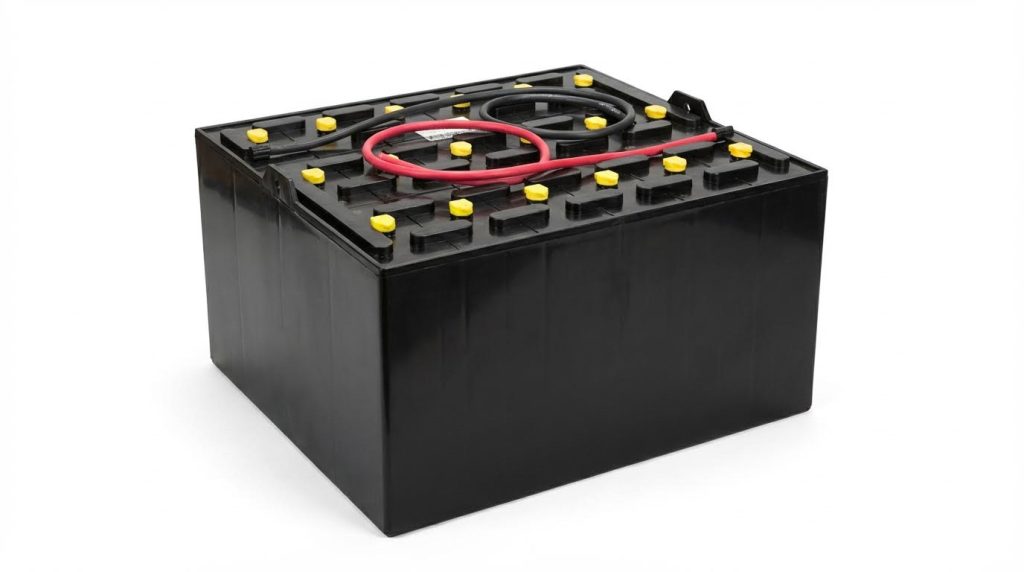
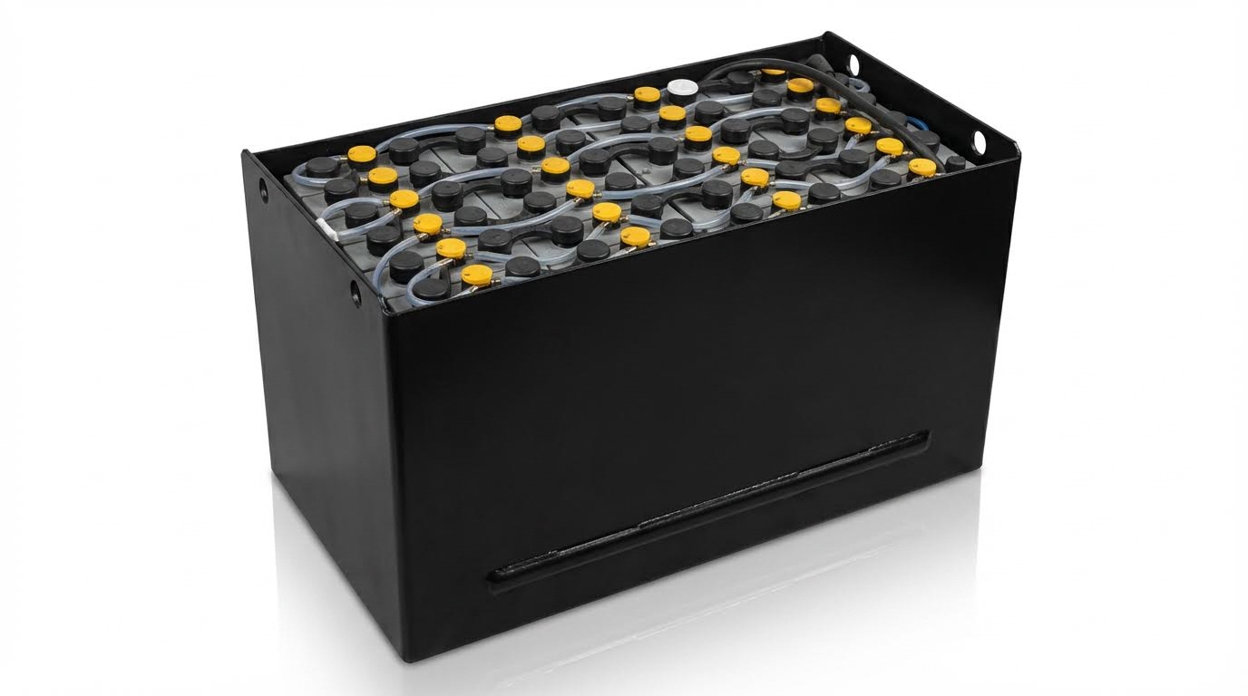
- Battery pack: High‑capacity lead‑acid or lithium‑ion – The single energy source for drive, steering, hydraulics, and electronics.
- Drive system: Electric traction motors on the drive axle – Converts electrical power into tractive effort at the wheels.
- Hydraulic system: Lift motor + pump + cylinders – Turns electrical power into mast and attachment movement.
- Electronic controller: Inverter and logic board – Decides how much current goes where, and when.
- Sensors and switches: Pedals, joysticks, encoders, pressure and tilt sensors – Feed real‑time data so the controller can regulate power safely.
| Subsystem | Main Components | Energy Form In / Out | Operational Impact |
|---|---|---|---|
| Energy storage | Lead‑acid or Li‑ion battery, BMS | DC electrical → DC electrical | Defines operating hours per charge and peak current for lift/drive. |
| Traction drive | AC or DC drive motors, gearbox, drive axle | DC electrical → mechanical rotation | Determines acceleration, gradeability, and top speed. |
| Hydraulic lift | Lift motor, hydraulic pump, valves, cylinders | DC electrical → hydraulic pressure → linear force | Sets lift capacity (kg) and mast speed (m/s). |
| Control electronics | Inverters, logic controller, contactors | Low‑power DC control → high‑power switching | Coordinates safe, smooth response to operator inputs. |
| Feedback & safety | Sensors, limit switches, overload and tilt protection | Mechanical / hydraulic states → signals | Prevents overload, instability, and component damage. |
💡 Field Engineer’s Note: When troubleshooting “weak power,” always map the whole chain: battery voltage under load, controller output, then motor current. Many “bad motor” complaints turn out to be voltage sag or current limiting upstream.
Power flow from battery to wheels and mast
The power flow in an electric forklift runs from battery, through electronic controllers, into traction and lift motors, and finally into wheels and mast hydraulics. This is the backbone answer to how do electric forklifts work in daily operation.
- Battery output: The battery supplies DC voltage and current sized for both drive and lift demand – Defines how much simultaneous driving and lifting you can support.
- Main contactor & fuses: High‑current switching and protection – Isolate the pack and protect against short circuits.
- Traction controller: Converts DC to 3‑phase AC and meters current – Controls wheel torque and speed based on accelerator input.
- Lift controller: Feeds a separate motor for the hydraulic pump – Controls lift and tilt speeds based on joystick or lever position.
The same battery usually feeds both the traction and hydraulic circuits. During heavy lifting, the controller can temporarily limit drive current so the lift motor gets enough power to build hydraulic pressure for the cylinders as described in modern control schemes. When the operator releases the lift controls and focuses on travel, the hydraulic demand drops and more current becomes available for traction.
| Stage | Component | Energy Conversion | Operational Impact |
|---|---|---|---|
| 1 | Battery + BMS | Chemical → DC electrical | Voltage stability under load keeps performance consistent late in the shift. |
| 2 | Main contactor & protection | DC routing and isolation | Allows safe power-up / shutdown and fault isolation. |
| 3 | Traction inverter/controller | DC → variable‑frequency AC | Fine control of wheel torque for smooth starts and ramps. |
| 4 | Drive motor(s) | AC electrical → shaft torque | Propels the truck, handles gradients and acceleration. |
| 5 | Lift controller + pump motor | DC/AC → pump rotation | Generates hydraulic pressure for mast lift/tilt. |
| 6 | Hydraulic pump, valves, cylinders | Hydraulic pressure → linear force | Raises/lowers forks and tilts mast with controlled speed. |
Regenerative features improve the overall efficiency of this power path. During braking or when lowering a load, the traction or lift motor can operate in reverse as a generator, feeding energy back into the battery instead of wasting it as heat in regenerative systems. This extends run time per charge and reduces heat stress on hydraulic oil and electrical components.
How the power split feels to the operator
When the operator floors the accelerator with a heavy pallet raised, the truck will usually limit travel speed. The controller prioritizes mast stability and lifting torque over traction power, which is why the truck “feels” slower during high lifts.
💡 Field Engineer’s Note: On trucks that “nose-dive” in performance halfway through the shift, check for aggressive current limiting settings in the controller. With modern batteries and efficient motors, you can often relax limits slightly without sacrificing safety or battery life.
Key components and control signal paths
The key components and control signal paths in an electric forklift link operator inputs and sensor feedback to high‑power switching in the controllers and motors. This electronic nervous system is central to how do electric forklifts work safely in tight aisles.
- Operator input devices: Accelerator pedal, direction switch, steering, lift/tilt levers or joystick – Generate low‑voltage signals that represent the driver’s intent.
- Central controller: Microprocessor with software logic – Interprets inputs, applies safety rules, and commands power electronics.
- Power electronics: IGBTs/MOSFETs in traction and lift inverters – Translate controller commands into controlled high‑current outputs.
- Sensors: Motor speed encoders, hydraulic pressure sensors, load and height sensors, temperature probes – Provide real‑time feedback for closed‑loop control.
Modern electric forklifts use electronic control systems to manage the interaction between the motor, hydraulic pump, and lifting cylinders. Sensors measure motor speed, fluid pressure, load weight, and lift height, while the controller adjusts motor output in real time to match the demand. If the forks approach maximum height, the controller automatically reduces lift speed to avoid mechanical shock and mast stress.
| Signal Path | From → To | Signal Type | Operational Impact |
|---|---|---|---|
| Travel command | Accelerator pedal → traction controller | Low‑voltage analog or CAN | Sets wheel torque and speed for smooth driving. |
| Direction command | Fwd/Rev switch → traction controller | Digital | Determines current flow direction in drive motor windings. |
| Lift command | Joystick or lever → lift controller | Proportional signal | Controls pump speed and thus lift / lower speed. |
| Load feedback | Pressure / load sensor → main controller | Analog / digital | Triggers overload protection and speed reduction. |
| Height feedback | Height sensor / limit switch → controller | Digital / incremental | Enforces soft stops and reduced speed near full height. |
| Thermal feedback | Motor and battery temperature → controller/BMS | Analog | Initiates derating to prevent overheating. |
- Safety thresholds: The controller stops or derates lifting if it detects overcurrent, overheating, or excessive load through built‑in protections – Prevents damage and tip‑over.
- Valve actuation: Directional and flow control valves respond to electrical signals – Route hydraulic fluid to raise, hold, or lower with controlled speed.
- Monitoring & diagnostics: Dash displays and diagnostic ports show voltage, temperature, and fault codes manual pallet jack to support predictive maintenance – Reduces unplanned downtime.
How control logic shapes “feel” and safety
By tuning acceleration ramps, lift‑speed curves, and regenerative braking strength in software, engineers can make the same hardware feel aggressive for outdoor yards or very gentle for narrow indoor aisles. The underlying signal paths stay the same; only the logic changes.
💡 Field Engineer’s Note: When a truck “does nothing” after a control board change, trace the low‑voltage side first: dead pedals, broken joystick pots, or CAN wiring faults will completely block power, even if the battery and motors test perfectly on their own.
Motors, Controllers, And Hydraulics In Detail

This section explains how electric forklift motors, controllers, and hydraulics turn battery energy into smooth driving and lifting, so anyone asking “how do electric forklifts work” can picture the hardware doing the job.
Drive motor types and selection criteria
Drive motors convert battery power into tractive force at the wheels, and choosing the right type directly impacts acceleration, gradeability, and maintenance cost over the truck’s life.
| Motor Type | Key Characteristics | Typical Use In Electric Forklifts | Operational Impact |
|---|---|---|---|
| AC induction motor | Brushless, uses electromagnetic induction, high efficiency, low maintenance | Main drive motor on most modern trucks | Long life, good energy efficiency for 8–10 hour shifts under consistent conditions |
| Brushless DC / Permanent magnet DC | No brushes, uses permanent magnets, compact, very efficient | Smaller drive units, steering or auxiliary drives | Lower maintenance, good low‑speed control, but higher upfront cost due to magnets |
| DC series motor | High torque at low speed, uses brushes, lower efficiency | Older or cost‑sensitive models for heavy starts | Strong start on ramps, but needs brush changes and more servicing over time |
| DC shunt / separately excited DC | Good speed stability and fine control, more complex | Precision handling where constant travel speed matters | Smooth, predictable travel but higher system complexity and cost than simple DC |
| Synchronous AC / IPM | High efficiency, high torque density, needs advanced controller | Premium models targeting maximum energy savings | Longer runtime per charge and strong performance on gradients with low losses |
In practical fleet terms, AC induction and other brushless designs now dominate because they cut out brush and commutator wear, which reduces service stops and keeps efficiency high over thousands of hours. Traditional DC series motors still appear where purchase price is the main driver and high starting torque is needed, but operators pay later in brushes, commutator turning, and downtime.
- Duty cycle and load profile: Match continuous rating to typical 8–10 hour shifts – avoids overheating when trucks run near maximum capacity most of the day.
- Battery voltage and chemistry: Ensure motor and controller are designed for the truck’s lead‑acid or lithium‑ion system – prevents undervoltage faults and wasted capacity.
- Environment: Choose sealed or better‑cooled motors for outdoor yards or dusty sites – reduces ingress‑related failures.
- Control precision: Use motors that respond well to modern speed control (e.g. PWM, vector control) – gives smooth low‑speed maneuvering in tight aisles.
- Lifecycle cost: Compare brushless vs brushed on 5–7 year horizons – higher CapEx can be offset by lower maintenance and energy use.
💡 Field Engineer’s Note: When specifying drive motors for sites with long ramps or dock approaches, always check continuous torque at low speed, not just peak ratings; trucks that “feel fine” on flat concrete can stall or overheat on a 30–40 m ramp under full load.
Lift motors, pumps, and hydraulic circuits
Lift motors and hydraulic circuits turn electrical energy into high-pressure oil flow that raises and lowers the mast smoothly while sharing power with the drive system.
Most modern electric forklifts use a dedicated AC motor to drive a hydraulic pump for lifting and auxiliary functions, because this combination offers high efficiency and low maintenance compared with older DC lift motors. When the operator moves the lift lever or joystick, the controller commands the lift motor to spin the pump, creating hydraulic pressure that feeds one or more lift cylinders in the mast for vertical motion.
| Hydraulic Component | Main Function | What It Controls | Operational Impact |
|---|---|---|---|
| Lift motor | Drives hydraulic pump using battery power | Available hydraulic flow and pressure | Sets maximum lift speed and ability to handle rated load at full height under varying loads |
| Hydraulic pump | Converts motor torque into oil flow | Flow rate (m³/h) and system pressure (bar) | Determines how fast the mast can raise a 1,000–2,500 kg pallet |
| Lift cylinders | Turn oil pressure into linear force | Mast movement up/down | Provide the actual lifting force; bore size and pressure define capacity for given load |
| Directional control valves | Route oil to raise, hold, or lower | Fork direction of travel (up/down/tilt) | Enable precise operator control and stable load holding at height |
| Flow control valves | Limit and meter oil flow | Lift and lower speed | Prevent jerky motion and allow gentle placement of loads on racking |
| Pressure relief valves | Dump excess pressure safely | Maximum system pressure | Protect structure and hoses from overload or blocked flow situations by limiting pressure |
Because both traction and lifting take power from the same battery, the controller must arbitrate between them. Under heavy lifting, it can temporarily reduce drive power so enough current is available for the lift motor, then restore full traction once the mast is stationary, which is a key part of how electric forklifts work efficiently throughout a shift without overloading the circuit.
- Hydraulic vs mechanical lifting: Hydraulics offer higher power density and smoother motion – better for 3–6 m mast heights and heavy pallets.
- Valve tuning: Proper flow control and cushioning at end‑of‑stroke – reduces mast shock and extends bearing life.
- Regenerative lowering: Using cylinders and motor in reverse – recovers some energy back to the battery when lowering loads.
- Safety locks and non‑return valves: Hold load if a hose fails or pump stops – prevents sudden fork drop during power loss.
💡 Field Engineer’s Note: In cold stores below 0°C, hydraulic oil viscosity increases sharply; if you do not specify low‑temperature oil and slightly larger return lines, operators will complain about slow, jerky lift long before the truck hits its nominal service interval.
Electronic controllers, sensors, and safety logic

Electronic controllers, sensors, and safety logic coordinate battery, motors, and hydraulics in real time, deciding how much current goes where so the truck behaves predictably and safely.
The central electronic controller receives inputs from the accelerator, lift and tilt levers, and various sensors, then modulates current to the drive and lift motors. It uses techniques such as pulse width modulation to adjust motor torque and speed efficiently across different loads and operating conditions, keeping performance smooth while limiting energy waste during variable‑speed work.
- Motor speed sensors: Feed back actual rpm – allow closed‑loop control for smooth acceleration and travel speed limiting.
- Pressure and load sensors: Monitor hydraulic pressure and load weight – let the controller boost current for heavy lifts or stop before overload.
- Lift height and position sensors: Detect mast and fork position – enable automatic slow‑down near maximum height to cut mast stress.
- Temperature and voltage sensors: Watch motor and battery health – trigger derating or alarms before components overheat or sag.
On the hydraulic side, the controller manages proportional valves and pump speed so that small joystick movements translate into small, predictable mast movements. Safety logic also supervises these systems: it can halt lifting if it detects overcurrent, over‑temperature, or abnormal pressure spikes, and it works with non‑return valves and mechanical locks to keep forks stable if power is lost during operation.
- Ergonomic operator controls: Joysticks or levers send proportional signals – reduce fatigue and improve fine placement on high racking.
- Monitoring and diagnostics: Dash displays and data logs – help technicians troubleshoot faults quickly and support predictive maintenance.
- Energy management: Prioritizes lift vs drive and may enable regenerative braking – extends runtime per charge and protects the battery.
💡 Field Engineer’s Note: When fleets complain that “the truck feels weak,” checking controller settings often fixes the issue; conservative torque limits, speed caps, or aggressive thermal derating can make a healthy truck behave like it is undersized for the job.
Battery Systems, Charging, And Fleet Optimization
Battery choice, charging strategy, and fleet optimization determine how do electric forklifts work over a full shift: runtime, safety, and cost per pallet all start with the energy system design.
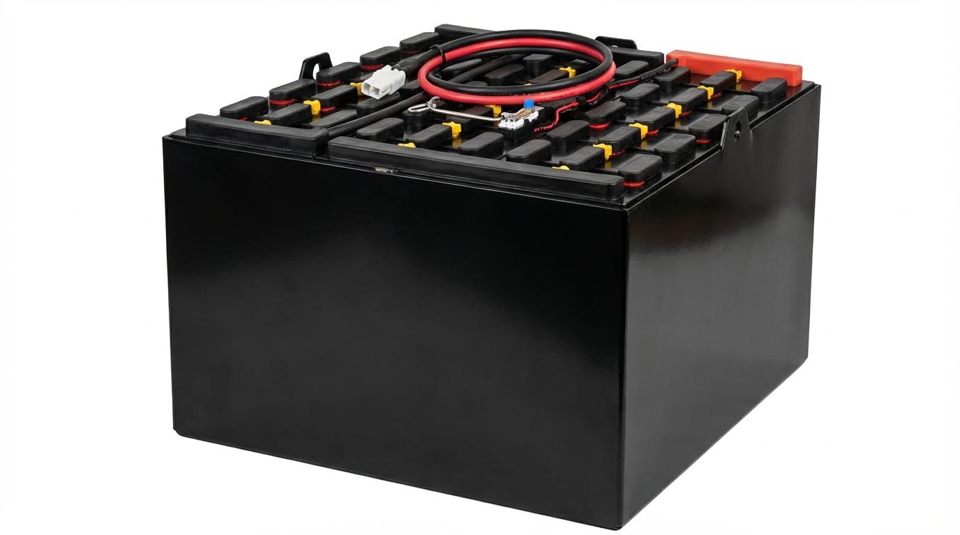
In modern electric forklifts, the battery is not just a “fuel tank”; it is the main structural energy module feeding drive motors, hydraulic pumps, and electronics. Understanding chemistry, charging, and management is what separates a 3-year battery problem from a 10-year fleet asset.
Lead-acid vs. lithium-ion performance and TCO
Lead-acid and lithium-ion batteries make electric forklifts work very differently in runtime, maintenance, and lifetime cost, even when the truck frame looks identical.
Both chemistries deliver DC power to the traction and lift systems, but they behave very differently in terms of usable energy window, charging flexibility, and temperature sensitivity. That directly affects how many trucks you need in a fleet and how often they stop to charge.
| Parameter | Lead-acid traction battery | Lithium-ion traction battery | Operational Impact / Best For… |
|---|---|---|---|
| Typical usable DoD in daily use | ≈70–80% recommended to avoid damage | Can tolerate partial charges; 50–80% DoD common | Li-ion supports frequent opportunity charging, ideal for multi-shift work |
| Charging pattern | Prefers full charge cycles and recharge around 20–30% remaining to avoid sulphation Lead-acid charging practices | Can be topped up after each shift or break without memory effect Li-ion charging practices | Lead-acid suits single-shift, Li-ion suits irregular, high-utilization schedules |
| Maintenance | Regular watering, cleaning, and vent inspection needed Watering and cleaning | Essentially maintenance-light; no watering, sealed pack | Lead-acid adds weekly tasks; Li-ion reduces labor and downtime |
| Temperature sensitivity | High heat (≈35°C) can cause up to 40% capacity loss per year Lead-acid temperature impact | High heat (≈35°C) can cause about 20% capacity loss over two years Li-ion temperature impact | Li-ion holds up better in hot warehouses; both need thermal control |
| Optimal operating temp range | ≈20–30°C recommended for best life Lead-acid temp range | ≈15–25°C recommended for best life Li-ion temp range | Cold storage and hot loading docks require HVAC or battery heaters/coolers |
| Depth of discharge vs cycle life | Deep discharges sharply reduce life; best kept shallow | At 50% DoD, LiFePO4 can reach ≈6,000 cycles vs ≈3,500 cycles at 80% DoD Li-ion DoD impact | Fleet policies on when operators plug in have huge TCO impact |
| Storage behavior | Self-discharge ≈5–10% per month; must be stored fully charged with periodic top-ups Lead-acid storage | Best stored around 50% State of Charge and ≈15°C to slow aging by ≈75% vs full-charge storage Li-ion storage | Critical for seasonal fleets and spare packs |
| Safety and gas management | Generates hydrogen gas during charge; needs ventilation and no open flames Ventilation requirements | Minimal gas release; relies on electronic protection | Lead-acid requires dedicated charge rooms; Li-ion simplifies layout but needs BMS oversight |
From a total cost of ownership (TCO) perspective, lithium-ion usually carries a higher purchase price but pays back through longer cycle life, reduced maintenance, and the ability to share fewer trucks across more shifts. Lead-acid still makes sense where capital is tight and duty cycles are light and predictable.
- Single-shift, low-hour sites: Lead-acid – Lower upfront cost, simple nightly full charge routine.
- Multi-shift, 16–24 h operations: Lithium-ion – Fast opportunity charging and higher cycle life reduce fleet size.
- Hot or harsh environments: Lithium-ion – Better thermal robustness when kept in its ideal range.
💡 Field Engineer’s Note: When we model how do electric forklifts work over 5–7 years, the biggest hidden cost is not the battery itself but the extra trucks, chargers, and labor you need to cover downtime from slow lead-acid charging and maintenance.
Charging methods, BMS, and thermal management
Charging strategy, Battery Management Systems (BMS), and temperature control decide whether your forklift battery reaches its rated cycle life or fails years early.
In practical terms, this is where the theory of how do electric forklifts work meets day-to-day habits: when operators plug in, how chargers are set, and how heat is managed around the pack.
Charging practices and safety
Correct charging protects battery chemistry, reduces fire and explosion risks, and stabilizes voltage delivery to motors and hydraulics.
- Lead-acid recharge window: Charge when around 20–30% capacity remains to prevent sulphation and lifespan loss Lead-acid recharge range – Maintains plate integrity.
- Lead-acid full cycles: Prefer complete charge cycles rather than frequent short top-ups Full charge guidance – Equalizes cells and keeps capacity balanced.
- Li-ion routine charging: Regular charging after each shift or break is acceptable and recommended Li-ion charging habits – Supports high uptime without memory effect.
- Overcharge protection: Smart chargers and BMS regulate voltage and current to avoid overheating and cell damage Overcharging prevention – Prevents plate corrosion and gas build-up.
- Ventilation for lead-acid: Charging areas must be well ventilated to disperse hydrogen gas and heat Ventilation guidance – Reduces explosion and fire risk.
Lead-acid watering and cleaning basics
Lead-acid batteries need regular watering and cleaning to keep internal chemistry stable and external connections safe. Water levels should be checked weekly or every 5–10 charge cycles, using distilled or deionized water and topping up after the battery has cooled, keeping liquid just above the plates but below the caps Watering intervals. Terminals, connectors, and cases should be cleaned on a weekly to quarterly schedule, using neutralizing agents and correct wastewater disposal to control corrosion and stray currents Cleaning procedures.
Battery Management Systems (BMS) and monitoring
A modern BMS is the “brain” that makes electric forklifts work safely by supervising every cell and controlling how energy flows in and out.
Instead of relying on operator judgment alone, the BMS enforces limits, balances cells, and feeds data to fleet managers.
- Cell protection: BMS monitors cell voltages, temperatures, and currents to prevent overcharge and overload conditions BMS protection – Prevents thermal runaway and premature aging.
- Cell balancing: Advanced systems keep cell voltages within about ±0.02 V, adding up to 1,000 extra cycles compared to unmanaged packs Cell balancing benefits – Ensures all cells age evenly.
- Data logging and prediction: BMS with connectivity can log performance and predict failures over 100 cycles in advance Predictive BMS – Enables scheduled replacement instead of surprise breakdowns.
- Dashboard integration: Voltage, temperature, and alarms can be displayed on truck screens, helping operators spot issues early – Improves frontline decision-making.
On top of BMS functions, facility-level monitoring systems track battery temperatures, voltages, and charge events across the fleet. This helps optimize charger placement, shift patterns, and spare battery inventory.
💡 Field Engineer’s Note: When you see frequent current limiting and high-temperature alarms in the BMS logs, it is often not a “bad battery” but an undersized pack or charger for the duty cycle. Fix the sizing, not just the hardware.
Thermal management and depth of discharge policies
Thermal control and depth-of-discharge (DoD) limits are the two levers that most strongly influence battery life and therefore fleet economics.
Because motors, controllers, and hydraulics all draw from the same pack, any heat or deep cycling penalty hits every function of how electric forklifts work.
- Temperature window: Keeping lithium-ion around 15–25°C and lead-acid around 20–30°C optimizes internal reactions and extends life Optimal temperature ranges – Reduces chemical side reactions.
- High-temperature damage: At ≈35°C, lithium-ion can lose about 20% capacity over two years, while lead-acid can lose ≈40% capacity annually High temperature impact – Explains why hot
Final Thoughts On Specifying Electric Forklifts
Electric forklifts only deliver safe, low‑cost work when you treat the truck as one integrated energy and control system. Motors, hydraulics, controllers, and batteries share the same pack, so weak design or setup in one area will show up as lost runtime, slow lifts, or unstable handling in another.
Engineering teams should start with the duty cycle. Size drive and lift motors for continuous torque, not brochure peaks, and match hydraulic pump and valve tuning to real load weights and mast heights. Verify that control logic prioritizes stability: automatic speed reduction at height, overload cut‑outs, and smooth acceleration ramps protect both structure and operators.
Battery choice and charging policy then lock in lifetime cost. Use lead‑acid for predictable single shifts with clear charge windows. Use lithium‑ion with a strong BMS where you need opportunity charging, high utilization, or hot environments. In both cases, keep temperature in the recommended band and enforce depth‑of‑discharge limits through settings, not just training.
For operations and fleet managers, the best practice is simple: specify components as a matched set, log how trucks are actually used, and adjust controller and charging parameters over time. That approach turns an electric forklift from a black box into a controllable, predictable asset for your Atomoving fleet.
Frequently Asked Questions
How Do Electric Forklifts Work?
Electric forklifts operate using an electric motor powered by a rechargeable battery. The motor drives the hydraulic system, which controls the lifting and lowering of the forks. Here’s a simplified breakdown:
- The electric motor powers a hydraulic pump.
- The hydraulic pump generates pressure to move hydraulic fluid.
- This fluid pressure pushes a piston in the lift cylinder, raising or lowering the forks.
- The operator controls these functions using levers or buttons on the forklift’s dashboard.
Unlike internal combustion forklifts, electric forklifts produce zero emissions, making them ideal for indoor use. For more details on electric-powered equipment, check out this guide: Power Pallet Truck Guide.
Do Electric Forklifts Use Hydraulics?
Yes, most electric forklifts rely on hydraulics to lift and lower loads. The electric motor powers a hydraulic pump, which pressurizes fluid to move pistons in the lift cylinders. This mechanism allows precise control over the height and position of the forks. While some smaller models may use mechanical systems, hydraulics remain the industry standard due to their efficiency and reliability.