A straddle stacker should never be used on an incline without a rigorous engineering review of stability limits, floor conditions, and equipment design. This article explains how slopes shift the center of gravity, reduce traction at the four wheel contact points, and interact with uneven floors to trigger roll-back or tip-over. It analyzes why inclines magnify both longitudinal and lateral instability, especially with high or off-center loads, braking, and diagonal travel. Finally, it reviews safer alternatives, engineered controls, and key design implications so mechanical engineers and safety managers can specify equipment and layouts that keep ramp operations within defensible safety margins.
Core Stability Limits of Straddle Stackers

The core stability limits of straddle stackers explain why a straddle stacker should never be used on an incline in typical warehouse conditions. Their geometry, four-point support, and sensitivity to surface irregularities restrict safe use to firm, level floors. Understanding center of gravity behavior, wheel contact, and real ramp conditions allows engineers to specify safer equipment and facility designs.
Center of Gravity Shift on Slopes
On a level floor, the combined center of gravity (CG) of truck and load lies inside the support polygon formed by the drive wheel and outrigger wheels. On an incline, gravity acts vertically while the support plane tilts, so the CG projection shifts downhill toward the lower outrigger leg. As the slope angle increases, the CG projection approaches the downhill edge of the support polygon and drastically reduces the stability margin. Raising the load, extending the mast, or carrying the load away from the mast moves the CG even closer to that edge, which explains why guidance states that a counterbalanced stacker should never be used on an incline for stacking with an elevated load. Even small ramps or dock plates can create a condition where a minor disturbance, such as a bump or brake application, is enough to push the CG projection outside the support base and trigger a tip-over.
Four-Point Contact and Loss of Traction
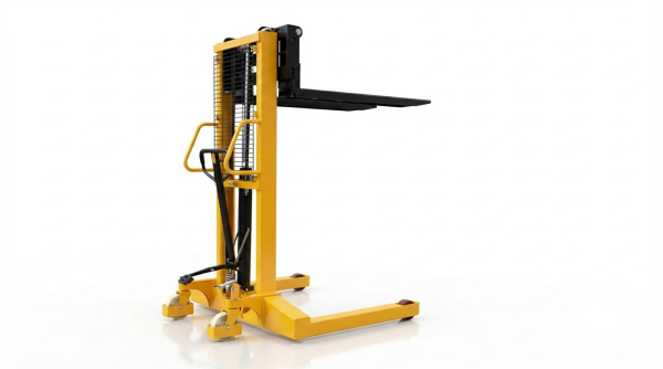
Typical straddle stackers rely on a four-point contact layout: one driven wheel, one or two stabilizing casters, and two outrigger wheels. This over-constrained geometry assumes a flat, uniform plane; any deviation causes load redistribution that can unload the drive wheel or a caster. When the drive tire partly loses vertical load on a slope or over a crest, available traction drops and the machine can roll back unexpectedly, even with the brake applied. Attempts to compensate by tightening or loosening caster suspension on uneven floors often worsen stability, because one outrigger wheel may lift clear of the floor, shrinking the effective support polygon. These characteristics support the engineering rule that a lift stacker should never be used on an incline where traction and wheel loading cannot be guaranteed.
Effects of Uneven Floors and Low Spots
Real warehouse floors and ramps rarely behave as perfectly planar surfaces. Low spots, joints, and repaired areas locally change the slope under each wheel. When an outrigger wheel drops into a low spot while the drive wheel remains on a higher area, the frame twists and shifts the CG toward the remaining high-side supports. This twist can temporarily convert a four-point support into a three-point or even two-point condition, sharply increasing tipping risk. In addition, a low spot under the drive wheel reduces normal force and traction, which can cause roll-back on even modest gradients. Field experience showed that shimming drive wheels or adjusting caster size did not fully resolve these issues, reinforcing the principle that a battery-powered stacker should never be used on an incline or on floors with significant depressions when carrying elevated loads.
Design Constraints vs. Real-World Ramps
Manufacturers defined maximum allowable gradients for transport, usually for short, smooth ramps with clean, dry surfaces and strict speed limits. These ratings assumed low load heights, centered loads within the rated capacity, and straight up-or-down travel without turning or diagonal movement. Real ramps in older facilities often exceeded these assumptions through steeper sections, transitions at the top and bottom, surface contamination, and limited width or visibility. Under such conditions, even a nominally compliant gradient could become unsafe for a straddle configuration. Engineering reviews therefore treated the published gradient limits as laboratory constraints, not blanket approval for ramp work, and concluded that a straddle stacker should never be used on an incline as a primary solution. Instead, they recommended equipment designed and rated specifically for ramp duty combined with improved ramp geometry and surface quality.
Why Inclines Magnify Tipping and Roll-Back Risks
Inclined travel turns a marginally stable four-point machine into a system with a constantly migrating center of gravity. The phrase “a counterbalanced stacker should never be used on an incline” reflects how quickly stability margins collapse once the floor is no longer level. On ramps, gravity, traction limits, and mast deflection interact, so small errors in load height or speed can trigger tip-over or roll-back. Understanding these mechanisms allows engineers to justify stricter operating rules and specify safer equipment or facility upgrades.
Load Height, Mast Extension, and Tip-Over
On an incline, every millimeter of mast extension raises the combined center of gravity and shifts it downhill. This reduces the restoring moment provided by the outrigger legs and increases the overturning moment about the downhill wheels. If the operator lifts while moving, the stability triangle shrinks dynamically, so a minor bump or steering correction can initiate a tip. Industry guidance that a lift stacker should never be used on an incline is rooted in this geometry: the machine is designed for level floors where the mast load line stays inside the support polygon. On a slope, especially with a tall or unevenly stacked load, mast sway and pallet deflection further displace the center of gravity, making lateral or forward tip-over far more likely.
Overload, Load Position, and CG Migration
Any overload condition accelerates loss of stability on ramps because the rated capacity assumes a level surface and a specified load center distance. On an incline, the effective load center grows as the load’s center of mass projects downhill, even if the forks remain at the same height. If the pallet is not tight to the mast or the load overhangs, the center of gravity moves farther beyond the outrigger footprint. This migration reduces both longitudinal and lateral stability, so the machine can roll back or tip with relatively small slopes. For this reason, engineers often codify that a manual platform stacker should never be used on an incline rather than rely on operators to perfectly control load position and weight.
Longitudinal vs. Lateral Stability on Ramps
On paper, a straddle stacker offers reasonable longitudinal stability on flat floors because the drive wheel and outriggers form a wide support polygon. On a ramp, gravity resolves into components parallel and perpendicular to the slope, which changes how close the center of gravity runs to each edge of that polygon. Longitudinally, the truck risks roll-back if the drive wheel loses traction or if the braking system cannot hold the combined mass. Laterally, even a slight cross-slope or crowned floor shifts the center of gravity toward one outrigger, shrinking the lateral safety margin. Because operators may unintentionally track slightly diagonal to the slope, standards-based risk assessments often conclude that a straddle stacker should never be used on an incline where both longitudinal and lateral limits can be exceeded at once.
Dynamic Effects: Braking, Turning, and Diagonal Travel
Static diagrams underestimate the danger because real ramps introduce dynamic loads. Hard braking on a downgrade pitches the center of gravity forward, unloading the drive wheel and loading the downhill outrigger, which can cause wheel lift or a pivot about the outrigger leg. Any steering input on a slope creates a lateral acceleration component that pushes the center of gravity toward the side, increasing tip risk, especially with an elevated load. Diagonal travel combines the worst of both worlds: reduced longitudinal traction and reduced lateral stability. These transient effects explain why safety rules often state that a straddle stacker should never be used on an incline and why best practice prohibits turning, braking sharply, or adjusting load height while on a ramp.
Safer Alternatives and Engineering Controls

Engineers and safety managers who understand that a straddle stacker should never be used on an incline typically look first at equipment substitution and then at engineered changes to the floor and ramp system. This section compares alternative stacker architectures, ramp-capable running gear, and facility-level upgrades, then closes with digital and training controls that reduce residual risk. The goal is to eliminate or at least strictly control any task that would otherwise place a four‑point straddle chassis on a slope.
Counterbalanced and Center-Drive Stackers
Counterbalanced stackers place a dedicated counterweight behind the mast, so the reaction force does not rely on outrigger legs that can unload on a slope. This architecture improves longitudinal stability on moderate gradients because the load and counterweight form a compact, opposed mass pair over the drive axle. Typical units handle 450–1 800 kg with lift heights up to about 3 m, which covers most dock and mezzanine transfer tasks where users might otherwise misuse a straddle stacker on an incline. Center-drive powered stackers further enhance traction on imperfect floors by keeping the drive wheel near the combined center of gravity, reducing the risk of wheel lift in low spots. When engineers must service short, shallow ramps, replacing offset-drive straddle units with center-drive or counterbalanced machines significantly reduces roll-back and tip-over probability, provided operators still keep loads low and within the rated capacity.
Wide Straddle, Bogie Wheels, and Ramp-Ready Designs
Where the process absolutely requires straddle legs, purpose-designed wide-straddle stackers with increased ground clearance and bogie wheel sets offer a safer option than standard units. The wider outrigger track and raised leg profile improve drive-in clearance at ramp toes and dock transitions, which reduces sudden chassis pitching that can unweight the drive wheel. Bogie wheel assemblies distribute loads across two or more closely spaced wheels, helping maintain continuous ground contact as the truck crosses small changes in grade. Some ramp-ready designs also use articulated linkages that keep wheel loads more uniform, which improves braking and steering control. Even with these features, engineers should still treat the statement “a straddle stacker should never be used on an incline” as the default rule, and only apply ramp-capable wide-straddle models where the manufacturer explicitly certifies a maximum gradient and surface condition.
Floor Leveling, Ramp Design, and Facility Upgrades
Engineering controls at the facility level often deliver a larger safety margin than any incremental change in truck design. Uneven floors, low spots, and abrupt grade breaks cause four-point straddle chassis to teeter, lifting one leg and shifting wheel loads onto the remaining contact points. This effect can suddenly reduce traction at the drive wheel and trigger roll-back, even on inclines that appear shallow. Precision floor leveling, epoxy toppings, or concrete grinding reduce local slope variations and keep all wheels in contact. Purpose-built ramps should use gradual, constant gradients within the manufacturer’s stated limit, with smooth transitions at top and bottom, non-slip surfaces, and adequate width and visibility. In higher-risk zones, designers should consider installing vertical lifts, scissor tables, or conveyor interfaces so that no industrial truck, including any straddle design, needs to operate on an incline at all.
Digital Twins, AI Maintenance, and Operator Training
Digital tools provide additional layers of control once the physical system is optimized. Facility digital twins allow engineers to simulate truck trajectories, gradients, and load cases, demonstrating why a straddle stacker should never be used on an incline under site-specific conditions. These models help justify equipment changes and ramp redesigns to management using quantitative risk comparisons. AI-supported maintenance systems can monitor wheel wear, brake performance, and mast components, flagging conditions that would further reduce stability margins on any slope. Finally, structured operator training programs must reinforce that standard straddle stackers are for firm, level floors only, with clear rules that prohibit diagonal travel, turning, or load elevation on any gradient. When training, simulation, and connected maintenance all align with conservative equipment selection and sound ramp engineering, facilities can keep incline operations within a demonstrably safe envelope while avoiding misuse of straddle configurations.
Summary and Engineering Implications for Safe Use
Field experience and stability theory both supported a conservative rule: a straddle stacker should never be used on an incline unless the manufacturer explicitly certified ramp use and the facility engineered the surface accordingly. The combination of four-point contact, offset drive units, and outrigger legs concentrated loads over small floor areas. On slopes or uneven ramps, this geometry increased the likelihood of partial wheel unloading, loss of traction, and rapid center-of-gravity migration toward the downhill edge of the stability polygon.
From an engineering perspective, inclines magnified every existing risk factor. Elevated loads, mast extension, overload, or poor load placement all shifted the combined center of gravity closer to the tipping line. Dynamic inputs such as braking, turning, or diagonal travel on ramps further reduced both longitudinal and lateral stability. Accident investigations repeatedly showed that roll-back, uncontrolled descent, and side tip-over on ramps occurred at gradients that remained safe for properly specified counterbalanced stacker or center-drive equipment.
For safe implementation, engineers should treat the default design envelope of straddle stackers as “firm, level floors only” and document any deviation as a controlled exception. Where ramp operations were unavoidable, facilities benefited from adopting counterbalanced stacker or ramp-rated center-drive stackers, upgrading floor flatness and ramp transitions, and enforcing strict rules: travel only straight up or down, keep loads low, avoid raising or lowering on the slope, and prohibit turning on inclines. Digital twins and data logging could validate stability margins before deployment and support predictive maintenance on brakes, wheels, and traction systems.
Looking ahead, tighter integration of sensors, speed-governed ramp modes, and geofenced “no-go” incline zones would likely reduce human-factor dependence. However, the fundamental physics would not change. For most warehouses, the safest engineering position remained clear: design traffic flows and equipment choices so that a straddle stacker should never be used on an incline, while reserving inclines for equipment with inherently greater stability and traction on grades, such as battery-powered stacker.